EP0268136A2 - Semiconductor arrangement - Google Patents
Semiconductor arrangement Download PDFInfo
- Publication number
- EP0268136A2 EP0268136A2 EP87116138A EP87116138A EP0268136A2 EP 0268136 A2 EP0268136 A2 EP 0268136A2 EP 87116138 A EP87116138 A EP 87116138A EP 87116138 A EP87116138 A EP 87116138A EP 0268136 A2 EP0268136 A2 EP 0268136A2
- Authority
- EP
- European Patent Office
- Prior art keywords
- layer
- semiconductor
- arrangement according
- barrier
- semiconductor arrangement
- Prior art date
- Legal status (The legal status is an assumption and is not a legal conclusion. Google has not performed a legal analysis and makes no representation as to the accuracy of the status listed.)
- Withdrawn
Links
- 239000004065 semiconductor Substances 0.000 title claims abstract description 44
- 230000004888 barrier function Effects 0.000 claims abstract description 50
- 239000002800 charge carrier Substances 0.000 claims abstract description 10
- 238000009826 distribution Methods 0.000 claims abstract description 4
- 239000000463 material Substances 0.000 claims description 12
- 229910001218 Gallium arsenide Inorganic materials 0.000 claims description 3
- 239000010410 layer Substances 0.000 description 44
- 239000002784 hot electron Substances 0.000 description 4
- 238000005036 potential barrier Methods 0.000 description 4
- 238000010586 diagram Methods 0.000 description 3
- 230000007850 degeneration Effects 0.000 description 2
- 239000002184 metal Substances 0.000 description 2
- 241000282836 Camelus dromedarius Species 0.000 description 1
- 239000000969 carrier Substances 0.000 description 1
- 239000004020 conductor Substances 0.000 description 1
- 239000013078 crystal Substances 0.000 description 1
- 238000009792 diffusion process Methods 0.000 description 1
- 238000000609 electron-beam lithography Methods 0.000 description 1
- 238000005468 ion implantation Methods 0.000 description 1
- 238000004519 manufacturing process Methods 0.000 description 1
- 230000003071 parasitic effect Effects 0.000 description 1
- 238000000926 separation method Methods 0.000 description 1
- 239000000758 substrate Substances 0.000 description 1
- 239000002344 surface layer Substances 0.000 description 1
Images

Classifications
-
- H—ELECTRICITY
- H01—ELECTRIC ELEMENTS
- H01L—SEMICONDUCTOR DEVICES NOT COVERED BY CLASS H10
- H01L29/00—Semiconductor devices specially adapted for rectifying, amplifying, oscillating or switching and having potential barriers; Capacitors or resistors having potential barriers, e.g. a PN-junction depletion layer or carrier concentration layer; Details of semiconductor bodies or of electrodes thereof ; Multistep manufacturing processes therefor
- H01L29/40—Electrodes ; Multistep manufacturing processes therefor
- H01L29/41—Electrodes ; Multistep manufacturing processes therefor characterised by their shape, relative sizes or dispositions
- H01L29/423—Electrodes ; Multistep manufacturing processes therefor characterised by their shape, relative sizes or dispositions not carrying the current to be rectified, amplified or switched
- H01L29/42312—Gate electrodes for field effect devices
- H01L29/42316—Gate electrodes for field effect devices for field-effect transistors
-
- H—ELECTRICITY
- H01—ELECTRIC ELEMENTS
- H01L—SEMICONDUCTOR DEVICES NOT COVERED BY CLASS H10
- H01L29/00—Semiconductor devices specially adapted for rectifying, amplifying, oscillating or switching and having potential barriers; Capacitors or resistors having potential barriers, e.g. a PN-junction depletion layer or carrier concentration layer; Details of semiconductor bodies or of electrodes thereof ; Multistep manufacturing processes therefor
- H01L29/66—Types of semiconductor device ; Multistep manufacturing processes therefor
- H01L29/68—Types of semiconductor device ; Multistep manufacturing processes therefor controllable by only the electric current supplied, or only the electric potential applied, to an electrode which does not carry the current to be rectified, amplified or switched
- H01L29/76—Unipolar devices, e.g. field effect transistors
- H01L29/7606—Transistor-like structures, e.g. hot electron transistor [HET]; metal base transistor [MBT]
-
- H—ELECTRICITY
- H01—ELECTRIC ELEMENTS
- H01L—SEMICONDUCTOR DEVICES NOT COVERED BY CLASS H10
- H01L29/00—Semiconductor devices specially adapted for rectifying, amplifying, oscillating or switching and having potential barriers; Capacitors or resistors having potential barriers, e.g. a PN-junction depletion layer or carrier concentration layer; Details of semiconductor bodies or of electrodes thereof ; Multistep manufacturing processes therefor
- H01L29/66—Types of semiconductor device ; Multistep manufacturing processes therefor
- H01L29/68—Types of semiconductor device ; Multistep manufacturing processes therefor controllable by only the electric current supplied, or only the electric potential applied, to an electrode which does not carry the current to be rectified, amplified or switched
- H01L29/76—Unipolar devices, e.g. field effect transistors
- H01L29/772—Field effect transistors
- H01L29/7722—Field effect transistors using static field induced regions, e.g. SIT, PBT
-
- H—ELECTRICITY
- H01—ELECTRIC ELEMENTS
- H01L—SEMICONDUCTOR DEVICES NOT COVERED BY CLASS H10
- H01L29/00—Semiconductor devices specially adapted for rectifying, amplifying, oscillating or switching and having potential barriers; Capacitors or resistors having potential barriers, e.g. a PN-junction depletion layer or carrier concentration layer; Details of semiconductor bodies or of electrodes thereof ; Multistep manufacturing processes therefor
- H01L29/66—Types of semiconductor device ; Multistep manufacturing processes therefor
- H01L29/68—Types of semiconductor device ; Multistep manufacturing processes therefor controllable by only the electric current supplied, or only the electric potential applied, to an electrode which does not carry the current to be rectified, amplified or switched
- H01L29/76—Unipolar devices, e.g. field effect transistors
- H01L29/772—Field effect transistors
- H01L29/80—Field effect transistors with field effect produced by a PN or other rectifying junction gate, i.e. potential-jump barrier
- H01L29/808—Field effect transistors with field effect produced by a PN or other rectifying junction gate, i.e. potential-jump barrier with a PN junction gate, e.g. PN homojunction gate
-
- H—ELECTRICITY
- H01—ELECTRIC ELEMENTS
- H01L—SEMICONDUCTOR DEVICES NOT COVERED BY CLASS H10
- H01L29/00—Semiconductor devices specially adapted for rectifying, amplifying, oscillating or switching and having potential barriers; Capacitors or resistors having potential barriers, e.g. a PN-junction depletion layer or carrier concentration layer; Details of semiconductor bodies or of electrodes thereof ; Multistep manufacturing processes therefor
- H01L29/66—Types of semiconductor device ; Multistep manufacturing processes therefor
- H01L29/68—Types of semiconductor device ; Multistep manufacturing processes therefor controllable by only the electric current supplied, or only the electric potential applied, to an electrode which does not carry the current to be rectified, amplified or switched
- H01L29/76—Unipolar devices, e.g. field effect transistors
- H01L29/772—Field effect transistors
- H01L29/80—Field effect transistors with field effect produced by a PN or other rectifying junction gate, i.e. potential-jump barrier
- H01L29/812—Field effect transistors with field effect produced by a PN or other rectifying junction gate, i.e. potential-jump barrier with a Schottky gate
Definitions
- the invention relates to a semiconductor arrangement comprising a semiconductor body (1) and a conductive semiconductor layer (2) arranged thereon, on which at least two ohmic connection electrodes (5, 6) are arranged at a distance from one another.
- a vertical transistor configuration is known from the magazine "IEE Proc., Vol. 128, Pt.1, No.4, August 81, S.134-140", in which hot charge carriers are controlled into an thin base zone via an emission barrier flow in, after which they are suctioned off via a subsequent second barrier.
- the barrier layers are formed by extremely narrow regions which are counter-doped to the surrounding material and which are produced by diffusion or ion implantation and which are so narrow that only the acceptor hulls remain in them.
- the two barrier heights are mutually changed by applying potential, so that when the base layer is sufficiently small, hot electrons penetrate the first potential barrier and are suctioned off via the second potential barrier.
- the disadvantage of these configurations is that it is a vertical layer sequence, which leads to the occurrence of undesirable parasitic capacitances.
- the object of the present invention is to eliminate this disadvantage. This object is achieved according to the invention in that in a semiconductor arrangement of the type described in the introduction, the conductive layer is chosen to be so thin that a barrier layer arranged between the ohmic connection electrodes on or in the semiconductor layer generates a potential distribution effective as a majority charge carrier barrier in the semiconductor layer.
- the barrier layer is preferably formed by a Schottky contact, which runs perpendicular to the longitudinal extent of the conductive layer between the ohmic connection electrodes.
- a Schottky contact which runs perpendicular to the longitudinal extent of the conductive layer between the ohmic connection electrodes.
- the barrier layer is also the possibility of forming the barrier layer by means of an equally arranged contradoped zone.
- the conductive layer consists of a material which is narrow in relation to the material of the semiconductor body, for example GaAs, while the semiconductor body in this example consists of GaAlAs.
- the barrier layer is preferably arranged asymmetrically between the ohmic connection electrodes in order to obtain a triangular barrier, similar to the shape described in the magazine "Materials Letters".
- the symmetrical arrangement of the barrier layer between the ohmic connection electrodes also gives an uneven characteristic for positive and negative voltages, similar to that of a Schottky diode.
- the advantage of the lateral arrangement according to the invention is that the electrodes form a low mutual capacitance and the component can be produced using the known planar production method.
- a lateral transistor is realized with the aid of the principle according to the invention in that two barrier layers are arranged parallel to one another between the two ohmic connection electrodes and a third ohmic connection contact is attached to the thin semiconductor layer between these barrier layers.
- the last-mentioned ohmic connection contact then forms an equivalent to the base connection which is otherwise customary in bipolar transistors. It is also conceivable that to form controllable components with only one barrier layer, a variable potential can be applied to the electrode connected to the barrier layer and the height of the potential mountain can thus be influenced directly.
- a semiconductor body (1) to which an extremely thin conductive layer (2) is applied is used to produce a diode structure with a majority charge carrier current.
- the thin conductive layer (2) consists of a material with a narrow band compared to the semiconductor base body (1), for example GaAs, if the semiconductor body (1) consists of GaAlAs.
- the semiconductor layer (2) is, for example, n-doped and has a thickness of only about 50 nm.
- Two ohmic connection electrodes (5, 6) are attached to this very thin conductive layer (2) at a distance from one another, between which the majority charge carrier current during operation flows. This majority charge carrier current has to overcome a potential mountain, the course of which is shown in FIG. 2.
- the potential mountain is generated by the barrier layer (3), which is formed asymmetrically between the ohmic connection electrodes (5, 6), preferably in the form of a strip.
- the barrier layer strip runs perpendicular to the direction of current flow between the connection electrodes (5, 6).
- the barrier layer is preferably produced by a Schottky contact; however, it can also be formed by an implanted contradoped surface zone.
- the barrier layer has a width of only 10-20 nm, for example, and is preferably produced by electron beam lithography. 1, the barrier layer (3) is formed by applying a metal (4) which forms a rectifying Schottky contact at the junction with the conductive layer (2).
- the distance a between the barrier layer (3) and the one ohmic connection electrode (5) and the distance b of the barrier layer relative to the other ohmic connection electrode 6 is chosen such that an asymmetrical potential mountain runs along the route 0 to x 1 (FIG. 2).
- the position of the applied barrier layer-forming electrode (4) at location x0 (FIG. 2) therefore determines the course of the potential mountain. If x0 were in the middle between 0 and x1, you would get a symmetrical potential mountain and the characteristic curve between the electrodes (5,6) would have a symmetrical course.
- x0 is arranged asymmetrically between 0 and x1, an uneven characteristic of positive and negative voltages occurs in a similar manner to that which arises in the case of a triangular barrier, which is mentioned in the magazine “Materials Letters” mentioned at the beginning.
- the majority charge carriers in the conductive layer (2) must overcome this potential mountain with the help of thermal energy in order to get from one connection electrode to the other.
- the distance a is, for example, 50 nm, while the distance b is 200 nm.
- FIGS. 3 and 4 The associated band diagrams along the section lines AA ⁇ or BB ⁇ according to FIG. 1 are shown in FIGS. 3 and 4. According to these figures, weakly doped material lies on the broadband substrate side, while a thin layer (2) of narrowband semiconductor material is arranged on the surface.
- the potential barrier between areas 1 and 2 causes the charge carriers - in the case of an n-conducting layer (2) the electrons - to remain in the surface layer (2) and to move freely in this layer.
- the potential of the band diagrams is greatly increased overall. This can go so far that an inversion of the layer region (2) below and in the closest vicinity of the metal Schottky electrode (4) (FIG. 1) occurs, which can go as far as the state of degeneration.
- connection electrodes (5,6) are provided with potential connections (7,9).
- a connection electrode (8) can also be provided on the Schottky contact (4) for applying an external potential. With this variable external potential at the connection electrode (8), the height of the potential mountain according to FIG. 2 and thus the electrical behavior of the semiconductor arrangement could be influenced.
- a "hot-electron transistor” can be produced with a suitable geometry.
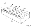
- a corresponding equivalent is shown in FIG. 5.
- This structure then has two barrier layers 3a, 3b, which are produced by Schottky contacts 4a, 4b on the conductive layer (2). Between these two Schottky contacts is an ohmic connection electrode (10), which can be regarded as equivalent to the base connection of a lateral transistor and is provided with the connection (11).
- the two potential peaks which are generated by the barrier layers 3a and 3b are arranged symmetrically with respect to this connection electrode (10).
- connection electrodes (7) or (9) Their distance from the outer connection electrodes (7) or (9) is greater than that from the middle connection electrode (10), so that triangular barriers arise.
- the distance between the potential maximum of the two potential values is preferably less than 0.2 ⁇ m. This small distance between the two potential peaks must be chosen to ensure that electrons that cross the barrier below the Schottky electrode 4a in are able, as hot electrons, to traverse the spatial area in the area of the connection electrode (10) without significant interference, in order then to be able to overcome the potential mountain located below the Schottky electrode 4b if the electrode (9) is appropriately pretensioned.
Landscapes
- Engineering & Computer Science (AREA)
- Microelectronics & Electronic Packaging (AREA)
- Power Engineering (AREA)
- Physics & Mathematics (AREA)
- Ceramic Engineering (AREA)
- Condensed Matter Physics & Semiconductors (AREA)
- General Physics & Mathematics (AREA)
- Computer Hardware Design (AREA)
- Electrodes Of Semiconductors (AREA)
- Bipolar Transistors (AREA)
- Junction Field-Effect Transistors (AREA)
- Semiconductor Integrated Circuits (AREA)
Abstract
Description
Die Erfindung betrifft eine Halbleiteranordnung aus einem Halbleiterkörper (1) und einer darauf angeordneten leitenden Halbleiterschicht (2), an der im Abstand voneinander wenigstens zwei ohmsche Anschlußelektroden (5,6) angeordnet sind.The invention relates to a semiconductor arrangement comprising a semiconductor body (1) and a conductive semiconductor layer (2) arranged thereon, on which at least two ohmic connection electrodes (5, 6) are arranged at a distance from one another.
In neuartigen Majoritätsträger-Bauelementen werden energetische Barrieren für Majoritätsträger dadurch erzeugt, daß in einem einkristallinem Halbleitermaterial eine extrem dünne Schicht kontradotiert eingebettet wird. So wird beispielsweise in ein n-leitfähiges Material mit einer Dotierung von 10¹⁴ Atomen/cm³ eine nur ca. 10 nm dicke Trennschicht extrem hoher p-Dotierung oberhalb 10¹⁹ Atomen/cm³ eingebaut. Wegen der geringen Dicke der kontra-dotierten Schicht verbleiben dort nur Akzeptor-Rümpfe, während die beweglichen Löcher vollständig ausgeräumt sind. Eine derartige PDB-Diode wird beispielsweise in der Zeitschrift "Materials Letters, Vol. 1, No. 1, June 82, S. 22-25" beschrieben. Diese bekannte Diode hat im wesentlichen das Verhalten einer Schottky-Diode, mit dem Vorteil, daß sie relativ rauscharm ist, da die Barriere im Halbleitervolumen und nicht an der Halbleiteroberfläche angeordnet ist.In novel majority carrier components, energy barriers for majority carriers are created by embedding an extremely thin layer in a single crystal in a counter-doped manner. For example, an approx. 10 nm thick separation layer of extremely high p-doping above 10¹ eine atoms / cm³ is built into an n-conductive material with a doping of 10¹⁴ atoms / cm³. Because of the small thickness of the contra-doped layer, only acceptor hulls remain there, while the movable holes are completely cleared out. Such a PDB diode is described, for example, in the journal "Materials Letters, Vol. 1, No. 1, June 82, pp. 22-25". This known diode essentially has the behavior of a Schottky diode, with the advantage that it is relatively low in noise since the barrier is arranged in the semiconductor volume and not on the semiconductor surface.
Ferner ist aus der Zeitschrift "IEE Proc., Vol. 128, Pt.1, No.4, August 81, S.134-140" eine vertikale Transistor-Konfiguration bekannt, bei der heiße Ladungsträger über eine Emissionsbarriere gesteuert in eine dünne Basiszone einfließen, wonach sie über eine daran anschließende zweite Barriere abgesaugt werden. Die Barriere-Schichten werden auch bei diesem Transitor durch extrem schmale, gegenüber dem Umgebungsmaterial kontradotierte Bereiche gebildet, die durch Diffusion oder Ionenimplantation erzeugt werden und die so schmal sind, daß in ihnen nur die Akzeptor-Rümpfe verbleiben. Die beiden Barrierehöhen werden durch Potentialanlegung gegeneinander verändert, so daß bei genügend geringer Ausdehnung der Basisschicht heiße Elektronen die erste Potentialbarriere durchdringen und über die zweite Potentialbarriere abgesaugt werden.Furthermore, a vertical transistor configuration is known from the magazine "IEE Proc., Vol. 128, Pt.1, No.4, August 81, S.134-140", in which hot charge carriers are controlled into an thin base zone via an emission barrier flow in, after which they are suctioned off via a subsequent second barrier. In this transistor too, the barrier layers are formed by extremely narrow regions which are counter-doped to the surrounding material and which are produced by diffusion or ion implantation and which are so narrow that only the acceptor hulls remain in them. The two barrier heights are mutually changed by applying potential, so that when the base layer is sufficiently small, hot electrons penetrate the first potential barrier and are suctioned off via the second potential barrier.
Der Nachteil dieser Konfigurationen ist, daß es sich um eine vertikale Schichtenfolge handelt, was zum Auftreten unerwünschter parasitären Kapazitäten führt. Aufgabe der vorliegenden Erfindung ist es, diesen Nachteil zu beseitigen. Diese Aufgabe wird erfindungsgemäß dadurch gelöst, daß bei einer Halbleiteranordnung der eingangs beschriebenen Art die leitende Schicht derart dünn gewählt ist, daß eine zwischen den ohmschen Anschlußelektroden auf oder in der Halbleiterschicht angeordnete Sperrschicht in der Halbleiterschicht eine als Majoritätsladungsträger-Barriere wirksame Potentialverteilung erzeugt.The disadvantage of these configurations is that it is a vertical layer sequence, which leads to the occurrence of undesirable parasitic capacitances. The object of the present invention is to eliminate this disadvantage. This object is achieved according to the invention in that in a semiconductor arrangement of the type described in the introduction, the conductive layer is chosen to be so thin that a barrier layer arranged between the ohmic connection electrodes on or in the semiconductor layer generates a potential distribution effective as a majority charge carrier barrier in the semiconductor layer.
Die Sperrschicht wird vorzugsweise durch einen Schottky-Kontakt gebildet, der senkrecht zur Längsausdehnung der leitenden Schicht zwischen den ohmschen Anschlußelektroden verläuft. Es besteht jedoch auch die Möglichkeit, die Sperrschicht durch eine gleich angeordnete kontradotierte Zone zu bilden.The barrier layer is preferably formed by a Schottky contact, which runs perpendicular to the longitudinal extent of the conductive layer between the ohmic connection electrodes. However, there is also the possibility of forming the barrier layer by means of an equally arranged contradoped zone.
Bei einer bevorzugten Ausführungsform der Erfindung besteht die leitende Schicht aus einem im Verhältnis zum Material des Halbleiterkörpers schmalbandigem Material, beispielsweise aus GaAs, während der Halbleiterkörper bei diesem Beispiel aus GaAlAs besteht. Die Sperrschicht wird vorzugsweise unsymmetrisch zwischen den ohmschen Anschlußelektroden angeordnet, um eine Dreiecksbarriere, ähnlich der in der Zeitschrift "Materials Letters" beschriebenen Form zu erhalten. Durch die umsymmetrische Anordnung der Sperrschicht zwischen den ohmschen Anschlußelektroden erhält man auch eine ungleiche Kennliniencharakteristik für positive und negative Spannungen, ähnlich der einer Schottky-Diode. Im Gegensatz zu den bekannten vertikalen Anordnungen, liegt der Vorteil der erfindungsgemäßen lateralen Anordnung darin, daß die Elektroden eine geringe gegenseitige Kapazität bilden und das Bauelement mit Hilfe der bekannten planaren Herstellungsmethode erzeugt werden kann.In a preferred embodiment of the invention, the conductive layer consists of a material which is narrow in relation to the material of the semiconductor body, for example GaAs, while the semiconductor body in this example consists of GaAlAs. The barrier layer is preferably arranged asymmetrically between the ohmic connection electrodes in order to obtain a triangular barrier, similar to the shape described in the magazine "Materials Letters". The symmetrical arrangement of the barrier layer between the ohmic connection electrodes also gives an uneven characteristic for positive and negative voltages, similar to that of a Schottky diode. In contrast to the known vertical arrangements, the advantage of the lateral arrangement according to the invention is that the electrodes form a low mutual capacitance and the component can be produced using the known planar production method.
In einer vorteilhaften Weiterbildung wird mit Hilfe des erfindungsgemäßen Prinzips ein Lateral-Transistor dadurch verwirklicht, daß zwei Sperrschichten parallel zueinander zwischen den beiden ohmschen Anschlußelektroden angeordnet werden und zwischen diesen Sperrschichten ein dritter ohmscher Anschlußkontakt an die dünne Halbleiterschicht angebracht wird. Der letztgenannte ohmsche Anschlußkontakt bildet dann ein Äquivalent zu dem ansonsten bei Bipolartransistoren üblichen Basisanschluß. Denkbar ist auch, daß zur Ausbildung steuerbarer Bauelemente mit nur einer Sperrschicht an die mit der Sperrschicht verbundene Elektrode ein variables Potential anlegbar ist und so die Höhe des Potentialberges direkt beeinflußt werden kann.In an advantageous development, a lateral transistor is realized with the aid of the principle according to the invention in that two barrier layers are arranged parallel to one another between the two ohmic connection electrodes and a third ohmic connection contact is attached to the thin semiconductor layer between these barrier layers. The last-mentioned ohmic connection contact then forms an equivalent to the base connection which is otherwise customary in bipolar transistors. It is also conceivable that to form controllable components with only one barrier layer, a variable potential can be applied to the electrode connected to the barrier layer and the height of the potential mountain can thus be influenced directly.
Die Erfindung wird nachstehend noch anhand von Ausführungsbeispielen näher erläutert.
- Fig. 1 zeigt eine Diodenstruktur nach der Erfindung.
- Fig. 2 zeigt die Potentialverteilung in der leitenden Halbleiterschicht.
- Fig. 3 und 4 zeigen den Bänderverlauf entlang der Schnittlinien AAʹ und BBʹ aus
Figur 1. Figur 5 zeigt die Kombination zweier Diodenstrukturen zu einer "hot-electron-Transistorstruktur".
- Fig. 1 shows a diode structure according to the invention.
- 2 shows the potential distribution in the conductive semiconductor layer.
- 3 and 4 show the course of the tape along the section lines AAʹ and BBʹ from Figure 1.
- FIG. 5 shows the combination of two diode structures to form a "hot electron transistor structure".
Gemäß Fig. 1 wird zur Herstellung einer Diodenstruktur mit einem Majoritätsladungsträgerstrom von einem Halbleiterkörper (1) ausgegangen, auf den eine extrem dünne leitende Schicht (2) aufgebracht wird. Die dünne leitende Schicht (2) besteht aus einem gegenüber dem Halbleitergrundkörper (1) schmalbandigem Material, beispielsweise aus GaAs, wenn der Halbleiterkörper (1) aus GaAlAs besteht. Die Halbleiterschicht (2) ist beispielsweise n-dotiert und hat eine Dicke von nur ca. 50 nm. An diese sehr dünne leitende Schicht (2) sind im Abstand voneinander zwei ohmsche Anschlußelektroden (5,6) angebracht, zwischen denen im Betriebsfall der Majoritätsladungsträgerstrom fließt. Dieser Majoritätsladungsträgerstrom hat einen Potentialberg zu überwinden, dessen Verlauf durch die Fig. 2 dargestellt ist. Der Potentialberg wird durch die Sperr-Schicht (3) erzeugt, die unsymmetrisch zwischen den ohmschen Anschlußelektroden (5,6) vorzugsweise streifenförmig augebildet ist. Der Sperrschichtstreifen verläuft hierbei senkrecht zur Stromflußrichtung zwischen den Anschlußelektroden (5,6). Die Sperrschicht wird vorzugsweise durch einen Schottky Kontakt erzeugt; sie kann jedoch auch durch eine einimplantierte kontradotierte Oberflächenzone gebildet werden. Die Sperrschicht hat beispielsweise eine Breite von nur 10-20 nm und wird vorzugsweise durch Elektronenstrahllithographie hergestellt. Nach Fig. 1 entsteht die Sperrschicht (3) durch das Aufbringen eines Metalles (4), das an der Verbindungstelle zur leitenden Schicht (2) einen gleichrichtenden Schottky-Kontakt bildet.According to FIG. 1, a semiconductor body (1) to which an extremely thin conductive layer (2) is applied is used to produce a diode structure with a majority charge carrier current. The thin conductive layer (2) consists of a material with a narrow band compared to the semiconductor base body (1), for example GaAs, if the semiconductor body (1) consists of GaAlAs. The semiconductor layer (2) is, for example, n-doped and has a thickness of only about 50 nm. Two ohmic connection electrodes (5, 6) are attached to this very thin conductive layer (2) at a distance from one another, between which the majority charge carrier current during operation flows. This majority charge carrier current has to overcome a potential mountain, the course of which is shown in FIG. 2. The potential mountain is generated by the barrier layer (3), which is formed asymmetrically between the ohmic connection electrodes (5, 6), preferably in the form of a strip. The barrier layer strip runs perpendicular to the direction of current flow between the connection electrodes (5, 6). The barrier layer is preferably produced by a Schottky contact; however, it can also be formed by an implanted contradoped surface zone. The barrier layer has a width of only 10-20 nm, for example, and is preferably produced by electron beam lithography. 1, the barrier layer (3) is formed by applying a metal (4) which forms a rectifying Schottky contact at the junction with the conductive layer (2).
Der Abstand a zwischen der Sperrschicht (3) und der einen ohmschen Anschlußelektrode (5) und der Abstand b der Sperrschicht gegenüber der anderen ohmschen Anschlußelektrode 6 ist so gewählt, daß entlang der Strecke 0 bis x₁ (Fig. 2) ein unsymmetrischer Potentialberg verläuft. Die Lage der aufgebrachten sperrschichtbildenden Elektrode (4) am Ort x₀ (Fig. 2) bestimmt daher den Verlauf des Potentialberges. Wäre x₀ in der Mitte zwischen 0 und x₁ gelegen, erhielte man einen symmetrischen Potentialberg und auch die Kennlinie zwischen den Elektroden (5,6) hätte einen symmetrischen Verlauf. Ist andererseits wie dargestellt x₀ unsymmetrisch zwischen 0 und x₁ angeordnet, tritt eine ungleiche Charakteristik positiver und negativer Spannungen in ähnlicher Art auf, wie sie bei einer Dreiecksbarriere entsteht, die in der eingangs genannten Zeitschrift "Materials Letters" erwähnt wird. Die Majoritätsladungsträger in der leitenden Schicht (2) müssen mit Hilfe thermischer Energie diesen Potentialberg überwinden, um von einer Anschlußelektrode zur anderen zu gelangen. Der Abstand a beträgt bei einer Ausführungsform beispielsweise 50 nm, während der Abstand b 200 nm groß ist.The distance a between the barrier layer (3) and the one ohmic connection electrode (5) and the distance b of the barrier layer relative to the other
Die zugehörigen Banddiagramme entlang der Schnittlinien AAʹ bzw. BBʹ gemäß Fig. 1 sind in den Fig. 3 und 4 dargestellt. Gemäß diesen Figuren liegt auf der breitbandigen Substratseite schwach dotiertes Material, während an der Oberfläche eine dünne Schicht (2) schmalbandigem Halbleitermaterials angeordnet ist. Die Potentialbarriere zwischen den Bereichen 1 und 2 bewirkt, daß die Ladungsträger -bei einer n-leitenden Schicht (2) die Elektronen- in der Oberflächenschicht (2) verbleiben und in dieser Schicht frei beweglich sind. An der Stelle, wo aufgrund der Sperrschicht (3) eine Potentialbarriere auftritt (Schnitt BBʹ gemäß Fig. 4) wird das Potential der Banddiagramme insgesamt stark angehoben. Dies kann soweit gehen, daß eine Invertierung des Schichtbereiches (2) unterhalb und in engster Nachbarschaft der Metall-Schottky-Elektrode (4) (Fig. 1) auftritt, was bis zum Zustand der Entartung gehen kann.The associated band diagrams along the section lines AAʹ or BBʹ according to FIG. 1 are shown in FIGS. 3 and 4. According to these figures, weakly doped material lies on the broadband substrate side, while a thin layer (2) of narrowband semiconductor material is arranged on the surface. The potential barrier between
Dieser Zustand der Entartung ist bei dem Banddiagramm gemäß Fig. (4) angenommen. Damit besteht der Raumbereich unterhalb der Schottky-Elektrode (4) scheinbar aus hoch p-dotiertem Material und die hier auftretende laterale Barriere entspricht einer Barriere, die bei Camel-Dioden durch extreme Kontradotierung hervorgerufen wird.This state of degeneration is assumed in the band diagram according to FIG. (4). The space below the Schottky electrode (4) thus apparently consists of highly p-doped material and the lateral barrier that occurs here corresponds to a barrier that is caused in Camel diodes by extreme counter-doping.
Gemäß Fig. 1 werden die Anschlußelektroden (5,6) mit Potentialanschlüssen (7,9) versehen. Auch an den Schottky-Kontakt (4) kann eine Anschlußelektrode (8) zur Anlegung eines externen Potentials vorgesehen werden. Mit diesem variablen externen Potential an der Anschlußelektrode (8) könnte die Höhe des Potentialberges gemäß Fig. 2 und damit das elektrische Verhalten der Halbleiteranordnung beeinflußt werden.1, the connection electrodes (5,6) are provided with potential connections (7,9). A connection electrode (8) can also be provided on the Schottky contact (4) for applying an external potential. With this variable external potential at the connection electrode (8), the height of the potential mountain according to FIG. 2 and thus the electrical behavior of the semiconductor arrangement could be influenced.
Durch Kombination von zwei Dioden bzw. Dreieckbarrieren gemäß Fig. 1 läßt sich bei passender Geometrie ein "hot-electron-Transistor" erzeugen. Ein entsprechendes Äquivalent ist in der Fig. 5 dargestellt. Nach der Fig. 5 werden zwei unsymmetrische Anordnungen gemäß der Fig. 1 spiegelbildlich angeordnet. Diese Struktur weist dann zwei Sperrschichten 3a, 3b auf, die durch Schottky-Kontakte 4a, 4b an der leitenden Schicht (2) erzeugt werden. Zwischen diesen beiden Schottky-Kontakten befindet sich im gleichen Anstand eine ohmsche Anschlußelektrode (10), die als Äquivalent zum Basisanschluß eines Lateraltransistors angesehen werden kann und mit dem Anschluß (11) versehen wird. Die beiden Potentialberge, die durch die Sperrschichten 3a und 3b erzeugt werden, sind zu dieser Anschlußelektrode (10) symmetrisch angeordnet. Ihr Abstand zu den äußeren Anschlußelektroden (7) bzw. (9) ist größer als der zur mittleren Anschlußelektrode (10), so daß Dreiecksbarrieren entstehen. Der Abstand zwischen dem Potentialmaximum der beiden Potentialwerte ist vorzugsweise kleiner als 0,2 µm. Dieser geringe Abstand zwischen den beiden Potentialbergen muß gewählt werden, um sicherzustellen, daß Elektronen, die die Barriere unterhalb der Schottky-Elektrode 4a überschreiten, in der Lage sind, als heiße Elektronen das Raumgebiet im Bereich der Anschlußelektrode (10) ohne wesentliche Störung zu durchlaufen, um dann bei passender Vorspannung der Elektrode (9) den unterhalb der Schottky-Elektrode 4b gelegenen Potentialberg überwinden zu können.By combining two diodes or triangular barriers according to FIG. 1, a "hot-electron transistor" can be produced with a suitable geometry. A corresponding equivalent is shown in FIG. 5. 5, two asymmetrical arrangements according to FIG. 1 are arranged in mirror image. This structure then has two barrier layers 3a, 3b, which are produced by Schottky contacts 4a, 4b on the conductive layer (2). Between these two Schottky contacts is an ohmic connection electrode (10), which can be regarded as equivalent to the base connection of a lateral transistor and is provided with the connection (11). The two potential peaks which are generated by the barrier layers 3a and 3b are arranged symmetrically with respect to this connection electrode (10). Their distance from the outer connection electrodes (7) or (9) is greater than that from the middle connection electrode (10), so that triangular barriers arise. The distance between the potential maximum of the two potential values is preferably less than 0.2 μm. This small distance between the two potential peaks must be chosen to ensure that electrons that cross the barrier below the Schottky electrode 4a in are able, as hot electrons, to traverse the spatial area in the area of the connection electrode (10) without significant interference, in order then to be able to overcome the potential mountain located below the Schottky electrode 4b if the electrode (9) is appropriately pretensioned.
Auch bei dem Ausführungsbeispiel nach Fig. 5 besteht die prinzipielle Möglichkeit, die Schottky-Elektroden 4a und 4b zusätzlich zu beschalten, um damit eine Modulation der Potentialberge unterhalb dieser Schottky-Kontakte zu bewirken.In the exemplary embodiment according to FIG. 5, there is also the possibility in principle to additionally connect the Schottky electrodes 4a and 4b in order to thereby modulate the potential peaks below these Schottky contacts.
Claims (14)
Applications Claiming Priority (2)
| Application Number | Priority Date | Filing Date | Title |
|---|---|---|---|
| DE3639433 | 1986-11-18 | ||
| DE19863639433 DE3639433A1 (en) | 1986-11-18 | 1986-11-18 | SEMICONDUCTOR ARRANGEMENT |
Publications (2)
| Publication Number | Publication Date |
|---|---|
| EP0268136A2 true EP0268136A2 (en) | 1988-05-25 |
| EP0268136A3 EP0268136A3 (en) | 1989-03-15 |
Family
ID=6314232
Family Applications (1)
| Application Number | Title | Priority Date | Filing Date |
|---|---|---|---|
| EP87116138A Withdrawn EP0268136A3 (en) | 1986-11-18 | 1987-11-03 | Semiconductor arrangement |
Country Status (4)
| Country | Link |
|---|---|
| US (1) | US4974037A (en) |
| EP (1) | EP0268136A3 (en) |
| JP (1) | JPS63136574A (en) |
| DE (1) | DE3639433A1 (en) |
Cited By (1)
| Publication number | Priority date | Publication date | Assignee | Title |
|---|---|---|---|---|
| EP0366861A1 (en) * | 1988-10-20 | 1990-05-09 | International Business Machines Corporation | Semiconductor ballistic transistor |
Families Citing this family (3)
| Publication number | Priority date | Publication date | Assignee | Title |
|---|---|---|---|---|
| USH1570H (en) * | 1993-03-31 | 1996-08-06 | The United States Of America As Represented By The Secretary Of The Army | Variable lateral quantum confinement transistor |
| US7334901B2 (en) * | 2005-04-22 | 2008-02-26 | Ostendo Technologies, Inc. | Low profile, large screen display using a rear projection array system |
| DE112009005412B4 (en) * | 2009-12-03 | 2021-09-16 | Snaptrack, Inc. | Side emitter and collector transistor and manufacturing process |
Citations (3)
| Publication number | Priority date | Publication date | Assignee | Title |
|---|---|---|---|---|
| US4228444A (en) * | 1976-05-28 | 1980-10-14 | Fujitsu Limited | Semiconductor device |
| JPS584978A (en) * | 1981-07-01 | 1983-01-12 | Mitsubishi Electric Corp | Lateral junction type field-effect transistor |
| EP0100529A1 (en) * | 1982-07-29 | 1984-02-15 | Nec Corporation | High speed field-effect transistor employing heterojunction |
Family Cites Families (7)
| Publication number | Priority date | Publication date | Assignee | Title |
|---|---|---|---|---|
| GB1175601A (en) * | 1966-03-28 | 1969-12-23 | Matsushita Electronics Corp | Insulated-Gate Field-Effect Transistor |
| USRE29971E (en) * | 1971-07-31 | 1979-04-17 | Zaidan Hojin Hondotai Kenkyn Shinkokai | Field effect semiconductor device having an unsaturated triode vacuum tube characteristic |
| FR2465318A1 (en) * | 1979-09-10 | 1981-03-20 | Thomson Csf | FIELD EFFECT TRANSISTOR WITH HIGH BREAKAGE FREQUENCY |
| DE3402517A1 (en) * | 1984-01-26 | 1985-08-01 | Licentia Patent-Verwaltungs-Gmbh, 6000 Frankfurt | Process for fabricating a junction field effect transistor |
| JPS61150372A (en) * | 1984-12-25 | 1986-07-09 | Sony Corp | Semiconductor device |
| JPS61174776A (en) * | 1985-01-30 | 1986-08-06 | Sony Corp | Heterojunction field effect transistor |
| US4632713A (en) * | 1985-07-31 | 1986-12-30 | Texas Instruments Incorporated | Process of making Schottky barrier devices formed by diffusion before contacting |
-
1986
- 1986-11-18 DE DE19863639433 patent/DE3639433A1/en not_active Withdrawn
-
1987
- 1987-10-26 JP JP62268389A patent/JPS63136574A/en active Pending
- 1987-11-03 EP EP87116138A patent/EP0268136A3/en not_active Withdrawn
- 1987-11-09 US US07/117,847 patent/US4974037A/en not_active Expired - Lifetime
Patent Citations (3)
| Publication number | Priority date | Publication date | Assignee | Title |
|---|---|---|---|---|
| US4228444A (en) * | 1976-05-28 | 1980-10-14 | Fujitsu Limited | Semiconductor device |
| JPS584978A (en) * | 1981-07-01 | 1983-01-12 | Mitsubishi Electric Corp | Lateral junction type field-effect transistor |
| EP0100529A1 (en) * | 1982-07-29 | 1984-02-15 | Nec Corporation | High speed field-effect transistor employing heterojunction |
Non-Patent Citations (3)
| Title |
|---|
| 1985 IEEE-MTT-S INTERNATIONAL MICROWAVE SYMPOSIUM DIGEST, St. Louis, 4.-6. Juni 1985, Seiten 423-426, IEEE; J.A. COOPER, Jr.: "Contiguous-domain transferred-electron oscillators" * |
| APPLIED PHYSICS LETTERS, Band 40, Nr. 9, 1. Mai 1982, Seiten 834-836, American Institute of Physics, New York, US; T.J. DRUMMOND et al.: "A novel normally-off camel diode gate GaAs field-effect transistor" * |
| PATENT ABSTRACTS OF JAPAN, Band 7, Nr. 76 (E-167)[1221], 30. März 1983; & JP-A-58 004 978 (MITSUBISHI DENKI K.K.) 12-01-1983 * |
Cited By (2)
| Publication number | Priority date | Publication date | Assignee | Title |
|---|---|---|---|---|
| EP0366861A1 (en) * | 1988-10-20 | 1990-05-09 | International Business Machines Corporation | Semiconductor ballistic transistor |
| US5712491A (en) * | 1988-10-20 | 1998-01-27 | Ibm Corporation | Lateral theta device |
Also Published As
| Publication number | Publication date |
|---|---|
| DE3639433A1 (en) | 1988-05-26 |
| JPS63136574A (en) | 1988-06-08 |
| US4974037A (en) | 1990-11-27 |
| EP0268136A3 (en) | 1989-03-15 |
Similar Documents
| Publication | Publication Date | Title |
|---|---|---|
| DE69224709T2 (en) | Semiconductor device with improved breakdown voltage characteristics | |
| DE69332619T2 (en) | Method of manufacturing a field effect device with an insulated gate | |
| DE2706623C2 (en) | ||
| DE2611338C3 (en) | Field effect transistor with a very short channel length | |
| DE2214935C2 (en) | Integrated MOS circuit | |
| DE69408605T2 (en) | SOI transistor | |
| DE69201436T2 (en) | Quantum well transistor with resonant tunnel effect. | |
| DE2547828B2 (en) | Process for the production of a memory element with a double gate insulated gate field effect transistor | |
| DE69123950T2 (en) | SOI field effect transistor and its manufacturing process | |
| EP0057256A2 (en) | Vertical MIS field effect transistor with low forward resistance | |
| DE2619663B2 (en) | Field effect transistor, method of its operation and use as a high-speed switch and in an integrated circuit | |
| DE102018216855A1 (en) | A silicon carbide semiconductor device and a method of manufacturing a silicon carbide semiconductor device | |
| EP0394757A2 (en) | Method for fabrication of active semiconductor structures using basic structures with surface-parallel 2D-charge carrier layer | |
| DE112018007354T5 (en) | SILICON CARBIDE SEMICONDUCTOR UNIT AND MANUFACTURING METHOD FOR THE SAME | |
| DE102004002723B4 (en) | Semiconductor device with an SOI structure | |
| EP0077481A2 (en) | Planar semiconductor device | |
| DE112006002377T5 (en) | Semiconductor device and method of manufacturing a semiconductor device | |
| EP0585263B1 (en) | Semiconductor detector | |
| EP0095658A2 (en) | Planar semiconductor device and method of making the same | |
| EP1003218A1 (en) | Semiconductor devices comprising a Schottky diode and a diode having a highly doped region and corresponding manufacturing methods | |
| WO2003012854A1 (en) | Semiconductor structure comprising a magnetoresistor | |
| EP0268136A2 (en) | Semiconductor arrangement | |
| DE2818584C2 (en) | Vertical type junction field effect transistor | |
| DE3114971A1 (en) | DMOS semiconductor component | |
| DE3780620T2 (en) | SEMICONDUCTOR STRUCTURE WITH MULTILAYER CONTACT. |
Legal Events
| Date | Code | Title | Description |
|---|---|---|---|
| PUAI | Public reference made under article 153(3) epc to a published international application that has entered the european phase |
Free format text: ORIGINAL CODE: 0009012 |
|
| AK | Designated contracting states |
Kind code of ref document: A2 Designated state(s): DE FR GB IT |
|
| PUAL | Search report despatched |
Free format text: ORIGINAL CODE: 0009013 |
|
| RHK1 | Main classification (correction) |
Ipc: H01L 29/80 |
|
| AK | Designated contracting states |
Kind code of ref document: A3 Designated state(s): DE FR GB IT |
|
| 17P | Request for examination filed |
Effective date: 19890328 |
|
| STAA | Information on the status of an ep patent application or granted ep patent |
Free format text: STATUS: THE APPLICATION IS DEEMED TO BE WITHDRAWN |
|
| 18D | Application deemed to be withdrawn |
Effective date: 19920602 |
|
| RIN1 | Information on inventor provided before grant (corrected) |
Inventor name: BENEKING, HEINZ, PROF. DR. RER. NAT. |