EP0100529A1 - High speed field-effect transistor employing heterojunction - Google Patents
High speed field-effect transistor employing heterojunction Download PDFInfo
- Publication number
- EP0100529A1 EP0100529A1 EP83107446A EP83107446A EP0100529A1 EP 0100529 A1 EP0100529 A1 EP 0100529A1 EP 83107446 A EP83107446 A EP 83107446A EP 83107446 A EP83107446 A EP 83107446A EP 0100529 A1 EP0100529 A1 EP 0100529A1
- Authority
- EP
- European Patent Office
- Prior art keywords
- layer
- semiconductor layer
- effect transistor
- field
- semiconductor
- Prior art date
- Legal status (The legal status is an assumption and is not a legal conclusion. Google has not performed a legal analysis and makes no representation as to the accuracy of the status listed.)
- Granted
Links
- 230000005669 field effect Effects 0.000 title claims description 25
- 239000004065 semiconductor Substances 0.000 claims abstract description 113
- 229910001218 Gallium arsenide Inorganic materials 0.000 claims description 58
- 239000012535 impurity Substances 0.000 claims description 30
- 230000004888 barrier function Effects 0.000 claims description 9
- 229910000530 Gallium indium arsenide Inorganic materials 0.000 claims description 3
- 230000006866 deterioration Effects 0.000 claims description 2
- 230000003647 oxidation Effects 0.000 claims description 2
- 238000007254 oxidation reaction Methods 0.000 claims description 2
- 230000001939 inductive effect Effects 0.000 claims 1
- 238000010586 diagram Methods 0.000 description 14
- 238000005530 etching Methods 0.000 description 12
- 238000004519 manufacturing process Methods 0.000 description 7
- 238000000034 method Methods 0.000 description 7
- 230000004048 modification Effects 0.000 description 6
- 238000012986 modification Methods 0.000 description 6
- 230000008569 process Effects 0.000 description 5
- 239000000758 substrate Substances 0.000 description 5
- 229910045601 alloy Inorganic materials 0.000 description 4
- 239000000956 alloy Substances 0.000 description 4
- 230000008878 coupling Effects 0.000 description 4
- 238000010168 coupling process Methods 0.000 description 4
- 238000005859 coupling reaction Methods 0.000 description 4
- 230000003247 decreasing effect Effects 0.000 description 4
- 238000009792 diffusion process Methods 0.000 description 4
- 229910052737 gold Inorganic materials 0.000 description 4
- 230000002411 adverse Effects 0.000 description 3
- 230000015572 biosynthetic process Effects 0.000 description 3
- 238000000151 deposition Methods 0.000 description 3
- 238000010438 heat treatment Methods 0.000 description 3
- 229910052751 metal Inorganic materials 0.000 description 3
- 239000002184 metal Substances 0.000 description 3
- 229910001092 metal group alloy Inorganic materials 0.000 description 3
- 238000002161 passivation Methods 0.000 description 3
- 229920002120 photoresistant polymer Polymers 0.000 description 3
- IJGRMHOSHXDMSA-UHFFFAOYSA-N Atomic nitrogen Chemical compound N#N IJGRMHOSHXDMSA-UHFFFAOYSA-N 0.000 description 2
- 238000005275 alloying Methods 0.000 description 2
- 230000015556 catabolic process Effects 0.000 description 2
- 150000001875 compounds Chemical class 0.000 description 2
- 238000001451 molecular beam epitaxy Methods 0.000 description 2
- 238000007493 shaping process Methods 0.000 description 2
- 230000009471 action Effects 0.000 description 1
- 238000000137 annealing Methods 0.000 description 1
- 239000007864 aqueous solution Substances 0.000 description 1
- 230000008901 benefit Effects 0.000 description 1
- 230000008859 change Effects 0.000 description 1
- 239000004020 conductor Substances 0.000 description 1
- 230000000694 effects Effects 0.000 description 1
- 230000008020 evaporation Effects 0.000 description 1
- 238000001704 evaporation Methods 0.000 description 1
- 125000005842 heteroatom Chemical group 0.000 description 1
- 239000007788 liquid Substances 0.000 description 1
- 239000000463 material Substances 0.000 description 1
- 150000002739 metals Chemical class 0.000 description 1
- 229910052757 nitrogen Inorganic materials 0.000 description 1
- 238000007747 plating Methods 0.000 description 1
- 238000003860 storage Methods 0.000 description 1
- 229910052725 zinc Inorganic materials 0.000 description 1
Images

Classifications
-
- H—ELECTRICITY
- H01—ELECTRIC ELEMENTS
- H01L—SEMICONDUCTOR DEVICES NOT COVERED BY CLASS H10
- H01L29/00—Semiconductor devices specially adapted for rectifying, amplifying, oscillating or switching and having potential barriers; Capacitors or resistors having potential barriers, e.g. a PN-junction depletion layer or carrier concentration layer; Details of semiconductor bodies or of electrodes thereof ; Multistep manufacturing processes therefor
- H01L29/02—Semiconductor bodies ; Multistep manufacturing processes therefor
- H01L29/06—Semiconductor bodies ; Multistep manufacturing processes therefor characterised by their shape; characterised by the shapes, relative sizes, or dispositions of the semiconductor regions ; characterised by the concentration or distribution of impurities within semiconductor regions
- H01L29/10—Semiconductor bodies ; Multistep manufacturing processes therefor characterised by their shape; characterised by the shapes, relative sizes, or dispositions of the semiconductor regions ; characterised by the concentration or distribution of impurities within semiconductor regions with semiconductor regions connected to an electrode not carrying current to be rectified, amplified or switched and such electrode being part of a semiconductor device which comprises three or more electrodes
- H01L29/1066—Gate region of field-effect devices with PN junction gate
-
- H—ELECTRICITY
- H01—ELECTRIC ELEMENTS
- H01L—SEMICONDUCTOR DEVICES NOT COVERED BY CLASS H10
- H01L29/00—Semiconductor devices specially adapted for rectifying, amplifying, oscillating or switching and having potential barriers; Capacitors or resistors having potential barriers, e.g. a PN-junction depletion layer or carrier concentration layer; Details of semiconductor bodies or of electrodes thereof ; Multistep manufacturing processes therefor
- H01L29/40—Electrodes ; Multistep manufacturing processes therefor
- H01L29/43—Electrodes ; Multistep manufacturing processes therefor characterised by the materials of which they are formed
- H01L29/432—Heterojunction gate for field effect devices
-
- H—ELECTRICITY
- H01—ELECTRIC ELEMENTS
- H01L—SEMICONDUCTOR DEVICES NOT COVERED BY CLASS H10
- H01L29/00—Semiconductor devices specially adapted for rectifying, amplifying, oscillating or switching and having potential barriers; Capacitors or resistors having potential barriers, e.g. a PN-junction depletion layer or carrier concentration layer; Details of semiconductor bodies or of electrodes thereof ; Multistep manufacturing processes therefor
- H01L29/66—Types of semiconductor device ; Multistep manufacturing processes therefor
- H01L29/68—Types of semiconductor device ; Multistep manufacturing processes therefor controllable by only the electric current supplied, or only the electric potential applied, to an electrode which does not carry the current to be rectified, amplified or switched
- H01L29/76—Unipolar devices, e.g. field effect transistors
- H01L29/772—Field effect transistors
- H01L29/778—Field effect transistors with two-dimensional charge carrier gas channel, e.g. HEMT ; with two-dimensional charge-carrier layer formed at a heterojunction interface
- H01L29/7782—Field effect transistors with two-dimensional charge carrier gas channel, e.g. HEMT ; with two-dimensional charge-carrier layer formed at a heterojunction interface with confinement of carriers by at least two heterojunctions, e.g. DHHEMT, quantum well HEMT, DHMODFET
- H01L29/7783—Field effect transistors with two-dimensional charge carrier gas channel, e.g. HEMT ; with two-dimensional charge-carrier layer formed at a heterojunction interface with confinement of carriers by at least two heterojunctions, e.g. DHHEMT, quantum well HEMT, DHMODFET using III-V semiconductor material
-
- H—ELECTRICITY
- H01—ELECTRIC ELEMENTS
- H01L—SEMICONDUCTOR DEVICES NOT COVERED BY CLASS H10
- H01L29/00—Semiconductor devices specially adapted for rectifying, amplifying, oscillating or switching and having potential barriers; Capacitors or resistors having potential barriers, e.g. a PN-junction depletion layer or carrier concentration layer; Details of semiconductor bodies or of electrodes thereof ; Multistep manufacturing processes therefor
- H01L29/66—Types of semiconductor device ; Multistep manufacturing processes therefor
- H01L29/68—Types of semiconductor device ; Multistep manufacturing processes therefor controllable by only the electric current supplied, or only the electric potential applied, to an electrode which does not carry the current to be rectified, amplified or switched
- H01L29/76—Unipolar devices, e.g. field effect transistors
- H01L29/772—Field effect transistors
- H01L29/778—Field effect transistors with two-dimensional charge carrier gas channel, e.g. HEMT ; with two-dimensional charge-carrier layer formed at a heterojunction interface
- H01L29/7786—Field effect transistors with two-dimensional charge carrier gas channel, e.g. HEMT ; with two-dimensional charge-carrier layer formed at a heterojunction interface with direct single heterostructure, i.e. with wide bandgap layer formed on top of active layer, e.g. direct single heterostructure MIS-like HEMT
- H01L29/7787—Field effect transistors with two-dimensional charge carrier gas channel, e.g. HEMT ; with two-dimensional charge-carrier layer formed at a heterojunction interface with direct single heterostructure, i.e. with wide bandgap layer formed on top of active layer, e.g. direct single heterostructure MIS-like HEMT with wide bandgap charge-carrier supplying layer, e.g. direct single heterostructure MODFET
-
- H—ELECTRICITY
- H01—ELECTRIC ELEMENTS
- H01L—SEMICONDUCTOR DEVICES NOT COVERED BY CLASS H10
- H01L29/00—Semiconductor devices specially adapted for rectifying, amplifying, oscillating or switching and having potential barriers; Capacitors or resistors having potential barriers, e.g. a PN-junction depletion layer or carrier concentration layer; Details of semiconductor bodies or of electrodes thereof ; Multistep manufacturing processes therefor
- H01L29/66—Types of semiconductor device ; Multistep manufacturing processes therefor
- H01L29/68—Types of semiconductor device ; Multistep manufacturing processes therefor controllable by only the electric current supplied, or only the electric potential applied, to an electrode which does not carry the current to be rectified, amplified or switched
- H01L29/76—Unipolar devices, e.g. field effect transistors
- H01L29/772—Field effect transistors
- H01L29/80—Field effect transistors with field effect produced by a PN or other rectifying junction gate, i.e. potential-jump barrier
Definitions
- This invention relates to a high speed field-effect transistor ("FET") provided with a heterojunction using compound semiconductors.
- FET field-effect transistor
- a heterojunction of n-GaAlAs and high purity GaAs layers formed by molecular beam epitaxy, a so-called modulation-doped structure, has an extremely high electron mobility at low temperatures such as that of liquid nitrogen. Therefore, the application of such a modulation-doped structure to FETs has been studied. For example, in Applied Physics Letter, Vol.
- an FET which comprises a layer of high-purity (p - -type) GaAs grown on a semi-insulating substrate, a thin n-type undoped GaAlAs layer grown thereon, an Si-doped GaAlAs layer grown on the undoped GaAQAs layer, a gate electrode forming a Schottky junction with the Si-doped GaAlAs layer and source and drain electrodes contacting ohmically with the Si-doped GaA2As layer.
- p - -type high-purity
- the Si-doped and undoped GaAlAs layers under the gate electrode are completely depleted to form a normally-off type FET by a built-in potential of the Schottky barrier formed by the gate electrode. Electron density is increased to form N-type conductive layers at the interface of the GaAs layer and the undoped GaAl2As layer on portions where the gate electrode does not exist. An N-type conductive channel is formed at the interface of the GaAs layer and the undoped GaAlAs layer under the gate electrode by an electrical potential applied to the Schottky gate electrode by capacitive coupling with the depleted GaAlAs layers. Consequently, the transistor is actuated.
- the n-type conductive channel at the interface of the GaAs and undoped GaAlAs layers is very sensitive to the surface state of the Si-doped potential is high, GaMAs layer. If the surface the conductivity of the conductive channel becomes low or infinite. This adverse effect caused by the surface state can be removed by enlarging the thickness of the Si-doped GaAlAs layer except for the portion under the gate electrode or depositing an n +- type GaAs layer on the Si-doped GaAlAs layer except for the gate electrode portion.
- this additional structure adversely affects the planarity at the surface of the upper-most GaAiAs layer, resulting in an increased number of manufacturing steps, a difficulty in shaping the uppermost GaAlAs layer and a difficulty in obtaining a reliable surface passivation.
- An object of this invention is to obtain an FET operable at high speed with a small dynamic or internal resistance and a high voltage applicable to the gate electrode.
- an FET which comprises: a first semi- conductor layer of an intrinsic semiconductor or of a first conductivity type having a low impurity density; a second semiconductor layer of a second conductivity type formed on the first semiconductor layer, the second semiconductor layer being a semiconductor allowing the formation of an inversion region of the second conductivity type at the interface of the first and second semiconductor layers; a third semiconductor layer of the first conductivity type formed on a part of the second semiconductor layer, the third semi- conductor layer having an impurity concentration allowing the formation of a depletion layer over the total thickness of the second semiconductor layer; means for applying a gate potential to the third semiconductor layer; and means positioned on both sides of the third semiconductor layer for applying a source potential and a drain potential to the inversion region at the interface of the first and second semiconductor layers.
- the first conductivity type is p-type and the second conductivity type is n-type.
- the second semiconductor layer is a semiconductor which has a lower electron affinity than the first semiconductor layer.
- the first conductivity type is n-type and the second conductivity type is p-type.
- the second semiconductor layer is a semiconductor which has a larger sum of electron affinity and energy band gap than the first semiconductor layer.
- the impurity concentration of the third semiconductor layer should be selected to a value which extends the depletion layer over the total thickness of the second semi- conductor layer when the third semiconductor is unbiased.
- the impurity concentration of the third semiconductor layer should be selected at a value which extends the depletion of the p-njunction layer/over the total thickness of the second semi- negatively conductor layer when the third semiconductor layer is biased.
- a p-n junction gate is formed by the second semiconductor layer and the third semiconductor layer.
- the thickness of the depletion layer due to the p-n junction is generally larger than the depletion layer due to the Schottky junction and can be widely controlled by adjusting a difference in impurity density between the second semiconductor layer and the third semiconductor layer. That is, for obtaining the same depletion layer as the Schottky junction in the prior art, the impurity density of the second semiconductor layer may therefore be increased to correspondingly increase the carrier density of an inversion layer formed at the interface of the first and second semiconductor layers can be kept high accordingly. Thus an FET with a small dynamic or internal resistance can be obtained.
- the thickness of the second semiconductor layer may be increased. If the thickness of the second semiconductor layer is large, the inversion layer formed at the interface of the first and second semiconductor layer becomes free from the surface state of the second semiconductor layer. Thus a stable and highly conductive inversion layer is obtained at the interface of the first and second semiconductor layers.
- the thickness of the second semiconductor layer under the third semiconductor (gate) layer may be increased by controlling the impurity density of the second and/or third semi- conductor layer.
- the present invention enables the realization of an FET having stable electrical characteristics obtained without affecting the surface planarity, so that the achievement of an easy manufacturing process having a decreased number of manufacturing steps, the easy shaping of the second semiconductor layer, and the easy making of a surface passivation are made possible.
- Another advantage of the invention is that a high voltage may be applied to the gate electrode.
- the barrier height and the reverse breakdown voltage of the p-n junction is exceptionally high compared to those of the Schottky junction. Therefore, the FET of this invention operates as a normal transistor even when an input signal with a large voltage is applied thereto.
- an FET with a conventional modulation-doped structure includes a high-purity GaAs layer 12 free from impurities and formed on a GaAs substrate 11 semi-insulated by Cr doped therein.
- An n-type GaAlAs layer 13 in which an impurity of si or the like is doped is provided on the layer 12.
- Source and drain electrodes 15 and 16 are formed by depositing a metal on the .layer 13 and diffusing the metal into the GaAkAs layer 13 to reach the layer 12.
- a gate electrode 14 isolated from but located between the source and drain electrodes 15 and 16 is formed to make a Schottky junction with the layer 13.
- the energy band diagram at a portion between the gate electrode 14 and the source or drain electrode 15 or 16 (B - B' in Fig. 1) is shown in Fig. 3.
- E F denotes the Fermi level
- E c the level of the lower edge of the conduction band
- E v the level of the upper edge of the valence band.
- the surface potential of the n-type GaAlAs layer 13 is so small that the surface depletion layer due to the surface potential is thinner than the total thickness of the layer 13, and consequently, the. surface depletion layer never reaches the high-purity GaAs layer 12.
- a quantity of electrons corresponding to the charge due to an ionized donor impurities in the layer 13 form electron layers 17 at the interface of"the GaAlAs layer 13 and the GaAs layer 12.
- the electron layers 17 are connected in ohmic contact to the source and drain regions.
- the energy band diagram at a portion under the gate electrode (A - A' in Fig. 1) is shown in Fig. 2 as a case of a normally-off type FET.
- the thickness and impurity density of the n-type GaAlAs layer 13 are established so that layer 13 is depleted over the total thickness thereof by the built-in potential of the Schottky barrier due to the contact with the gate electrode 14. Therefore, no electron layer is formed at the interface of the layers 12 and 13 under the electrode 14. Consequently, in the absence of any potential applied to the gate electrode 14, no conductive channel is formed between the source and drain electrodes 15 and 16, with the result that no current flows.
- the semi- conductor device shown in Fig. 1 operates as an FET which amplifies an input signal applied to the gate electrode 14.
- the layers 17 must be kept at a sufficiently low specific resistance. This may be achieved by sufficiently increasing the impurity density of the n-type GaAlAs layer 13 to cause the gate electrode to be brought into ohmic contact with the layer 13.
- Another method for keeping the layers 17 at a sufficiently low specific resistance without adjusting the impurity density of the layer 13, is to keep the surface potential of the layer 13 sufficiently small.
- the surface control of Group III - V compound semiconductors is not an easy task. If the surface potential of the GaAlAs layer 13 is high, the surface depletion layer extends to decrease the number of carrier in the electron layers 17, resulting in an increase in a specific resistance of the layers 17. In particular, when the surface potential increases to a value the same as the surface potential under the gate electrode 14, the electron layers 17 disappear.
- Fig. 4 shows one of these proposals wherein an n-type GaA2As layer 13' is formed thick except at the portion under the gate electrode 14. The depletion layer extended by the surface potential stays removed from the GaAs layer 12 in the thick GaAlAs layer 13'. Accordingly, the influence of the surface potential to the electron layers 17 is minimized.
- Fig. 5 shows another proposal wherein an n +- type GaAs layer 18 having a high impurity density is provided over the n-type GaAlAs layer 13 except where the gate electrode 14 exists.
- the depletion layer due to the surface potential of the GaAs layer 18 is maintained away from the GaAs layer 12 to minimize the influence of the surface potential to the electron layers 17.
- the structures of Figs. 4 and 5 adversely affect the flatness of the GaAlAs layer 13, which makes it difficult to manufacture the FET. This is attributed to an increased number of manufacturing steps, difficult formation of the GaAlAs layer 13' and the GaAs layer 18, and unreliable passivation of the device surface due to fine unevenness. It is also difficult to form the FET in a monolithic integrated circuit.
- Another disadvantage of the conventional FET is that, as will be apparent from Fig. 2, the height of the barrier between the gate electrode 14 and the electrons to be produced at the interface of the GaAs layer 12 and the GaAlAs layer 13 under the gate electrode 14 is nearly the same as the usual metal- semiconductor junction and is only 0.8 eV. Accord- ingly, a large positive voltage cannot be applied to the gate electrode 14. In other words, the possible input signals are limited to small voltages.
- a first embodiment of the invention comprises a p - -type GaAs layer 22 with an effective acceptor density of approximately 1 x 10 14 cm -3 , which is formed to have a thickness of several microns over a semi-insulating GaAs substrate 21 with Cr doped therein.
- a lower acceptor density would be preferable for making the p - -type GaAs layer 22.
- An acceptor density of about 1 x 10 14 cm -3 does not affect the device operation, but it should be less than 1 x 10 16 cm , to main-As tain high mobility.
- An n-type Ga 0.7 Al 0.3 /layer 23 with an effective density of 5x10 17 cm -3 and a thickness of about 600 A is provided on the GaAs layer 22.
- the donor density of the GaAlAs layer 23 is preferably selected in a range of 1 x 10 17 cm -3 and .
- a p-type Ga 0.7 Al 0.3 / layer 24 to have an effective acceptor density of 1 x 10 19 cm - 3 , 0 a thickness of about 100 A and a width of about 0.5 ⁇ m is provided on the GaAlAs layer 23 at its center to form a p-n junction therewith.
- a metallic gate electrode 25 of Al is formed in ohmic contact with the p + -type GaAlAs layer 24.
- the impurity density of the layer 24 should be higher than that of the GaAlAs layer 23 and selected to be a value high enough to allow the depletion layer to extend in the n-type GaAlAs layer 23 to reach the p - -type GaAs layer 22 when unbiased.
- Source and drain electrodes 26 and 27 are formed in the following steps.
- An alloy of Au and Ge is evaporated on the GaAlAs layer 23 at the portion where the electrodes 26 and 27 are formed, followed by the evaporation of Ni onto the alloy of Au and Ge. Thereafter, by alloying the Ni and the alloy of Au and Ge with the GaAlAs layer 23 and the GaAs layer 22 in an annealing procedure, the metallic alloy thereof is grown downwardly to reach the interface of the layers 22 and 23.
- the formed metallic alloy is used as the source electrode 26 and the drain electrode 27. Therefore, the metallic alloy must have a property to ohmic contact with carrier (electron in this case) layers 28 at the interface of the layers 22 and 23.
- a semi-insulative InP may be used for the semi-insulative GaAs 21.
- a high-purity InGaAs may be substituted for the high-purity GaAs layer 22, n-type InP or n-type AlInAs for the n-type GaAlAs 23 and p +- type InP or P + -type AlInAs for the P +- type GaAlAs 24.
- the conductivity type of all the semiconductor layers 22, 23, and 24 may be reversed to obtain a p-channel type FET.
- the upper limit of the density should be 1 x 10 16 cm -3 to maintain a high mobility.
- Figs. 7 (a) and 7 (b) are energy band diagrams in thermal-equilibrium, wherein Fig. 7 (a) is a section view taken along the line C - C 1 (gate region) of Fig. 6 and Fig. 7 (b) is taken along the line D - D' (between gate and source regions) of Fig. 6.
- Fig. 8 is an energy band diagram taken along the line C - C 1 of Fig. 6 when an n-channel 29 is formed at the interface of the GaAs layer 22 and the GaAlAs layer 23 under the GaA2As layer 24 by applying a positive voltage to the gate electrode 25.
- E F ' denotes the quisi-Fermi level. Namely, in the thermal equilibrium, the layer 23 under the layer 24 is completely depleted only by the diffusion potential difference of the p-n junction with the layer 24. Accordingly, electrons are not stored at the interface of the n-type GaAlAs layer 23 and the p - -type GaAs layer 22, with the result that no electron layer is formed. This mode is illustrated in Fig. 7 (a). On the other hand, electron layers 28 are formed at the interface of the layers 23 and 22 except for the portion under the p-type GaMAs layer 24, as shown in Fig. 7 (b).
- the electron layers 28 are in ohmic contact with the source and drain electrodes 26 and 27 and operate essentially as a source region and a drain region.
- a positive voltage to the gate electrode 25 electrons are produced at the hetero interface of the n-type GaAlAs layer 23 and the p - -type GaAs layer 22 in the gate region by capacitive coupling with the depleted layer 23 so as to form an electron layer 29 shown in Fig. 8..A current flows between the source and drain electrodes 26 and 27 through the layer 29 and the electron layers 28, thus producing the transistor operation.
- the FET of Fig. 6 may have a thick n-type GaAQAs layer 23 and/or a high donor density of the layer 23.
- the impurity doping level of the p +- type GaAlAs layer 24 should be made larger than the impurity doping level of the layer 23.
- the electron storage in the electron layers 28 at the interface of the p - -type GaAs layer 22 and the n-type GaAlAs layer 23 can be made larger by increasing the thickness and/or the impurity doping level of the layer 23 to minimize the internal resistance of the FET.
- the p +- type GaAlAs layer 24 is somewhat thicker than the depletion layer due to junction between the layers 23 and 24 extending to the layer 24.
- any extension of the depletion layer is limited.
- the p +- type GaAlAs layer 24 can be made thin, so that the unevenness of the surface can be suppressed to a degree almost similar to that of a planer planer FET.
- a p -type GaAs layer which is 1 x 10 14 cm -3 in effective acceptor density is used for the GaAs layer 12, and an n-type As Ga 0.7 Al 0.3 /layer with an effective donor density of 5 x 10 17 cm -3 is used for the n-type GaAlAs layer 13.
- the barrier height of the Schottky gate is given at 0.8 eV, and the surface potential of the layer 13 other than the portion under the gate electrode is 0.4V, given at the same as the surface potential of the n-type GaAlAs layer 23 of this invention. Further, it is assumed that the interfaces between each of the semiconductor layers 11, 12 and 13 are formed abruptly to perfection.
- the thickness of the n-type GaAlAs layer 13 0 in the normally-off FET is about 350 A, the surface GaAlAs 13 0.4V, potential of the layer is and the sheet density of electrons in the electron layers 17 at the interface of the layers 12 and 13 is about 7 x 10 11 cm -2 .
- the same as the the normally-off FET having-a- threshold voltage conventional examples can have the thickness of the n-type GaAlAs layer 23 increased to about 600 A, and hence the surface density of electrons in the electron layers 28 at the interface of the GaAs layer 22 and the GaAlAs layer. 23 may grow very high to about 1 . 4 x 10 12 cm -2 when compared with the conventional examples.
- the thickness of the n-type GaAlAs layer 23 can be maintained at about 400 A even after increasing the effective donor density of the n-type GaAlAs layer 23 to 1 x 10 18 cm -3 In this case, the surface density of electrons in the electron layers 28 at the interface of the GaAs layer 22 and the GaAlAs layer 23 becomes about 2 x 10 12 cm -2 , and the internal resistance of the transistor can be further decreased. Furthermore, in the conventional examples, if the surface potential of the n-type GaAlAs layer 13 increases and thus becomes the same as that of the part under the gate electrode 14, the electron layers 17 will not be formed, therefore source and drain resistances become infinite.
- the internal resistance of the transistor is not influenced much by the surface potential of the n-type GaA2As layer 23.
- the height of the barrier of the gate electrode against electrons in the channel to be formed between the electron layers 28 is about 1.8 eV, which is so very high it is at least twice that of a conventional Schottky gate. Therefore, the range of input signal voltage to be applied is much higher than that for the conventional examples.
- Figs. 9 (a) to 9 (d) The high-purity GaAs layer 22, n-type GaAlAs layer 23 and p +- type GaA£As layer 24 are grown consecutively onto the semi-insulating GaAs substrate 21 by, for example, molecular beam epitaxy (Fig. 9 (a)).
- An Al film for example, is disposed over the whole surface of the p +- type GaA2As layer 24, and then etched selectively to form the gate electrode 25 (Fig. 9 (b)).
- the gate electrode 25 is formed by covering the unwanted parts of the p + -type GaAlAs layer 24 with a film of photoresist, depositing Al film over the entire surface, and then removing the Al film on the photoresist together with the photoresist.
- the source electrode 26 and the drain electrode 27 are formed by, for example, plating an alloy of Au and Ge and a film of Ni consecutively on the GaAlAs layer 24 and alloying the metals with the semiconductors of the layers 24, 23 and 22 (Fig. 9 (c)).
- the p +- type GaAeAs layer 24 between the gate electrode 25 and the source electrode 26, and between the gate electrode 25 and the drain electrode 27 is removed by etching (Fig. 9 (d)). The process shown in Fig.
- the source and drain electrodes 26 and 27 is not necessarily limited to where they are formed after the gate electrode 25 is formed; they can be formed at any time after all the semiconductor layers 22, 23 and 24 have been grown.
- the gate electrode 25 can be used as a mask for etching.
- the etching of the GaAlAs layer 24 can also be done while measuring the current/voltage characteristics of two or three of the gate, source and drain electrodes 25, 26 and 27.
- the timing for stopping etching for minimizing the source resistance can easily be determined by measuring the current/voltage characteristics at the same time of etching.
- the semiconductor device of the invention is capable of controlling its threshold voltages by the diffusion of an acceptor impurity from the p + -type GaAlAs layer 24 by heat treatment into the n-type GaAlAs layer 23.
- acceptor impurities can be 0 diffused at temperature 600 C, for example, much lower than that at which the donor impurities (Si, for example) of the n-type GaAlAs layer 23 diffuse, therefore the position of the p-n junction between the p +- type GaAlAs layer 24 and the n-type GaAlAs layer 23 can be shifted to the layer 23 side without affecting heterojunction the of the layer 23 and the high-purity GaAs layer 22.
- the threshold voltage can accordingly be shifted to the positive side.
- the above heat treatment can be done at any time during the process shown in Fig. 9 (a) to Fig. 9 (d).
- the sectional structure of the transistor is shown in Fig. 9 (e).
- the heat treatment carried out after the process of Fig. 9 (d) allows the diffusion to be caused while measuring the characteristics, which is convenient for controlling the threshold voltage.
- a p +- type GaAs layer 34 can be -employed, as shown in Fig. 10, instead of the p -type GaAlAs layer 24.
- an etchant which does not etch the n-type GaAlAs layer 23 or which has an extremely small etching rate for n-type GaAlAs can be selected as the etchant for selectively etching the p +- type GaAs layer (34).
- an FET with a short effective gate length can be obtained by etching the p +- type GaAs layer 34 to a given shape with the gate electrode 25 acting as an etching mask, and then further side-etching the layer 34.
- Alkaline KI 3 , KI and KOH aqueous solutions can be used as the etchant in this case.
- the thermal equilibrium energy band diagram of the gate electrode portion at the section E - E' of Fig. 10 is shown in Fig. ll.
- the height of the gate barrier is somewhat the decreased as compared with the case wherein As p+- type Ga 0.7 Al 0.3 / layer 24 is used.
- the surface density of electrons in the electron layers at the interface of the p - -type GaAs layer 22 and the n-type GaAlAs layer 23 remains almost unchanged.
- N + regions 30 and 31 are formed near the source and drain electrodes 26 and 27 so that electrons are smoothly supplied and efficiently collected to and from the electron layers 28 at the interface of p - -type GaAs layer 22 and the n-type GaAlAs layer 23.
- the electrons are supplied from the N + regions 30 and 31, not only can the internal resistance of the field-effect transistor be decreased, but also the ohmic contacts of the source and drain electrodes 26 and 27 can be improved.
- a third embodiment of the invention has an n +- type GaAs layer 32 provided over the n-type GaAlAs layer 23 and the p +- type GaAs layer 24 provided over the layer 32. Oxidation and deterioration with time of the n-type GaAlAs layer 23 can be prevented by the n + -type GaAs layer 32. Further, the surface potential of the n-type GaAlAs layer 23 can be maintained low by the n -type GaAs layer 32, thus increasing the sheet density of electrons in the electron layers 28. It is not necessary for the layer 32 to form a definite layer. The layer 32 may be in any state that will allow the n-type GaAfAs layer 23 to change from GaAlAs to GaAs gradually toward the surface.
- the device is fundamentally the same in structure as that of Fig. 6 except that high-purity GaAlAs in which no impurity is doped is applied over the portion wherein the n-type GaAlAs layer 23 abuts the p - -type GaAs layer 22.
- the electron mobility at the interface between the p - -type GaAs layer 22 and the GaAlAs layer 23 can be further increased.
- a p-channel FET can be obtained.
- the fundamental structure is the same as that of Fig. 6.
- the energy band structure will be described with reference to Fig. 14 showing the energy band diagram in the region of the gate electrode.
- a first semi- conductor layer 22' of high-purity or n-type low-impurity density is provided on a high-resistance substrate.
- a second semiconductor layer 23' which is p-type with a larger sum of electron affinity and band gap than that of the first semiconductor layer 22' is provided over the first layer 22'.
- a gate electrode 25' is provided on the p-type layer 23' over an n-type layer 24'.
- the source and drain electrodes are disposed on either side of the gate electrode 25'.
- the thermal equilibrium energy band diagram of the gate region is shown in Fig. 14. As is apparent from Fig. 14, the p-type layer 23' is completely depleted in the gate region, and the transistor action is effected by capacitive coupling with the depleted semiconductor layer. Ge can be used for the first semiconductor layer 22' and GaAs can be used for the layer 23' and the layer 24'.
Landscapes
- Engineering & Computer Science (AREA)
- Microelectronics & Electronic Packaging (AREA)
- Power Engineering (AREA)
- Physics & Mathematics (AREA)
- Ceramic Engineering (AREA)
- Condensed Matter Physics & Semiconductors (AREA)
- General Physics & Mathematics (AREA)
- Computer Hardware Design (AREA)
- Chemical & Material Sciences (AREA)
- Materials Engineering (AREA)
- Junction Field-Effect Transistors (AREA)
Abstract
Description
- This invention relates to a high speed field-effect transistor ("FET") provided with a heterojunction using compound semiconductors.
- A heterojunction of n-GaAℓAs and high purity GaAs layers formed by molecular beam epitaxy, a so-called modulation-doped structure, has an extremely high electron mobility at low temperatures such as that of liquid nitrogen. Therefore, the application of such a modulation-doped structure to FETs has been studied. For example, in Applied Physics Letter, Vol. 40, No.6, Pages 530-532, an FET is proposed which comprises a layer of high-purity (p--type) GaAs grown on a semi-insulating substrate, a thin n-type undoped GaAℓAs layer grown thereon, an Si-doped GaAℓAs layer grown on the undoped GaAQAs layer, a gate electrode forming a Schottky junction with the Si-doped GaAℓAs layer and source and drain electrodes contacting ohmically with the Si-doped GaA2As layer. The Si-doped and undoped GaAℓAs layers under the gate electrode are completely depleted to form a normally-off type FET by a built-in potential of the Schottky barrier formed by the gate electrode. Electron density is increased to form N-type conductive layers at the interface of the GaAs layer and the undoped GaAℓ2As layer on portions where the gate electrode does not exist. An N-type conductive channel is formed at the interface of the GaAs layer and the undoped GaAℓAs layer under the gate electrode by an electrical potential applied to the Schottky gate electrode by capacitive coupling with the depleted GaAℓAs layers. Consequently, the transistor is actuated.
- High speed operation can be obtained in such a transistor having a Hall mobility of 38,000 cm2V-1sec-1 at 77°K. However, this transistor exhibits drawbacks based on the Schottky junction type gate electrode. That is, to form a Schottky Si-doped junction, the GaAℓAs layer must have low impurity denisty and reduced thickness. If not present, the depletion layer formed by the Schottky junction will be broken or it expands to an unfavorable extent. This results in a considerably high dynamic or internal resistance of the transistor. Further, becuase the breakdown voltage of the Schottky junction is essentially low, the voltage applicable to the gate is limited to a low voltage.
- Furthermore, the n-type conductive channel at the interface of the GaAs and undoped GaAℓAs layers is very sensitive to the surface state of the Si-doped potential is high, GaMAs layer. If the surface the conductivity of the conductive channel becomes low or infinite. This adverse effect caused by the surface state can be removed by enlarging the thickness of the Si-doped GaAℓAs layer except for the portion under the gate electrode or depositing an n+-type GaAs layer on the Si-doped GaAℓAs layer except for the gate electrode portion. However, this additional structure adversely affects the planarity at the surface of the upper-most GaAiAs layer, resulting in an increased number of manufacturing steps, a difficulty in shaping the uppermost GaAℓAs layer and a difficulty in obtaining a reliable surface passivation.
- An object of this invention is to obtain an FET operable at high speed with a small dynamic or internal resistance and a high voltage applicable to the gate electrode.
- According to one aspect of this invention, there is provided an FET which comprises: a first semi- conductor layer of an intrinsic semiconductor or of a first conductivity type having a low impurity density; a second semiconductor layer of a second conductivity type formed on the first semiconductor layer, the second semiconductor layer being a semiconductor allowing the formation of an inversion region of the second conductivity type at the interface of the first and second semiconductor layers; a third semiconductor layer of the first conductivity type formed on a part of the second semiconductor layer, the third semi- conductor layer having an impurity concentration allowing the formation of a depletion layer over the total thickness of the second semiconductor layer; means for applying a gate potential to the third semiconductor layer; and means positioned on both sides of the third semiconductor layer for applying a source potential and a drain potential to the inversion region at the interface of the first and second semiconductor layers.
- For an n-channel FET the first conductivity type is p-type and the second conductivity type is n-type. The second semiconductor layer is a semiconductor which has a lower electron affinity than the first semiconductor layer. To the contrary, for the p-channel FET, the first conductivity type is n-type and the second conductivity type is p-type. The second semiconductor layer is a semiconductor which has a larger sum of electron affinity and energy band gap than the first semiconductor layer. Further, in the case of a normally-off type FET, the impurity concentration of the third semiconductor layer should be selected to a value which extends the depletion layer over the total thickness of the second semi- conductor layer when the third semiconductor is unbiased. For the normally-on type FET, the impurity concentration of the third semiconductor layer should be selected at a value which extends the depletion of the p-njunction layer/over the total thickness of the second semi- negatively conductor layer when the third semiconductor layer is biased.
- According to this invention, a p-n junction gate is formed by the second semiconductor layer and the third semiconductor layer. The thickness of the depletion layer due to the p-n junction is generally larger than the depletion layer due to the Schottky junction and can be widely controlled by adjusting a difference in impurity density between the second semiconductor layer and the third semiconductor layer. That is, for obtaining the same depletion layer as the Schottky junction in the prior art, the impurity density of the second semiconductor layer may therefore be increased to correspondingly increase the carrier density of an inversion layer formed at the interface of the first and second semiconductor layers can be kept high accordingly. Thus an FET with a small dynamic or internal resistance can be obtained.
- Furthermore, because the thickness of the depletion layer due to the p-n junction is essentially larger than the depletion layer due to the Schottky junction, the thickness of the second semiconductor layer may be increased. If the thickness of the second semiconductor layer is large, the inversion layer formed at the interface of the first and second semiconductor layer becomes free from the surface state of the second semiconductor layer. Thus a stable and highly conductive inversion layer is obtained at the interface of the first and second semiconductor layers. The thickness of the second semiconductor layer under the third semiconductor (gate) layer may be increased by controlling the impurity density of the second and/or third semi- conductor layer. Therefore, the present invention enables the realization of an FET having stable electrical characteristics obtained without affecting the surface planarity, so that the achievement of an easy manufacturing process having a decreased number of manufacturing steps, the easy shaping of the second semiconductor layer, and the easy making of a surface passivation are made possible.
- Another advantage of the invention is that a high voltage may be applied to the gate electrode. The barrier height and the reverse breakdown voltage of the p-n junction is exceptionally high compared to those of the Schottky junction. Therefore, the FET of this invention operates as a normal transistor even when an input signal with a large voltage is applied thereto.
- The above and other features and objects of the invention will become more apparent from the following detailed description taken in conjunction with the accompanying drawings, wherein:
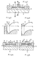
- Fig. 1 is a cross-sectional view of one example of a conventional FET;
- Fig. 2 is an energy band diagram in a thermal equilibrium, taken along the line A - A' of Fig. 1;
- Fig. 3 is an energy band diagram in a thermal equilibrium, taken along the line B - B' of Fig. 1;
- Fig. 4 is a cross-sectronal view of another example of a conventional FET;
- Fig. 5 is a cross-sectional view of a still other example of a conventional FET;
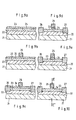
- Fig. 6 is a cross-sectional view of a first embodiment of the present invention;
- Fig. 7 (a) is an energy band diagram in a thermal equilibrium, taken along the line C - C' of Fig. 6;
- Fig. 7 (b)-is an energy band diagram in a thermal equilibrium, taken along the line D - D' of Fig. 6;
- Fig. 8 is an energy band diagram when a positive voltage is applied to the gate electrode of the first embodiment, taken along line C - C' of Fig. 6;
- Fig. 9 (a) to Fig. 9 (e) are cross-sectional views of each stage of the process of manufacturing the first embodiment of the invention;
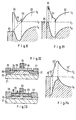
- Fig. 10 is a cross-sectional view of a modification of the first embodiment of the invention;
- Fig. 11 is an energy band diagram in a thermal equilibrium, taken along the line E - E' of Fig. 10;
- Fig. 12 is a cross-sectional view of a second embodiment of the invention;
- Fig. 13 is a cross-sectional view of a third embodiment of the invention; and
- Fig. 14 is an energy band diagram in a thermal equilibrium at the section of the gate region of a fifth embodiment of the invention.
- Referring to Fig. 1, an FET with a conventional modulation-doped structure includes a high-
purity GaAs layer 12 free from impurities and formed on aGaAs substrate 11 semi-insulated by Cr doped therein. An n-type GaAℓAs layer 13 in which an impurity of si or the like is doped is provided on thelayer 12. Source anddrain electrodes layer 13 and diffusing the metal into theGaAkAs layer 13 to reach thelayer 12. Agate electrode 14 isolated from but located between the source anddrain electrodes layer 13. - In a state of thermal equilibrium, the energy band diagram at a portion between the
gate electrode 14 and the source ordrain electrode 15 or 16 (B - B' in Fig. 1) is shown in Fig. 3. In Figs. 2 and 3, EF denotes the Fermi level, Ec the level of the lower edge of the conduction band, and Ev the level of the upper edge of the valence band. The surface potential of the n-type GaAℓAs layer 13 is so small that the surface depletion layer due to the surface potential is thinner than the total thickness of thelayer 13, and consequently, the. surface depletion layer never reaches the high-purity GaAs layer 12. A quantity of electrons corresponding to the charge due to an ionized donor impurities in thelayer 13 form electron layers 17 at the interface of"theGaAℓAs layer 13 and theGaAs layer 12. The electron layers 17 are connected in ohmic contact to the source and drain regions. - On the other hand, the energy band diagram at a portion under the gate electrode (A - A' in Fig. 1) is shown in Fig. 2 as a case of a normally-off type FET. The thickness and impurity density of the n-
type GaAℓAs layer 13 are established so thatlayer 13 is depleted over the total thickness thereof by the built-in potential of the Schottky barrier due to the contact with thegate electrode 14. Therefore, no electron layer is formed at the interface of thelayers electrode 14. Consequently, in the absence of any potential applied to thegate electrode 14, no conductive channel is formed between the source and drainelectrodes electrode 14, electrons are generated at the interface of theGaAs layer 12 and theGaAAAs layer 13 by capacitive coupling with thelayer 13 to form an n-type conductive channel between the electron layers 17. Thus, current flows between the source and drainelectrodes gate electrode 14. - For the semiconductor device of Fig. 1, to operate as an FET with a small internal resistance, the
layers 17 must be kept at a sufficiently low specific resistance. This may be achieved by sufficiently increasing the impurity density of the n-type GaAℓAs layer 13 to cause the gate electrode to be brought into ohmic contact with thelayer 13. Another method for keeping thelayers 17 at a sufficiently low specific resistance without adjusting the impurity density of thelayer 13, is to keep the surface potential of thelayer 13 sufficiently small. However, the surface control of Group III - V compound semiconductors is not an easy task. If the surface potential of theGaAℓAs layer 13 is high, the surface depletion layer extends to decrease the number of carrier in the electron layers 17, resulting in an increase in a specific resistance of thelayers 17. In particular, when the surface potential increases to a value the same as the surface potential under thegate electrode 14, the electron layers 17 disappear. - Conceivable structures for eliminating these influences exerted by the surface potential have been proposed. Fig. 4 shows one of these proposals wherein an n-type GaA2As layer 13' is formed thick except at the portion under the
gate electrode 14. The depletion layer extended by the surface potential stays removed from theGaAs layer 12 in the thick GaAℓAs layer 13'. Accordingly, the influence of the surface potential to the electron layers 17 is minimized. Fig. 5 shows another proposal wherein an n+-type GaAs layer 18 having a high impurity density is provided over the n-type GaAℓAs layer 13 except where thegate electrode 14 exists. Similar to the thick GaA2As layer 13', the depletion layer due to the surface potential of theGaAs layer 18 is maintained away from theGaAs layer 12 to minimize the influence of the surface potential to the electron layers 17. However, the structures of Figs. 4 and 5 adversely affect the flatness of theGaAℓAs layer 13, which makes it difficult to manufacture the FET. This is attributed to an increased number of manufacturing steps, difficult formation of the GaAℓAs layer 13' and theGaAs layer 18, and unreliable passivation of the device surface due to fine unevenness. It is also difficult to form the FET in a monolithic integrated circuit. - Another disadvantage of the conventional FET is that, as will be apparent from Fig. 2, the height of the barrier between the
gate electrode 14 and the electrons to be produced at the interface of theGaAs layer 12 and theGaAℓAs layer 13 under thegate electrode 14 is nearly the same as the usual metal- semiconductor junction and is only 0.8 eV. Accord- ingly, a large positive voltage cannot be applied to thegate electrode 14. In other words, the possible input signals are limited to small voltages. - Referring now to Fig. 6, a first embodiment of the invention comprises a p--
type GaAs layer 22 with an effective acceptor density of approximately 1 x 1014 cm-3, which is formed to have a thickness of several microns over asemi-insulating GaAs substrate 21 with Cr doped therein. A lower acceptor density would be preferable for making the p--type GaAs layer 22. An acceptor density of about 1 x 1014 cm-3 does not affect the device operation, but it should be less than 1 x 1016 cm , to main-As tain high mobility. An n-type Ga0.7Aℓ0.3/layer 23 with an effective density of 5x1017 cm-3and a thickness of about 600 A is provided on theGaAs layer 22. The donor density of theGaAℓAs layer 23 is preferably selected in a range of 1 x 1017 cm-3 and . As for 1 x 1019 cm-3. A p-type Ga0.7Aℓ0.3/layer 24 to have an effective acceptor density of 1 x 1019 cm-3, 0 a thickness of about 100 A and a width of about 0.5 µm is provided on theGaAℓAs layer 23 at its center to form a p-n junction therewith. Ametallic gate electrode 25 of Aℓ, for example, is formed in ohmic contact with the p+-type GaAℓAs layer 24. The impurity density of thelayer 24 should be higher than that of theGaAℓAs layer 23 and selected to be a value high enough to allow the depletion layer to extend in the n-type GaAℓAs layer 23 to reach the p--type GaAs layer 22 when unbiased. Source anddrain electrodes - An alloy of Au and Ge is evaporated on the
GaAℓAs layer 23 at the portion where theelectrodes GaAℓAs layer 23 and theGaAs layer 22 in an annealing procedure, the metallic alloy thereof is grown downwardly to reach the interface of thelayers source electrode 26 and thedrain electrode 27. Therefore, the metallic alloy must have a property to ohmic contact with carrier (electron in this case) layers 28 at the interface of thelayers - As alternative materials, a semi-insulative InP may be used for the
semi-insulative GaAs 21. Similarly, a high-purity InGaAs may be substituted for the high-purity GaAs layer 22, n-type InP or n-type AℓInAs for the n-type GaAℓAs 23 and p+-type InP or P+-type AℓInAs for the P+-type GaAℓAs 24. It will be appreciated that the conductivity type of all the semiconductor layers 22, 23, and 24 may be reversed to obtain a p-channel type FET. For such p-channel donor transistor, the upper limit of the density should be 1 x 1016 cm-3 to maintain a high mobility. - Next is shown a mode wherein the FET constituted as above operates as a normally-off transistor. Figs. 7 (a) and 7 (b) are energy band diagrams in thermal-equilibrium, wherein Fig. 7 (a) is a section view taken along the line C - C1 (gate region) of Fig. 6 and Fig. 7 (b) is taken along the line D - D' (between gate and source regions) of Fig. 6. Fig. 8 is an energy band diagram taken along the line C - C1 of Fig. 6 when an n-
channel 29 is formed at the interface of theGaAs layer 22 and theGaAℓAs layer 23 under theGaA2As layer 24 by applying a positive voltage to thegate electrode 25. In the drawing, EF' denotes the quisi-Fermi level. Namely, in the thermal equilibrium, thelayer 23 under thelayer 24 is completely depleted only by the diffusion potential difference of the p-n junction with thelayer 24. Accordingly, electrons are not stored at the interface of the n-type GaAℓAs layer 23 and the p--type GaAs layer 22, with the result that no electron layer is formed. This mode is illustrated in Fig. 7 (a). On the other hand, electron layers 28 are formed at the interface of thelayers type GaMAs layer 24, as shown in Fig. 7 (b). The electron layers 28 are in ohmic contact with the source and drainelectrodes gate electrode 25, electrons are produced at the hetero interface of the n-type GaAℓAs layer 23 and the p--type GaAs layer 22 in the gate region by capacitive coupling with the depletedlayer 23 so as to form anelectron layer 29 shown in Fig. 8..A current flows between the source and drainelectrodes layer 29 and the electron layers 28, thus producing the transistor operation. - With the embodiment of Fig. 6, since the diffusion potential of the p-n junction is larger than the built-in potential of the Schottky barrier, the FET of Fig. 6 may have a thick n-
type GaAQAs layer 23 and/or a high donor density of thelayer 23. In order to extend the depletion layer due to the junction of the GaAℓAs layers 23 and 24 into only the n-type GaAℓAs layer 23, the impurity doping level of the p+-type GaAℓAs layer 24 should be made larger than the impurity doping level of thelayer 23. Thus, the electron storage in the electron layers 28 at the interface of the p--type GaAs layer 22 and the n-type GaAℓAs layer 23 can be made larger by increasing the thickness and/or the impurity doping level of thelayer 23 to minimize the internal resistance of the FET. It is preferable that the p+-type GaAℓAs layer 24 is somewhat thicker than the depletion layer due to junction between thelayers layer 24. However, when the impurity is doped at a high density as in this embodiment above, any extension of the depletion layer is limited. As a result, the p+-type GaAℓAs layer 24 can be made thin, so that the unevenness of the surface can be suppressed to a degree almost similar to that of a planer planer FET. - The first embodiment of Fig. 6 will now be compared with conventional examples. A p -type GaAs layer which is 1 x 1014 cm-3 in effective acceptor density is used for the
GaAs layer 12, and an n-type As Ga0.7Aℓ0.3/layer with an effective donor density of 5 x 1017 cm-3 is used for the n-type GaAℓAs layer 13. The barrier height of the Schottky gate is given at 0.8 eV, and the surface potential of thelayer 13 other than the portion under the gate electrode is 0.4V, given at the same as the surface potential of the n-type GaAℓAs layer 23 of this invention. Further, it is assumed that the interfaces between each of the semiconductor layers 11, 12 and 13 are formed abruptly to perfection. In the conventional examples, the thickness of the n-type GaAℓAs layer 13 0 in the normally-off FET is about 350 A, the surface GaAℓAs 13 0.4V, potential of the layer is and the sheet density of electrons in the electron layers 17 at the interface of thelayers type GaAℓAs layer 23 increased to about 600 A, and hence the surface density of electrons in the electron layers 28 at the interface of theGaAs layer 22 and the GaAℓAs layer. 23 may grow very high to about 1.4 x 1012 cm-2 when compared with the conventional examples. - In the first embodiment of Fig. 6, the thickness of the n-
type GaAℓAs layer 23 can be maintained at about 400 A even after increasing the effective donor density of the n-type GaAℓAs layer 23 to 1 x 1018 cm-3 In this case, the surface density of electrons in the electron layers 28 at the interface of theGaAs layer 22 and theGaAℓAs layer 23 becomes about 2 x 1012 cm-2, and the internal resistance of the transistor can be further decreased. Furthermore, in the conventional examples, if the surface potential of the n-type GaAℓAs layer 13 increases and thus becomes the same as that of the part under thegate electrode 14, the electron layers 17 will not be formed, therefore source and drain resistances become infinite. In this invention, however, if the surface potential of the n-type GaAℓAs layer 23 is the same as the surface potential under the gate electrode of the conventional examples, there is still a density of about 1 x 1012 cm-3 electrons in the electron layers 28. As described, in this invention, the internal resistance of the transistor is not influenced much by the surface potential of the n-type GaA2As layer 23. - Further, in this invention, the height of the barrier of the gate electrode against electrons in the channel to be formed between the electron layers 28 is about 1.8 eV, which is so very high it is at least twice that of a conventional Schottky gate. Therefore, the range of input signal voltage to be applied is much higher than that for the conventional examples.
- Next, the fundamental manufacturing process of an FET according to the above first embodiment will be described with reference to Figs. 9 (a) to 9 (d). The high-
purity GaAs layer 22, n-type GaAℓAs layer 23 and p+-type GaA£Aslayer 24 are grown consecutively onto thesemi-insulating GaAs substrate 21 by, for example, molecular beam epitaxy (Fig. 9 (a)). An Aℓ film, for example, is disposed over the whole surface of the p+-type GaA2As layer 24, and then etched selectively to form the gate electrode 25 (Fig. 9 (b)). Alternatively, thegate electrode 25 is formed by covering the unwanted parts of the p+-type GaAℓAs layer 24 with a film of photoresist, depositing Aℓ film over the entire surface, and then removing the Aℓ film on the photoresist together with the photoresist. Thesource electrode 26 and thedrain electrode 27 are formed by, for example, plating an alloy of Au and Ge and a film of Ni consecutively on theGaAℓAs layer 24 and alloying the metals with the semiconductors of thelayers type GaAeAs layer 24 between thegate electrode 25 and thesource electrode 26, and between thegate electrode 25 and thedrain electrode 27 is removed by etching (Fig. 9 (d)). The process shown in Fig. 9 (c) of forming the source and drainelectrodes gate electrode 25 is formed; they can be formed at any time after all the semiconductor layers 22, 23 and 24 have been grown. For etching the p+-type GaAℓAs layer 24 in the process of Fig. 9 (d), thegate electrode 25 can be used as a mask for etching. The etching of theGaAℓAs layer 24 can also be done while measuring the current/voltage characteristics of two or three of the gate, source and drainelectrodes - Furthermore, the semiconductor device of the invention is capable of controlling its threshold voltages by the diffusion of an acceptor impurity from the p+-
type GaAℓAs layer 24 by heat treatment into the n-type GaAℓAs layer 23. Specifically, when Be, Zn, etc., are used as acceptor impurities in the p+-type GaAℓAs layer 24, these acceptor impurities can be 0 diffused at temperature 600 C, for example, much lower than that at which the donor impurities (Si, for example) of the n-type GaAℓAs layer 23 diffuse, therefore the position of the p-n junction between the p+-type GaAℓAs layer 24 and the n-type GaAℓAs layer 23 can be shifted to thelayer 23 side without affecting heterojunction the of thelayer 23 and the high-purity GaAs layer 22. The threshold voltage can accordingly be shifted to the positive side. The above heat treatment can be done at any time during the process shown in Fig. 9 (a) to Fig. 9 (d). When it is carried out after the processing level shown in Fig. 9 (d), the sectional structure of the transistor is shown in Fig. 9 (e). The heat treatment carried out after the process of Fig. 9 (d) allows the diffusion to be caused while measuring the characteristics, which is convenient for controlling the threshold voltage. - Other semiconductors can be used in the first embodiment of this invention. For example, a p+-
type GaAs layer 34 can be -employed, as shown in Fig. 10, instead of the p -type GaAℓAs layer 24. When a p+-type GaAs layer 34 is employed, an etchant which does not etch the n-type GaAℓAs layer 23 or which has an extremely small etching rate for n-type GaAℓAs can be selected as the etchant for selectively etching the p+-type GaAs layer (34). By using such an etchant, not only can the etching accuracy be improved but also an FET with a short effective gate length can be obtained by etching the p+-type GaAs layer 34 to a given shape with thegate electrode 25 acting as an etching mask, and then further side-etching thelayer 34. Alkaline KI3, KI and KOH aqueous solutions can be used as the etchant in this case. - According to this modification, the thermal equilibrium energy band diagram of the gate electrode portion at the section E - E' of Fig. 10 is shown in Fig. ll. The height of the gate barrier is somewhat the decreased as compared with the case wherein As p+-type Ga0.7Aℓ0.3/
layer 24 is used. However, the surface density of electrons in the electron layers at the interface of the p--type GaAs layer 22 and the n-type GaAℓAs layer 23 remains almost unchanged. - Other embodiments of the present invention will be described with reference to Figs. 12 and 13. In Figs. 12 and 13, like reference numerals refer to parts similar to those in the first embodiment of Fig. 6, accordingly no further description will be given therefor.
- According to a second embodiment shown in Fig. 12, N+ regions 30 and 31 are formed near the source and drain
electrodes type GaAs layer 22 and the n-type GaAℓAs layer 23. According to this embodiment, since the electrons are supplied from the N+ regions 30 and 31, not only can the internal resistance of the field-effect transistor be decreased, but also the ohmic contacts of the source and drainelectrodes - Referring to Fig. 13, a third embodiment of the invention has an n+-
type GaAs layer 32 provided over the n-type GaAℓAs layer 23 and the p+-type GaAs layer 24 provided over thelayer 32. Oxidation and deterioration with time of the n-type GaAℓAs layer 23 can be prevented by the n+-type GaAs layer 32. Further, the surface potential of the n-type GaAℓAs layer 23 can be maintained low by the n -type GaAs layer 32, thus increasing the sheet density of electrons in the electron layers 28. It is not necessary for thelayer 32 to form a definite layer. Thelayer 32 may be in any state that will allow the n-type GaAfAs layer 23 to change from GaAℓAs to GaAs gradually toward the surface. - Modifications of- this invention may also be practised. For example, in one modification the device is fundamentally the same in structure as that of Fig. 6 except that high-purity GaAℓAs in which no impurity is doped is applied over the portion wherein the n-
type GaAℓAs layer 23 abuts the p--type GaAs layer 22. The electron mobility at the interface between the p--type GaAs layer 22 and theGaAℓAs layer 23 can be further increased. - According to another modification of this invention, a p-channel FET can be obtained. The fundamental structure is the same as that of Fig. 6. The energy band structure will be described with reference to Fig. 14 showing the energy band diagram in the region of the gate electrode. A first semi- conductor layer 22' of high-purity or n-type low-impurity density is provided on a high-resistance substrate. A second semiconductor layer 23' which is p-type with a larger sum of electron affinity and band gap than that of the first semiconductor layer 22' is provided over the first layer 22'. A gate electrode 25' is provided on the p-type layer 23' over an n-type layer 24'. The source and drain electrodes are disposed on either side of the gate electrode 25'. The thermal equilibrium energy band diagram of the gate region is shown in Fig. 14. As is apparent from Fig. 14, the p-type layer 23' is completely depleted in the gate region, and the transistor action is effected by capacitive coupling with the depleted semiconductor layer. Ge can be used for the first semiconductor layer 22' and GaAs can be used for the layer 23' and the layer 24'.
- Many other alternatives and modifications to the above-described embodiments can be easily made within the scope of the invention defined by the appended claims.
Claims (21)
Applications Claiming Priority (2)
| Application Number | Priority Date | Filing Date | Title |
|---|---|---|---|
| JP132609/82 | 1982-07-29 | ||
| JP57132609A JPH0624208B2 (en) | 1982-07-29 | 1982-07-29 | Semiconductor device |
Publications (2)
| Publication Number | Publication Date |
|---|---|
| EP0100529A1 true EP0100529A1 (en) | 1984-02-15 |
| EP0100529B1 EP0100529B1 (en) | 1986-11-12 |
Family
ID=15085328
Family Applications (1)
| Application Number | Title | Priority Date | Filing Date |
|---|---|---|---|
| EP19830107446 Expired EP0100529B1 (en) | 1982-07-29 | 1983-07-28 | High speed field-effect transistor employing heterojunction |
Country Status (3)
| Country | Link |
|---|---|
| EP (1) | EP0100529B1 (en) |
| JP (1) | JPH0624208B2 (en) |
| DE (1) | DE3367702D1 (en) |
Cited By (5)
| Publication number | Priority date | Publication date | Assignee | Title |
|---|---|---|---|---|
| EP0246641A2 (en) * | 1986-05-23 | 1987-11-25 | Nec Corporation | Heterojunction field-effect device |
| EP0268136A2 (en) * | 1986-11-18 | 1988-05-25 | TELEFUNKEN electronic GmbH | Semiconductor arrangement |
| US4827320A (en) * | 1986-09-19 | 1989-05-02 | University Of Illinois | Semiconductor device with strained InGaAs layer |
| CN103904111A (en) * | 2014-01-20 | 2014-07-02 | 西安电子科技大学 | HEMT device structure based on reinforced AlGaN/GaN and manufacturing method of HEMT device structure |
| US9184271B2 (en) | 2004-07-20 | 2015-11-10 | Toyota Jidosha Kabushiki Kaisha | III-V HEMT devices |
Families Citing this family (13)
| Publication number | Priority date | Publication date | Assignee | Title |
|---|---|---|---|---|
| JPS59178776A (en) * | 1983-03-29 | 1984-10-11 | Fujitsu Ltd | Semiconductor device |
| JPS6010785A (en) * | 1983-06-30 | 1985-01-19 | Fujitsu Ltd | Field effect transistor and manufacture thereof |
| JPS60176275A (en) * | 1984-02-22 | 1985-09-10 | Nec Corp | Integrated type semiconductor device |
| JPS60210879A (en) * | 1984-04-03 | 1985-10-23 | Nec Corp | Field effect transistor |
| US4582690A (en) * | 1984-08-06 | 1986-04-15 | University Of Waterloo | Oxidation of polythionates |
| JPS61176161A (en) * | 1985-01-31 | 1986-08-07 | Nec Corp | Heterogate field-effect transistor |
| CH662000A5 (en) * | 1985-02-05 | 1987-08-31 | Lem Sa | CURRENT TRANSFORMER FOR DIRECT AND ALTERNATING CURRENT. |
| JPH0714056B2 (en) * | 1985-04-05 | 1995-02-15 | 日本電気株式会社 | Semiconductor device |
| JPH0216102Y2 (en) * | 1985-05-17 | 1990-05-01 | ||
| US4689869A (en) * | 1986-04-07 | 1987-09-01 | International Business Machines Corporation | Fabrication of insulated gate gallium arsenide FET with self-aligned source/drain and submicron channel length |
| JP6096523B2 (en) * | 2013-02-01 | 2017-03-15 | トヨタ自動車株式会社 | Semiconductor device and manufacturing method thereof |
| JP6185508B2 (en) * | 2015-04-30 | 2017-08-23 | トヨタ自動車株式会社 | Semiconductor device and manufacturing method thereof |
| US20200044066A1 (en) * | 2017-03-31 | 2020-02-06 | Panasonic Intellectual Property Management Co., Ltd. | Semiconductor device |
Citations (3)
| Publication number | Priority date | Publication date | Assignee | Title |
|---|---|---|---|---|
| FR2386903A1 (en) * | 1977-04-08 | 1978-11-03 | Thomson Csf | FIELD EFFECT TRANSISTOR ON LARGE BAND FORBIDDEN SUPPORT |
| DE2913068A1 (en) * | 1979-04-02 | 1980-10-23 | Max Planck Gesellschaft | HETEROSTRUCTURE SEMICONDUCTOR BODY AND USE THEREFOR |
| EP0064370A2 (en) * | 1981-04-23 | 1982-11-10 | Fujitsu Limited | High electron mobility semiconductor device |
Family Cites Families (1)
| Publication number | Priority date | Publication date | Assignee | Title |
|---|---|---|---|---|
| JPS58147169A (en) * | 1982-02-26 | 1983-09-01 | Fujitsu Ltd | High electron mobility transistor |
-
1982
- 1982-07-29 JP JP57132609A patent/JPH0624208B2/en not_active Expired - Lifetime
-
1983
- 1983-07-28 EP EP19830107446 patent/EP0100529B1/en not_active Expired
- 1983-07-28 DE DE8383107446T patent/DE3367702D1/en not_active Expired
Patent Citations (3)
| Publication number | Priority date | Publication date | Assignee | Title |
|---|---|---|---|---|
| FR2386903A1 (en) * | 1977-04-08 | 1978-11-03 | Thomson Csf | FIELD EFFECT TRANSISTOR ON LARGE BAND FORBIDDEN SUPPORT |
| DE2913068A1 (en) * | 1979-04-02 | 1980-10-23 | Max Planck Gesellschaft | HETEROSTRUCTURE SEMICONDUCTOR BODY AND USE THEREFOR |
| EP0064370A2 (en) * | 1981-04-23 | 1982-11-10 | Fujitsu Limited | High electron mobility semiconductor device |
Non-Patent Citations (4)
| Title |
|---|
| APPLIED PHYSICS LETTERS, vol. 40, no. 16, March 1982, New York M. LAVIRON et al. "Low noise normally on and normally off two-dimensional electron gas field-effect transistors", pages 530-532 * |
| APPLIED PHYSICS LETTERS, vol. 40, no. 9, May 1982, New York T.J. DRUMMOND et al. "A novel normally-off camel diode gate GaAs field-effect transistor", pages 834-836 * |
| IEEE ELECTRON DEVICE LETTERS, vol. EDL-1, no. 6, June 1980, New York R.F. LEHENY et al. "An In0.53Ga0.47As junction field-effect transistor", pages 110-111 * |
| Patent Abstracts of Japan vol. 6, no. 151, 11 August 1982 & JP-A-57 073979 * |
Cited By (10)
| Publication number | Priority date | Publication date | Assignee | Title |
|---|---|---|---|---|
| EP0246641A2 (en) * | 1986-05-23 | 1987-11-25 | Nec Corporation | Heterojunction field-effect device |
| EP0246641A3 (en) * | 1986-05-23 | 1988-05-18 | Nec Corporation | Heterojunction field-effect device |
| US4827320A (en) * | 1986-09-19 | 1989-05-02 | University Of Illinois | Semiconductor device with strained InGaAs layer |
| EP0268136A2 (en) * | 1986-11-18 | 1988-05-25 | TELEFUNKEN electronic GmbH | Semiconductor arrangement |
| EP0268136A3 (en) * | 1986-11-18 | 1989-03-15 | TELEFUNKEN electronic GmbH | Semiconductor arrangement |
| US4974037A (en) * | 1986-11-18 | 1990-11-27 | Telefunken Electronic Gmbh | Semiconductor arrangement with depletion layer majority carrier barrier |
| US9184271B2 (en) | 2004-07-20 | 2015-11-10 | Toyota Jidosha Kabushiki Kaisha | III-V HEMT devices |
| US9735260B2 (en) | 2004-07-20 | 2017-08-15 | Toyota Jidosha Kabushiki Kaisha | III-V HEMT devices |
| CN103904111A (en) * | 2014-01-20 | 2014-07-02 | 西安电子科技大学 | HEMT device structure based on reinforced AlGaN/GaN and manufacturing method of HEMT device structure |
| CN103904111B (en) * | 2014-01-20 | 2017-01-04 | 西安电子科技大学 | Based on enhanced AlGaN/GaN HEMT device structure and preparation method thereof |
Also Published As
| Publication number | Publication date |
|---|---|
| DE3367702D1 (en) | 1987-01-02 |
| JPH0624208B2 (en) | 1994-03-30 |
| JPS5922367A (en) | 1984-02-04 |
| EP0100529B1 (en) | 1986-11-12 |
Similar Documents
| Publication | Publication Date | Title |
|---|---|---|
| EP0100529B1 (en) | High speed field-effect transistor employing heterojunction | |
| US4829347A (en) | Process for making indium gallium arsenide devices | |
| US5270554A (en) | High power high frequency metal-semiconductor field-effect transistor formed in silicon carbide | |
| US4583105A (en) | Double heterojunction FET with ohmic semiconductor gate and controllable low threshold voltage | |
| US4755857A (en) | Heterostructure semiconductor device | |
| EP0256360B1 (en) | Gated tunnel diode | |
| US4908325A (en) | Method of making heterojunction transistors with wide band-gap stop etch layer | |
| US5677553A (en) | Semiconductor device strucutre having a two-dimensional electron gas and contact thereto | |
| US5739557A (en) | Refractory gate heterostructure field effect transistor | |
| EP0184827A2 (en) | A high speed and high power transistor | |
| US5352909A (en) | Field effect transistor and method for manufacturing the same | |
| US5214298A (en) | Complementary heterostructure field effect transistors | |
| US5949096A (en) | Field effect transistor with stabilized threshold voltage | |
| US5397907A (en) | Field effect transistor and fabricating method thereof | |
| US5493136A (en) | Field effect transistor and method of manufacturing the same | |
| US4590502A (en) | Camel gate field effect transistor device | |
| US5351128A (en) | Semiconductor device having reduced contact resistance between a channel or base layer and a contact layer | |
| US6278144B1 (en) | Field-effect transistor and method for manufacturing the field effect transistor | |
| US4866491A (en) | Heterojunction field effect transistor having gate threshold voltage capability | |
| US6452221B1 (en) | Enhancement mode device | |
| US6787821B2 (en) | Compound semiconductor device having a mesfet that raises the maximum mutual conductance and changes the mutual conductance | |
| US5274257A (en) | Floating channel field effect transistor and a fabricating method thereof | |
| US5389807A (en) | Field effect transistor | |
| KR940010557B1 (en) | Semiconductor device | |
| JP3443034B2 (en) | Field effect transistor |
Legal Events
| Date | Code | Title | Description |
|---|---|---|---|
| PUAI | Public reference made under article 153(3) epc to a published international application that has entered the european phase |
Free format text: ORIGINAL CODE: 0009012 |
|
| AK | Designated contracting states |
Designated state(s): DE FR GB |
|
| 17P | Request for examination filed |
Effective date: 19840222 |
|
| GRAA | (expected) grant |
Free format text: ORIGINAL CODE: 0009210 |
|
| AK | Designated contracting states |
Kind code of ref document: B1 Designated state(s): DE FR GB |
|
| REF | Corresponds to: |
Ref document number: 3367702 Country of ref document: DE Date of ref document: 19870102 |
|
| ET | Fr: translation filed | ||
| PLBE | No opposition filed within time limit |
Free format text: ORIGINAL CODE: 0009261 |
|
| STAA | Information on the status of an ep patent application or granted ep patent |
Free format text: STATUS: NO OPPOSITION FILED WITHIN TIME LIMIT |
|
| 26N | No opposition filed | ||
| REG | Reference to a national code |
Ref country code: GB Ref legal event code: IF02 |
|
| PGFP | Annual fee paid to national office [announced via postgrant information from national office to epo] |
Ref country code: FR Payment date: 20020709 Year of fee payment: 20 |
|
| PGFP | Annual fee paid to national office [announced via postgrant information from national office to epo] |
Ref country code: GB Payment date: 20020724 Year of fee payment: 20 |
|
| PGFP | Annual fee paid to national office [announced via postgrant information from national office to epo] |
Ref country code: DE Payment date: 20020731 Year of fee payment: 20 |
|
| PG25 | Lapsed in a contracting state [announced via postgrant information from national office to epo] |
Ref country code: GB Free format text: LAPSE BECAUSE OF EXPIRATION OF PROTECTION Effective date: 20030727 |
|
| REG | Reference to a national code |
Ref country code: GB Ref legal event code: PE20 |