EP0267672A2 - Mirrors of polarization sensitive reflectivity - Google Patents
Mirrors of polarization sensitive reflectivity Download PDFInfo
- Publication number
- EP0267672A2 EP0267672A2 EP19870307424 EP87307424A EP0267672A2 EP 0267672 A2 EP0267672 A2 EP 0267672A2 EP 19870307424 EP19870307424 EP 19870307424 EP 87307424 A EP87307424 A EP 87307424A EP 0267672 A2 EP0267672 A2 EP 0267672A2
- Authority
- EP
- European Patent Office
- Prior art keywords
- layer
- mld
- mirror according
- polarised light
- mirror
- Prior art date
- Legal status (The legal status is an assumption and is not a legal conclusion. Google has not performed a legal analysis and makes no representation as to the accuracy of the status listed.)
- Granted
Links
Images


Classifications
-
- G—PHYSICS
- G02—OPTICS
- G02B—OPTICAL ELEMENTS, SYSTEMS OR APPARATUS
- G02B5/00—Optical elements other than lenses
- G02B5/30—Polarising elements
- G02B5/3025—Polarisers, i.e. arrangements capable of producing a definite output polarisation state from an unpolarised input state
- G02B5/3033—Polarisers, i.e. arrangements capable of producing a definite output polarisation state from an unpolarised input state in the form of a thin sheet or foil, e.g. Polaroid
-
- G—PHYSICS
- G01—MEASURING; TESTING
- G01C—MEASURING DISTANCES, LEVELS OR BEARINGS; SURVEYING; NAVIGATION; GYROSCOPIC INSTRUMENTS; PHOTOGRAMMETRY OR VIDEOGRAMMETRY
- G01C19/00—Gyroscopes; Turn-sensitive devices using vibrating masses; Turn-sensitive devices without moving masses; Measuring angular rate using gyroscopic effects
- G01C19/58—Turn-sensitive devices without moving masses
- G01C19/64—Gyrometers using the Sagnac effect, i.e. rotation-induced shifts between counter-rotating electromagnetic beams
- G01C19/66—Ring laser gyrometers
- G01C19/68—Lock-in prevention
Definitions
- This invention relates to mirrors and is more particularly concerned with the mirrors used in ring laser gyroscopes.
- E vector electric vector
- p-polarised light is defined as having the E vector in the plane of incidence
- s-polarised light is defined as having the E-vector normal to the plane of incidence.
- the surface is made from a magneto-optically active material this does not hold.
- the incident polarised light is polarised in any other plane than the plane of reflection, the plane of polarisation of the reflected radiation will, in general, be rotated by the reflection.
- Ring laser gyroscopes exhibit the phenomenon of "lock-in", where at low rotation rates, the two counter-rotating beams are locked to the same frequency and no frequency difference is observed until a certain higher rotation rate is attained.
- Lock-in is due to an interaction between the low lasing beams and even above the certain higher rotation rate, the effects of the interaction between the two beams is shown by the way they make the scale factor non-linear.
- the effect of "lock-in” can be overcome practically by providing a bias mechanism.
- the most commonly used method of providing this bias mechanism at present is the application of a dither frequency to the ring laser gyroscope.
- Magnetic mirrors apply a differential phase shift to the counter-rotating beams due to the transverse Kerr effect but only when the beams are p-polarised. Therefore, to utilise this phenomenon it is essential that the ring laser gyroscope should lase in a p-polarised mode. This presents no difficulty in a modular lasing cavity where the mode of polarisation is defined by the orientation of the Brewster angle windows on the discharge tube. However, an integral lasing cavity preferentially lases in the s-polarised mode because the mirrors currently employed in ring laser gyroscopes exhibit a greater reflection coefficient for s-polarised light than for p-polarised light.
- the reflection coefficient, R, at the interface is greater for s-polarisation (R s ) than for p-polarisation (Rp) as illustrated in Figure A.
- R s s-polarisation
- Rp p-polarisation
- the graph of Figure B emphasises the necessity for using more layers when formulating a mirror for reflection in the p-polarisation mode if a particular value of reflectivity is required.
- the invention involves the use of a multilayer dielectric (MLD) reflecting stack comprising alternate layers of two dielectric materials having high and low refractive indices respectively and both having low absorption.
- MLD multilayer dielectric
- each layer is made to have an optical thickness of a quarter wavelength of the radiation to be reflected and taking into account the angle of incidence of the radiation.
- a mirror would typically be made by depositing alternate layers of titanium dioxide (Ti0 2 ) and silicon dioxide (Si0 2 ) onto a substrate of Zerodur. The initial and outermost layer being (Ti0 2 ). Typical values for the refractive indices being 2.3 to 2.4 for the Ti0 2 and 1.46 for the Si0 2 .
- Such a mirror will have a half wave consisting of Si0 2 on top of the outermost Ti0 2 layer.
- This layer does nothing optically and is sometimes known as an absentee layer. Its purpose is to provide protection to the underlying Ti0 2 layer from the environment. Such a layer will not be considered in the following discussion, it being understood that it can be added, if desired, to any of the designs considered.
- a method which has been proposed to produce a mirror which preferentially lases in the p-polarised mode involves the use of an anti-reflection coating which is polarisation sensitive (I.M.Minkov, Optical Spectroscopy (USA), Vol.33, No.2, p.175-178).
- the multilayer dielectric motor so proposed comprises a repeat of a three layer anti-reflection coating which is more reflective for the p-polarised mode than for the s-polarised mode.
- the effect of absorption of light in the layers of such a mirror renders the proposal impractical.
- a mirror comprising a multilayer dielectric (MLD) reflective stack and which is designed to enhance the reflection of p-polarised light relative to that of s-polarised light.
- MLD multilayer dielectric
- the present invention enables the provision of a ring laser gyroscope in which the cavity preferentially lases in the p-polarised mode so that the transverse Kerr magneto-optic effect can be utilised to prevent the occurrence of lock-in of the counter-rotating beams.
- a mirror according to the invention is designed to enhance the absorption of s-polarised light relative to that of p-polarised light.
- the dielectrics are slightly absorbing and in particular those with a high dielectric constant generally have a higher absorption coefficient than those with a low dielectric constant.
- the dielectric constant of a material is approximately equal to the square of the refractive index, assuming a permeability of unity.
- the MLD design is modified so that the absorption is increased preferentially for the s-polarised component to such an extent that it reduces the level of the reflectivity so that it is less than that for the p-polarised component.
- the thickness of one or more layers of the MLD reflective stack may be chosen so as to depart from optimum reflectivity.
- the mirror may be designed to enhance the transmission of s-polarised light relative to that of p-polarised light.
- the mirror may comprise a metal layer underlying a control dielectric layer and the MLD reflective stack.
- the mirror comprises an off-tune MLD underlying a control dielectric layer and the MLD reflective stack.
- the mirror shown in figure 1 is in the form of a Fabry-Perot filter and comprises a substrate 1 on which a gold or silver film layer 2 is deposited.
- a control layer is dielectric material 3 is then formed on the film layer 2.
- On top of the control layer 3 is formed a multilayer dielectric stack 4 comprising alternate quarterwave layers made of dielectric film material.
- the lowest layer of the multilayer dielectric acts as a halfwave spacer while the rest of the layers make up the quarterwave reflecting stack as shown in Figure 1.
- the pass band ie. the transmission peak
- the p-and s-polarised modes (ignoring losses in the dielectric film layers of the stack 4) as shown in figure 2.
- the thickness of the control layer 3 can enhance transmission of s-polarised light, as indicated for example by the vertical dotted line in Figure 2, relative to that of p-polarised light thereby increasing the reflectivity of p-polarised light relative to s-polarised light.
- the filter of figure 1 has the main disadvantage that the thickness of the control layer 3 needs to be controlled very accurately.
- the metallic layer 2 is replaced by a twenty layer multilayer dielectric which is off tune so that a phase shift somewhere between 0° and 180° is obtained.
- the use of an off-tune multilayer dielectric imparts a polarisation dependence to the mirror arrangement.
- the stack of figure 3 comprises a substrate 5 on which is formed a twenty-layer multilayer dielectric 6 which is off tune.
- a variable thickness layer 7 is formed on top of this dielectric and comprises a layer of garnet (TiOz).
- a fourteen-layer multilayer dielectric 8 is formed on top of the variable layer 7 - this layer is on tune.
- the reflection coefficient (R) plotted against the thickness of layer 7 is shown in figure 4 for both p-and s-polarisation modes. From the figure it can be seen that for an angle of incidence of 45°, the reflection coefficient for p-polarisation is a constant value whereas the reflectivity of s-polarisation drops off to produce a wave band around 6.5A where R s ⁇ Rp. This arrangement also suffers from the practical difficulty of getting the pass band for s-polarisation on tune. Again Figure 4 does not include any compensation for absorption loss. When losses are considered, the width of the pass band of the Figure 3 stack is increased and makes the design more practical.
- FIG. 5 A thirty-five layer stack is shown in figure 5 where the stack is formed by a multilayer dielectric 9, a halfwave layer 10 of silicon dioxide (SiO z ) and a quarterwave layer 11 of garnet all on a substrate 12.
- the response of this stack is shown in figure 6 and provides a more practical solution to producing a lasing cavity which preferentially lases in the p-polarised mode.
- this embodiment works by enhancing the absorption of s-polarised light relative to that of p-polarised light.
- p and s-polarised light set up different types of standing wave in a MLD reflective stack.
- the standing wave for s-polarised light is of continuous relatively simply sinusoidal form whereas that for p-polarised light is of a discontinuous and complex form.
- this difference is exploited by arranging the mirror so that absorption is enhanced where this will most affect s-polarised light ie . at the intensity maxima of the s-polarised light standing wave.
- maximising absorption of s-polarised light also helps to maximise the differential phase shift applied to counter-rotating laser beams when a suitable magneto-optic layer, such as a layer of garnet material, is included in the mirror.
- a transmitting mirror can be produced as shown in Figure 7 in which the MLD 13 comprises twenty seven layers mounted on a substrate 14.
- a half-wavelength dielectric layer 15 of high refractive index overlies the MLD 13, the top layer of which is a quarter wave layer of low refractive index
- results referred to are obtained using a standard computer program for MLD devices.
- the results shown in figures 2, 4, 6 and 8 are for an angle of incidence of 45°, but naturally other angles of incidence are possible with corresponding modifications of the graphs to allow for changes in absorption in the dielectric materials used.
- An appendix follows which provides an analytical approach for a simple case showing the effect of incorporating a half-wavelength layer of low refractive index next to the top of an MLD reflective stack.
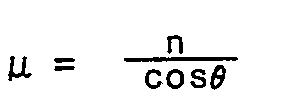
- the matrix can be represented by: where This is obtained by putting the phase thickness where (n-ik) is the complex refractive index d is the metric thickness ⁇ is the angle of the beam in the layer and ⁇ is the free space wavelength
- d the complex refractive index
- ⁇ the angle of the beam in the layer
- ⁇ the free space wavelength
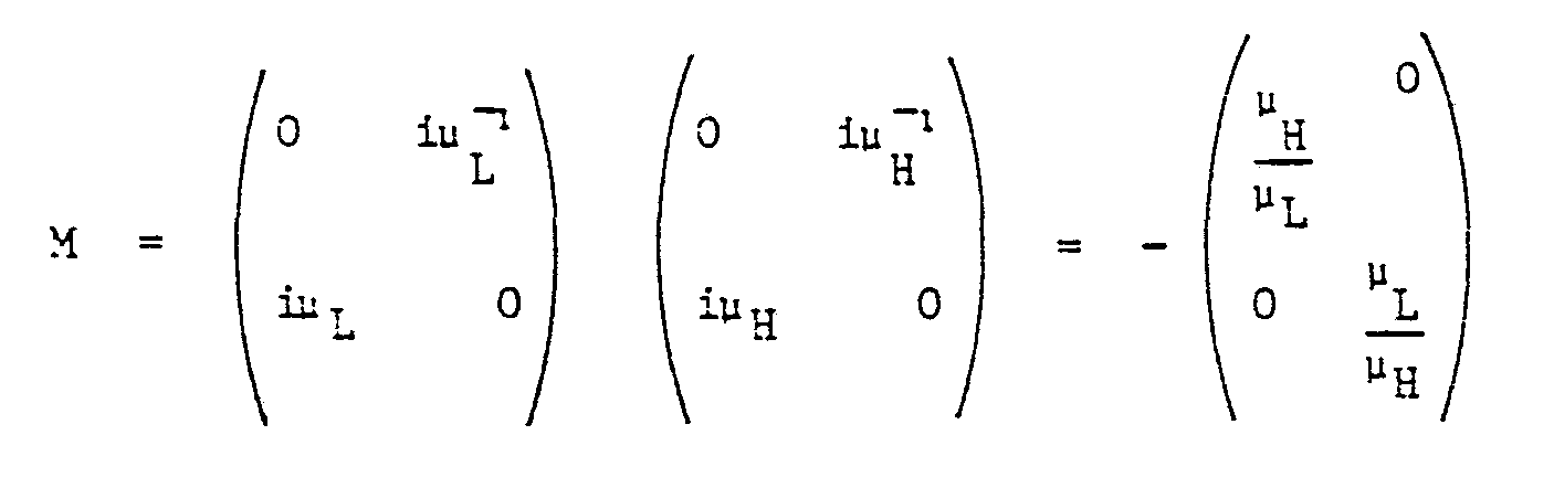
- the matrix for the stack with a lossy layer outermost and a half wave next to it can be written as:
- the second matrix on the RHS represents the matrix for a quarter wave layer because the final matrix represents a stack with a quarter wave of Si0 2 on top. This gives:
- the reflectivity R rr* is given by: since the term containing can be neglected. This gives: or, to a good approximation when A is small and ignoring squared terms and above so that the loss and for s-polarisation is As ⁇ A > ⁇ H , COS ⁇ A ⁇ COS ⁇ H
Abstract
Description
- This invention relates to mirrors and is more particularly concerned with the mirrors used in ring laser gyroscopes. As background, there are two principal modes of polarisation obtained when plane polarised light is reflected from a surface. These modes are defined by the relationship between the electric vector (E vector) of the incident light and the plane of incidence. Using the convention given in "Optical Properties of Thin Solid Films" by O.S. Heavens published by Butterworth Scientific Publications (1955), p-polarised light is defined as having the E vector in the plane of incidence and s-polarised light as having the E-vector normal to the plane of incidence. In general, if the incident radiation is p-or s-polarised, the plane of polarisation of the reflected light is unchanged. However, if the surface is made from a magneto-optically active material this does not hold. Furthermore, if the incident polarised light is polarised in any other plane than the plane of reflection, the plane of polarisation of the reflected radiation will, in general, be rotated by the reflection.
- Ring laser gyroscopes exhibit the phenomenon of "lock-in", where at low rotation rates, the two counter-rotating beams are locked to the same frequency and no frequency difference is observed until a certain higher rotation rate is attained. "Lock-in" is due to an interaction between the low lasing beams and even above the certain higher rotation rate, the effects of the interaction between the two beams is shown by the way they make the scale factor non-linear. The effect of "lock-in" can be overcome practically by providing a bias mechanism. The most commonly used method of providing this bias mechanism at present is the application of a dither frequency to the ring laser gyroscope. However, of several non-mechanical methods which have been suggested, the most attractive alternative to dither is the so-called "magnetic mirror". This was proposed in US Patent 3,851,973 and discloses the use of the magneto-optic properties of pure iron in the infrared region of the electromagnetic spectrum. Alternative "magnetic mirrors" using ferromagnetic garnet materials are disclosed in UK Patent 2006456 and US Patent 3,927,946.
- Magnetic mirrors apply a differential phase shift to the counter-rotating beams due to the transverse Kerr effect but only when the beams are p-polarised. Therefore, to utilise this phenomenon it is essential that the ring laser gyroscope should lase in a p-polarised mode. This presents no difficulty in a modular lasing cavity where the mode of polarisation is defined by the orientation of the Brewster angle windows on the discharge tube. However, an integral lasing cavity preferentially lases in the s-polarised mode because the mirrors currently employed in ring laser gyroscopes exhibit a greater reflection coefficient for s-polarised light than for p-polarised light.
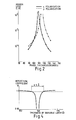
- For two dielectric materials forming an interface, the reflection coefficient, R, at the interface is greater for s-polarisation (Rs) than for p-polarisation (Rp) as illustrated in Figure A. This difference is enhanced by a multilayer dielectric mirror of the type used in ring laser gyroscopes which is made of alternating layers of two dielectric materials having different refractive indices so that the ratio Rp /Rs is always less than 1. At normal incidence, however, there is no distinction between the two polarisations. When absorption loss is taken into account the ratio of RpiRs remains less than 1 but the reflectivities for both polarisations reach an asymptotic limit as the number of layers increase. This is known as the Koppelmann limit and is illustrated in Figure B for a stack having a lossy high refractive index material with n = 2.3, and k = 5 x 10's, a non- lossy low refractive index material with n = 1.46 and an angle of incidence of 45°.
- The graph of Figure B emphasises the necessity for using more layers when formulating a mirror for reflection in the p-polarisation mode if a particular value of reflectivity is required.
- The invention involves the use of a multilayer dielectric (MLD) reflecting stack comprising alternate layers of two dielectric materials having high and low refractive indices respectively and both having low absorption. To form a mirror each layer is made to have an optical thickness of a quarter wavelength of the radiation to be reflected and taking into account the angle of incidence of the radiation.
- As is well known, such an arrangement ensures that, for both p-and s-polarised light, the beams reflected from neighbouring layer interfaces reinforce and, if a sufficient number of layers is used, very high reflectivities can be obtained. A mirror would typically be made by depositing alternate layers of titanium dioxide (Ti02) and silicon dioxide (Si02) onto a substrate of Zerodur. The initial and outermost layer being (Ti02). Typical values for the refractive indices being 2.3 to 2.4 for the Ti02 and 1.46 for the Si02. The loss coefficients, the k of the complex refractive index (n - ik), being 5 to 10 x 10-6 and 1 to 3 x 10⁻⁷ respectively.
- Generally such a mirror will have a half wave consisting of Si02 on top of the outermost Ti02 layer. This layer does nothing optically and is sometimes known as an absentee layer. Its purpose is to provide protection to the underlying Ti02 layer from the environment. Such a layer will not be considered in the following discussion, it being understood that it can be added, if desired, to any of the designs considered.
- A method which has been proposed to produce a mirror which preferentially lases in the p-polarised mode involves the use of an anti-reflection coating which is polarisation sensitive (I.M.Minkov, Optical Spectroscopy (USA), Vol.33, No.2, p.175-178). The multilayer dielectric motor so proposed comprises a repeat of a three layer anti-reflection coating which is more reflective for the p-polarised mode than for the s-polarised mode. However, the effect of absorption of light in the layers of such a mirror renders the proposal impractical.
- According to the present invention we provide a mirror comprising a multilayer dielectric (MLD) reflective stack and which is designed to enhance the reflection of p-polarised light relative to that of s-polarised light.
- Thus the present invention enables the provision of a ring laser gyroscope in which the cavity preferentially lases in the p-polarised mode so that the transverse Kerr magneto-optic effect can be utilised to prevent the occurrence of lock-in of the counter-rotating beams.
- Preferably, a mirror according to the invention is designed to enhance the absorption of s-polarised light relative to that of p-polarised light.
- This feature makes use of the fact that the dielectrics are slightly absorbing and in particular those with a high dielectric constant generally have a higher absorption coefficient than those with a low dielectric constant. At optical frequencies, the dielectric constant of a material is approximately equal to the square of the refractive index, assuming a permeability of unity. To obtain a higher reflectivity for p-polarised radiation, the MLD design is modified so that the absorption is increased preferentially for the s-polarised component to such an extent that it reduces the level of the reflectivity so that it is less than that for the p-polarised component.
- The thickness of one or more layers of the MLD reflective stack may be chosen so as to depart from optimum reflectivity.
- This can be achieved satisfactorily by making an MLD stack with the outermost layer of a quarterwave of high refractive index, the next layer having a half wave of low refractive index and the rest of the layer quarter wave. An alternative is to make the outermost layer a half wave of high refractive index and the rest quarter wave.
- Alternatively, the mirror may be designed to enhance the transmission of s-polarised light relative to that of p-polarised light. In this case, the mirror may comprise a metal layer underlying a control dielectric layer and the MLD reflective stack. In another embodiment to be described, the mirror comprises an off-tune MLD underlying a control dielectric layer and the MLD reflective stack.
- For a better understanding of the invention, reference will now be made, by way of example, to the accompanying drawings in which:-
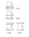
- Figure 1 is a schematic diagram of a mirror according to the invention;
- Figure 2 is a graph of mirror loss against phase thickness for both p-and s-polarised light for the mirror of Figure 1;
- Figure 3 is a schematic diagram of a mirror according to a second embodiment of the present invention;
- Figure 4 is a graph of reflection coefficient against thickness of the control layer for the mirror of figure 3;
- Figure 5 is a schematic diagram of a mirror according to a third embodiment of the present invention;
- Figure 6 is a graph of mirror loss against wavelength for the mirror of figure 5;
- Figure 7 is a schematic diagram of a fourth embodiment of the present invention; and
- Figure 8 is a graph of mirror loss against wavelength for the mirror of figure 7.
- The mirror shown in figure 1 is in the form of a Fabry-Perot filter and comprises a substrate 1 on which a gold or
silver film layer 2 is deposited. A control layer is dielectric material 3 is then formed on thefilm layer 2. On top of the control layer 3 is formed a multilayer dielectric stack 4 comprising alternate quarterwave layers made of dielectric film material. The lowest layer of the multilayer dielectric acts as a halfwave spacer while the rest of the layers make up the quarterwave reflecting stack as shown in Figure 1. For such a filter, the pass band ie. the transmission peak, is different for the p-and s-polarised modes (ignoring losses in the dielectric film layers of the stack 4) as shown in figure 2. Thus choosing the thickness of the control layer 3 can enhance transmission of s-polarised light, as indicated for example by the vertical dotted line in Figure 2, relative to that of p-polarised light thereby increasing the reflectivity of p-polarised light relative to s-polarised light. The filter of figure 1 has the main disadvantage that the thickness of the control layer 3 needs to be controlled very accurately. - In the embodiment of Figure 3, the
metallic layer 2 is replaced by a twenty layer multilayer dielectric which is off tune so that a phase shift somewhere between 0° and 180° is obtained. The use of an off-tune multilayer dielectric imparts a polarisation dependence to the mirror arrangement. - The stack of figure 3 comprises a
substrate 5 on which is formed a twenty-layer multilayer dielectric 6 which is off tune. A variable thickness layer 7 is formed on top of this dielectric and comprises a layer of garnet (TiOz). A fourteen-layer multilayer dielectric 8 is formed on top of the variable layer 7 - this layer is on tune. The reflection coefficient (R) plotted against the thickness of layer 7 is shown in figure 4 for both p-and s-polarisation modes. From the figure it can be seen that for an angle of incidence of 45°, the reflection coefficient for p-polarisation is a constant value whereas the reflectivity of s-polarisation drops off to produce a wave band around 6.5A where Rs<Rp. This arrangement also suffers from the practical difficulty of getting the pass band for s-polarisation on tune. Again Figure 4 does not include any compensation for absorption loss. When losses are considered, the width of the pass band of the Figure 3 stack is increased and makes the design more practical. - It is possible to design a multilayer dielectric having Rp>Rs by making either the first or second layer of the stack of half-wavelength thick. A thirty-five layer stack is shown in figure 5 where the stack is formed by a
multilayer dielectric 9, ahalfwave layer 10 of silicon dioxide (SiOz) and aquarterwave layer 11 of garnet all on asubstrate 12. The response of this stack is shown in figure 6 and provides a more practical solution to producing a lasing cavity which preferentially lases in the p-polarised mode. - It is thought that this embodiment works by enhancing the absorption of s-polarised light relative to that of p-polarised light. p and s-polarised light set up different types of standing wave in a MLD reflective stack. The standing wave for s-polarised light is of continuous relatively simply sinusoidal form whereas that for p-polarised light is of a discontinuous and complex form. In this embodiment according to the invention, this difference is exploited by arranging the mirror so that absorption is enhanced where this will most affect s-polarised light ie . at the intensity maxima of the s-polarised light standing wave.
- In practice it is found that maximising absorption of s-polarised light also helps to maximise the differential phase shift applied to counter-rotating laser beams when a suitable magneto-optic layer, such as a layer of garnet material, is included in the mirror.
- By providing less layers in the MLD reflecting stack a transmitting mirror can be produced as shown in Figure 7 in which the
MLD 13 comprises twenty seven layers mounted on asubstrate 14. A half-wavelength dielectric layer 15 of high refractive index overlies theMLD 13, the top layer of which is a quarter wave layer of low refractive index - The results obtained are shown in Figure 8 showing that Rp>Rs in the
approximate waveband 620 to 645 nm. - It has been found that using a half-wavelength layer further down in the MLD stack for a transmitting mirror enables a greater difference between the reflectivities of p-and s-polarised light to be obtained but over a relatively narrower waveband.
- The results referred to are obtained using a standard computer program for MLD devices. The results shown in figures 2, 4, 6 and 8 are for an angle of incidence of 45°, but naturally other angles of incidence are possible with corresponding modifications of the graphs to allow for changes in absorption in the dielectric materials used.
- An appendix follows which provides an analytical approach for a simple case showing the effect of incorporating a half-wavelength layer of low refractive index next to the top of an MLD reflective stack.
- Using the notation of Liddell (181) the matrix for a pair of dielectrics having no loss and an optical thickness of k/4 is


- If the outermost layer of the stack is a λ/4 layer with loss, assumed small, the matrix can be represented by:


isin 2 sinhΔ ≃ iΔ when k is small

- The matrix for the stack with a lossy layer outermost and a half wave next to it can be written as:

- The second matrix on the RHS represents the matrix for a quarter wave layer because the final matrix represents a stack with a quarter wave of Si02 on top. This gives:

- Using the standard notation the E field in front of the MLD is given by:


- The reflection coefficient

- The reflectivity R = rr* is given by:


- Hence the loss for p-polarisated light is less than that for s-polarised light.
Claims (13)
Applications Claiming Priority (2)
| Application Number | Priority Date | Filing Date | Title |
|---|---|---|---|
| GB868621510A GB8621510D0 (en) | 1986-09-06 | 1986-09-06 | Ring laser gyroscopes |
| GB8621510 | 1986-09-06 |
Publications (3)
| Publication Number | Publication Date |
|---|---|
| EP0267672A2 true EP0267672A2 (en) | 1988-05-18 |
| EP0267672A3 EP0267672A3 (en) | 1988-08-03 |
| EP0267672B1 EP0267672B1 (en) | 1993-10-20 |
Family
ID=10603787
Family Applications (1)
| Application Number | Title | Priority Date | Filing Date |
|---|---|---|---|
| EP87307424A Expired - Lifetime EP0267672B1 (en) | 1986-09-06 | 1987-08-21 | Mirrors of polarization sensitive reflectivity |
Country Status (5)
| Country | Link |
|---|---|
| US (1) | US4900137A (en) |
| EP (1) | EP0267672B1 (en) |
| JP (1) | JPS6392902A (en) |
| DE (1) | DE3787869T2 (en) |
| GB (1) | GB8621510D0 (en) |
Cited By (4)
| Publication number | Priority date | Publication date | Assignee | Title |
|---|---|---|---|---|
| FR2636133A1 (en) * | 1988-09-02 | 1990-03-09 | Northrop Corp | LASER GYROSCOPE IN RING AND MAGNETIC MIRROR FOR THIS GYROSCOPE |
| EP0451618A1 (en) * | 1990-03-30 | 1991-10-16 | Honeywell Inc. | Method for producing multilayer optical interference coatings |
| US5137358A (en) * | 1991-02-05 | 1992-08-11 | Northrop Corporation | Ring laser gyro having two magnetic mirrors |
| CN113359220A (en) * | 2021-06-10 | 2021-09-07 | 浙江大学 | Spectral filter based on three-dimensional annular structure and application |
Families Citing this family (13)
| Publication number | Priority date | Publication date | Assignee | Title |
|---|---|---|---|---|
| WO1989008278A1 (en) * | 1988-02-26 | 1989-09-08 | Fujitsu Limited | Polarizing isolation apparatus and optical isolator using the same |
| US5548602A (en) * | 1994-06-30 | 1996-08-20 | Honeywell Inc. | Method and structure for reflecting 633 nm radiation while eliminating 650 nm radiation in ring laser gyro mirrors |
| US5646780A (en) * | 1994-08-24 | 1997-07-08 | Honeywell Inc. | Overcoat method and apparatus for ZRO2 mirror stacks |
| US5926317A (en) * | 1996-11-06 | 1999-07-20 | Jds Fitel Inc. | Multilayer thin film dielectric bandpass filter |
| US6665120B2 (en) * | 1998-09-16 | 2003-12-16 | Canon Kabushiki Kaisha | Reflective optical element |
| DE60130777T2 (en) * | 2000-08-21 | 2008-07-17 | 3M Innovative Properties Co., Saint Paul | REFLECTIVE OPTICAL FILTERS WITH LOSS OPTIMIZATION |
| JP2004088049A (en) * | 2002-03-08 | 2004-03-18 | Mitsubishi Electric Corp | Optical semiconductor device |
| EP1431824A1 (en) * | 2002-12-18 | 2004-06-23 | ASML Netherlands B.V. | Lithographic apparatus, device manufacturing method, and device manufactured thereby |
| KR20050001425A (en) * | 2003-06-27 | 2005-01-06 | 아사히 가라스 가부시키가이샤 | High reflectance mirror |
| US9389080B2 (en) * | 2014-01-08 | 2016-07-12 | Honeywell International Inc. | Ring laser gyroscope with integrated polarization |
| US20190324175A1 (en) * | 2018-04-18 | 2019-10-24 | Honeywell International Inc. | Methods for enhancing the durability and manufacturability of multilayer interference mirrors |
| US11962118B2 (en) | 2020-10-27 | 2024-04-16 | Honeywell International Inc. | Ultraviolet filter for ring laser gyroscope mirrors |
| CN114114488B (en) * | 2021-11-10 | 2023-09-12 | 中国科学院上海技术物理研究所 | Visible near infrared metal film reflector with adjustable polarization sensitivity |
Citations (6)
| Publication number | Priority date | Publication date | Assignee | Title |
|---|---|---|---|---|
| US3851973A (en) * | 1972-01-03 | 1974-12-03 | Sperry Rand Corp | Ring laser magnetic bias mirror compensated for non-reciprocal loss |
| DE2400346A1 (en) * | 1974-01-04 | 1975-07-17 | Sperry Rand Corp | Ring laser closed loop optical cavity system - has light reflecting frequency biasing element for phase shift imparting |
| US4009933A (en) * | 1975-05-07 | 1977-03-01 | Rca Corporation | Polarization-selective laser mirror |
| GB2020842A (en) * | 1978-05-15 | 1979-11-21 | Sperry Rand Corp | Magnetic mirror for imparting nonreciprocal phase shift |
| DE2939463A1 (en) * | 1978-09-29 | 1980-04-10 | Canon Kk | PHASE SHIFT MIRROR |
| DE3207730A1 (en) * | 1982-03-04 | 1983-09-08 | Teldix Gmbh, 6900 Heidelberg | Ring laser |
Family Cites Families (5)
| Publication number | Priority date | Publication date | Assignee | Title |
|---|---|---|---|---|
| US3427089A (en) * | 1965-03-12 | 1969-02-11 | Webb James E | Ultraviolet filter |
| US3927946A (en) * | 1968-03-21 | 1975-12-23 | Sperry Rand Corp | Ring laser frequency biasing mechanism |
| GB2006456B (en) * | 1977-10-04 | 1983-06-02 | Sperry Rand Ltd | Magneto-optical phase modulatiing devices |
| JPS59172176A (en) * | 1983-03-22 | 1984-09-28 | Nippon Kogaku Kk <Nikon> | Photomagnetic recording and reproducing device |
| JPS60169804A (en) * | 1984-02-14 | 1985-09-03 | Fujitsu Ltd | Polarization separation film |
-
1986
- 1986-09-06 GB GB868621510A patent/GB8621510D0/en active Pending
-
1987
- 1987-08-21 EP EP87307424A patent/EP0267672B1/en not_active Expired - Lifetime
- 1987-08-21 DE DE87307424T patent/DE3787869T2/en not_active Expired - Fee Related
- 1987-08-26 US US07/089,399 patent/US4900137A/en not_active Expired - Fee Related
- 1987-09-04 JP JP62220572A patent/JPS6392902A/en active Pending
Patent Citations (6)
| Publication number | Priority date | Publication date | Assignee | Title |
|---|---|---|---|---|
| US3851973A (en) * | 1972-01-03 | 1974-12-03 | Sperry Rand Corp | Ring laser magnetic bias mirror compensated for non-reciprocal loss |
| DE2400346A1 (en) * | 1974-01-04 | 1975-07-17 | Sperry Rand Corp | Ring laser closed loop optical cavity system - has light reflecting frequency biasing element for phase shift imparting |
| US4009933A (en) * | 1975-05-07 | 1977-03-01 | Rca Corporation | Polarization-selective laser mirror |
| GB2020842A (en) * | 1978-05-15 | 1979-11-21 | Sperry Rand Corp | Magnetic mirror for imparting nonreciprocal phase shift |
| DE2939463A1 (en) * | 1978-09-29 | 1980-04-10 | Canon Kk | PHASE SHIFT MIRROR |
| DE3207730A1 (en) * | 1982-03-04 | 1983-09-08 | Teldix Gmbh, 6900 Heidelberg | Ring laser |
Non-Patent Citations (2)
| Title |
|---|
| JOURNAL OF THE OPTICAL SOCIETY OF AMERICA.A.OPTICS AND IMAGE SCIENCE, vol. 1, July 1984, pages 699-702, New York, US; R.M.A. AZZAM "Inverting the ratio of the complex parallel and perpendicular reflection coefficients of an absorbing substrate using a transparent thin-film coating" * |
| McGraw-Hill encyclopedia of science and technology, pp. 43, 44 and 233 * |
Cited By (6)
| Publication number | Priority date | Publication date | Assignee | Title |
|---|---|---|---|---|
| FR2636133A1 (en) * | 1988-09-02 | 1990-03-09 | Northrop Corp | LASER GYROSCOPE IN RING AND MAGNETIC MIRROR FOR THIS GYROSCOPE |
| US4968136A (en) * | 1988-09-02 | 1990-11-06 | Northrop Corporation | Ring laser gyro and magnetic mirror therefor |
| EP0451618A1 (en) * | 1990-03-30 | 1991-10-16 | Honeywell Inc. | Method for producing multilayer optical interference coatings |
| US5137358A (en) * | 1991-02-05 | 1992-08-11 | Northrop Corporation | Ring laser gyro having two magnetic mirrors |
| CN113359220A (en) * | 2021-06-10 | 2021-09-07 | 浙江大学 | Spectral filter based on three-dimensional annular structure and application |
| CN113359220B (en) * | 2021-06-10 | 2022-04-19 | 浙江大学 | Spectral filter based on three-dimensional annular structure and application |
Also Published As
| Publication number | Publication date |
|---|---|
| DE3787869D1 (en) | 1993-11-25 |
| US4900137A (en) | 1990-02-13 |
| EP0267672B1 (en) | 1993-10-20 |
| DE3787869T2 (en) | 1994-02-10 |
| GB8621510D0 (en) | 1986-10-15 |
| JPS6392902A (en) | 1988-04-23 |
| EP0267672A3 (en) | 1988-08-03 |
Similar Documents
| Publication | Publication Date | Title |
|---|---|---|
| EP0267672A2 (en) | Mirrors of polarization sensitive reflectivity | |
| US5513039A (en) | Ultraviolet resistive coated mirror and method of fabrication | |
| US4525028A (en) | Enhanced magnetic mirror | |
| Sharon et al. | Narrow spectral bandwidths with grating waveguide structures | |
| EP0626596B1 (en) | Ultraviolet resistive antireflective coating | |
| US5198930A (en) | Wide-band half-mirror | |
| EP0647995B1 (en) | Optimizing output characteristics of a tunable external cavity laser | |
| JPS6037631B2 (en) | Argon ion laser device | |
| US6256434B1 (en) | Method and dielectric and/or semiconductor device for influencing the dispersion of electromagnetic radiation | |
| JPH0117275B2 (en) | ||
| US5604629A (en) | Discrete vacuum ultra violet reflective interference filter | |
| US6487227B1 (en) | Semiconductor laser | |
| US7145722B2 (en) | Optical filter and method of manufacturing thereof | |
| US5835273A (en) | High reflectivity, broad band mirror and process for producing such a mirror | |
| US5608577A (en) | Optical mirror and optical device using the same | |
| JPH0856049A (en) | Surface emitting laser | |
| US5978141A (en) | Optical mirror particularly suited for a quantum well mirror | |
| US5272332A (en) | Laser discrimination device | |
| US4340969A (en) | Laser apparatus | |
| US4932754A (en) | Multilayer optical component | |
| GB2192070A (en) | Optical attenuator | |
| KR100990324B1 (en) | Polarization independent optical taps | |
| CA1178701A (en) | Enhanced magnetic mirror configuration | |
| KR960013804B1 (en) | Polarization switching system | |
| Poitras et al. | Spectral Asymmetry in Waveguide Facet Coatings |
Legal Events
| Date | Code | Title | Description |
|---|---|---|---|
| PUAI | Public reference made under article 153(3) epc to a published international application that has entered the european phase |
Free format text: ORIGINAL CODE: 0009012 |
|
| 17P | Request for examination filed |
Effective date: 19870826 |
|
| AK | Designated contracting states |
Kind code of ref document: A2 Designated state(s): DE FR GB NL |
|
| PUAL | Search report despatched |
Free format text: ORIGINAL CODE: 0009013 |
|
| AK | Designated contracting states |
Kind code of ref document: A3 Designated state(s): DE FR GB NL |
|
| 17Q | First examination report despatched |
Effective date: 19910131 |
|
| RAP3 | Party data changed (applicant data changed or rights of an application transferred) |
Owner name: BRITISH AEROSPACE PUBLIC LIMITED COMPANY |
|
| GRAA | (expected) grant |
Free format text: ORIGINAL CODE: 0009210 |
|
| AK | Designated contracting states |
Kind code of ref document: B1 Designated state(s): DE FR GB NL |
|
| REF | Corresponds to: |
Ref document number: 3787869 Country of ref document: DE Date of ref document: 19931125 |
|
| ET | Fr: translation filed | ||
| PLBE | No opposition filed within time limit |
Free format text: ORIGINAL CODE: 0009261 |
|
| STAA | Information on the status of an ep patent application or granted ep patent |
Free format text: STATUS: NO OPPOSITION FILED WITHIN TIME LIMIT |
|
| 26N | No opposition filed | ||
| PGFP | Annual fee paid to national office [announced via postgrant information from national office to epo] |
Ref country code: FR Payment date: 19970811 Year of fee payment: 11 |
|
| PGFP | Annual fee paid to national office [announced via postgrant information from national office to epo] |
Ref country code: GB Payment date: 19970815 Year of fee payment: 11 |
|
| PGFP | Annual fee paid to national office [announced via postgrant information from national office to epo] |
Ref country code: DE Payment date: 19970818 Year of fee payment: 11 |
|
| PGFP | Annual fee paid to national office [announced via postgrant information from national office to epo] |
Ref country code: NL Payment date: 19970821 Year of fee payment: 11 |
|
| PG25 | Lapsed in a contracting state [announced via postgrant information from national office to epo] |
Ref country code: GB Free format text: LAPSE BECAUSE OF NON-PAYMENT OF DUE FEES Effective date: 19980821 |
|
| PG25 | Lapsed in a contracting state [announced via postgrant information from national office to epo] |
Ref country code: NL Free format text: LAPSE BECAUSE OF NON-PAYMENT OF DUE FEES Effective date: 19990301 |
|
| GBPC | Gb: european patent ceased through non-payment of renewal fee |
Effective date: 19980821 |
|
| PG25 | Lapsed in a contracting state [announced via postgrant information from national office to epo] |
Ref country code: FR Free format text: LAPSE BECAUSE OF NON-PAYMENT OF DUE FEES Effective date: 19990430 |
|
| NLV4 | Nl: lapsed or anulled due to non-payment of the annual fee |
Effective date: 19990301 |
|
| PG25 | Lapsed in a contracting state [announced via postgrant information from national office to epo] |
Ref country code: DE Free format text: LAPSE BECAUSE OF NON-PAYMENT OF DUE FEES Effective date: 19990601 |
|
| REG | Reference to a national code |
Ref country code: FR Ref legal event code: ST |