EP0266684B1 - Method and dryer comprising an apparatus for the regeneration of a drying cartridge impregnated with moisture - Google Patents
Method and dryer comprising an apparatus for the regeneration of a drying cartridge impregnated with moisture Download PDFInfo
- Publication number
- EP0266684B1 EP0266684B1 EP87115942A EP87115942A EP0266684B1 EP 0266684 B1 EP0266684 B1 EP 0266684B1 EP 87115942 A EP87115942 A EP 87115942A EP 87115942 A EP87115942 A EP 87115942A EP 0266684 B1 EP0266684 B1 EP 0266684B1
- Authority
- EP
- European Patent Office
- Prior art keywords
- drying
- cartridge
- air
- circuit
- regeneration
- Prior art date
- Legal status (The legal status is an assumption and is not a legal conclusion. Google has not performed a legal analysis and makes no representation as to the accuracy of the status listed.)
- Expired - Lifetime
Links
- 238000001035 drying Methods 0.000 title claims abstract description 184
- 238000000034 method Methods 0.000 title claims abstract description 31
- 230000008929 regeneration Effects 0.000 title abstract description 75
- 238000011069 regeneration method Methods 0.000 title abstract description 75
- 230000001172 regenerating effect Effects 0.000 claims abstract description 16
- 239000000463 material Substances 0.000 claims abstract description 14
- 238000001816 cooling Methods 0.000 claims description 25
- 238000010438 heat treatment Methods 0.000 claims description 21
- 239000000843 powder Substances 0.000 abstract description 7
- 239000008187 granular material Substances 0.000 abstract description 6
- 229920003023 plastic Polymers 0.000 abstract description 2
- 239000004033 plastic Substances 0.000 abstract description 2
- 238000009413 insulation Methods 0.000 description 3
- 239000007788 liquid Substances 0.000 description 3
- 229920006395 saturated elastomer Polymers 0.000 description 3
- 239000003463 adsorbent Substances 0.000 description 2
- 238000001704 evaporation Methods 0.000 description 2
- 230000008020 evaporation Effects 0.000 description 2
- 230000000717 retained effect Effects 0.000 description 2
- 239000002918 waste heat Substances 0.000 description 2
- XLYOFNOQVPJJNP-UHFFFAOYSA-N water Substances O XLYOFNOQVPJJNP-UHFFFAOYSA-N 0.000 description 2
- 229920000426 Microplastic Polymers 0.000 description 1
- 238000007664 blowing Methods 0.000 description 1
- 238000010924 continuous production Methods 0.000 description 1
- 239000000428 dust Substances 0.000 description 1
- 238000005265 energy consumption Methods 0.000 description 1
- 230000001771 impaired effect Effects 0.000 description 1
- 239000002808 molecular sieve Substances 0.000 description 1
- 230000000630 rising effect Effects 0.000 description 1
- URGAHOPLAPQHLN-UHFFFAOYSA-N sodium aluminosilicate Chemical compound [Na+].[Al+3].[O-][Si]([O-])=O.[O-][Si]([O-])=O URGAHOPLAPQHLN-UHFFFAOYSA-N 0.000 description 1
Images


Classifications
-
- F—MECHANICAL ENGINEERING; LIGHTING; HEATING; WEAPONS; BLASTING
- F26—DRYING
- F26B—DRYING SOLID MATERIALS OR OBJECTS BY REMOVING LIQUID THEREFROM
- F26B21/00—Arrangements or duct systems, e.g. in combination with pallet boxes, for supplying and controlling air or gases for drying solid materials or objects
- F26B21/06—Controlling, e.g. regulating, parameters of gas supply
- F26B21/08—Humidity
- F26B21/083—Humidity by using sorbent or hygroscopic materials, e.g. chemical substances, molecular sieves
-
- B—PERFORMING OPERATIONS; TRANSPORTING
- B01—PHYSICAL OR CHEMICAL PROCESSES OR APPARATUS IN GENERAL
- B01D—SEPARATION
- B01D53/00—Separation of gases or vapours; Recovering vapours of volatile solvents from gases; Chemical or biological purification of waste gases, e.g. engine exhaust gases, smoke, fumes, flue gases, aerosols
- B01D53/26—Drying gases or vapours
- B01D53/261—Drying gases or vapours by adsorption
-
- B—PERFORMING OPERATIONS; TRANSPORTING
- B29—WORKING OF PLASTICS; WORKING OF SUBSTANCES IN A PLASTIC STATE IN GENERAL
- B29B—PREPARATION OR PRETREATMENT OF THE MATERIAL TO BE SHAPED; MAKING GRANULES OR PREFORMS; RECOVERY OF PLASTICS OR OTHER CONSTITUENTS OF WASTE MATERIAL CONTAINING PLASTICS
- B29B13/00—Conditioning or physical treatment of the material to be shaped
- B29B13/06—Conditioning or physical treatment of the material to be shaped by drying
- B29B13/065—Conditioning or physical treatment of the material to be shaped by drying of powder or pellets
-
- F—MECHANICAL ENGINEERING; LIGHTING; HEATING; WEAPONS; BLASTING
- F26—DRYING
- F26B—DRYING SOLID MATERIALS OR OBJECTS BY REMOVING LIQUID THEREFROM
- F26B21/00—Arrangements or duct systems, e.g. in combination with pallet boxes, for supplying and controlling air or gases for drying solid materials or objects
- F26B21/02—Circulating air or gases in closed cycles, e.g. wholly within the drying enclosure
- F26B21/04—Circulating air or gases in closed cycles, e.g. wholly within the drying enclosure partly outside the drying enclosure
-
- B—PERFORMING OPERATIONS; TRANSPORTING
- B29—WORKING OF PLASTICS; WORKING OF SUBSTANCES IN A PLASTIC STATE IN GENERAL
- B29B—PREPARATION OR PRETREATMENT OF THE MATERIAL TO BE SHAPED; MAKING GRANULES OR PREFORMS; RECOVERY OF PLASTICS OR OTHER CONSTITUENTS OF WASTE MATERIAL CONTAINING PLASTICS
- B29B9/00—Making granules
- B29B9/16—Auxiliary treatment of granules
Definitions
- the invention relates to a method for regenerating a moisture-laden drying cartridge according to the preamble of claim 1 and a dryer with a regeneration device for carrying out such a method according to claim 5.
- Drying cartridges are used to prepare drying air for drying plastics, which can be in the form of granules and powder.
- the drying air is first passed through the material to be dried, the drying air absorbing moisture from the material.
- This air which is laden with moisture, is then passed through the drying cartridge, which absorbs the moisture from the drying air.
- the drying air then returns to the material to be dried. This drying process is continued until the drying cartridge can absorb almost no moisture from the drying air.
- Continuous processes use several, usually two to four drying cartridges, one of which is always regenerated. This means that there are always enough drying cartridges available.
- the drying cartridge to be regenerated must be cooled after the regeneration before it can be used again to dry the material.
- the heating device is switched off in the known method and only the cool atmospheric air is guided through the dried drying cartridge. This atmospheric air partially humidifies the drying cartridge, so that the efficiency of the dryer operating according to this method is impaired.
- the air Before entering the drying cartridge, the air has a temperature of around 320 ° C, while after the moisture has separated in the cooler / condenser it has cooled to around 40 ° C. Therefore, the air must be heated from about 40 ° C to about 320 ° C each time it goes through the circuit. For the subsequent cooling of the regenerated drying cartridge, the heating device is switched off and the air continues to be conducted in a closed circuit, as a result of which the drying cartridge is cooled. A high energy expenditure is therefore necessary for the regeneration of the drying cartridge.
- the invention has for its object to design the generic method and the dryer so that an optimal lowest possible dew point is achieved after the regeneration of the cartridge, the energy required for the regeneration should be as small as possible.
- the regeneration air is conducted in the closed regeneration circuit through the drying cartridge to be regenerated.
- the regeneration air is circulated until it is saturated with moisture or the drying cartridge is dry. If the drying cartridge is not completely dry when the regeneration air is saturated, fresh atmospheric air is fed back into the closed circuit for further drying. This process is repeated until the drying cartridge is dry. Then the regeneration air is blown out.
- the regeneration air When passing through the drying cartridge to be regenerated, the regeneration air only loses as much energy as it needs to heat up the drying cartridge and to evaporate the moisture in the drying cartridge. It is therefore essential to supply the evaporation energy of the regeneration air flowing in the circuit. This means that a very low, optimal dew point can be achieved with the least amount of energy, so that the regenerated drying cartridge delivers optimal results when the material is subsequently dried.
- the drying cartridge which was dried during the regeneration and heated in the process, is then cooled by the new atmospheric air, which is also fed through the drying cartridge in a closed regeneration circuit.
- the recooling energy released when this air is repeatedly cooled can be used economically via a heat exchanger, for example for heating the drying air which is used to dry the material. However, it is also possible to economically dissipate the energy released during repeated cooling.
- the heat exchanger is switched by the control element into the closed regeneration circuit, which is separate from the drying circuit, during the cooling of the regenerated drying cartridge.
- the regeneration air absorbs heat as it flows through the dried drying cartridge, which cools it.
- the heated air emerging from the drying cartridge flows through the heat exchanger and releases its heat in the process.
- the drying cartridge can be cooled to the required temperature after drying so that it can be switched back into the drying cycle.
- the heat absorbed by the heat exchanger from the cooling air can be used in a suitable manner. In this way, the drying cartridges can be regenerated with the least energy loss and the least energy expenditure using the dryer according to the invention.
- drying air material located in a drying container 1, preferably plastic granules or powder, is dried by means of dry air, so-called drying air.
- the mouth 4 of the feed line 2 lies in the region of the bottom of the drying container, so that the dry air emerging from it flows upward in the drying container in the direction of the arrows shown.
- In the upper area of the drying container 1 there is an outlet 5 to which a return line 6 is connected.
- a filter 7 In it there is a filter 7 in order to collect dust and the like contained in the drying air flowing from the drying container.
- the return line 6 there is also a blower 8 which lies between the filter 7 and a drying cartridge 9 into which the return line 6 opens.
- the feed line 2 is also connected to the drying cartridge 9.
- the heating device 3 is located in the flow direction behind the drying cartridge, which is preferably a molecular sieve cartridge.
- the powder or granules to be dried are found in the drying container 1.
- the drying air flows via the feed line 2 into the drying container 1 and flows through the granules or the powder.
- the drying air absorbs moisture from the granules or powder and flows via the return line 6 and the filter 7 into the drying cartridge 9, where the moisture absorbed by the drying air is retained, so that dry air again reaches the drying container 1 via the supply line 2 .
- the drying air in the supply line 2 is heated to the required temperature with the heating device 3.
- the drying air is thus conducted in a drying circuit 10, the powder or the granules being dried to the desired extent.
- only one drying cartridge 9 is shown in the drying circuit 10. Of course, it is possible to use several drying cartridges 9 in the drying circuit 10.
- the drying air is circulated until the material to be dried in the container 1 is sufficiently dehumidified.
- the drying cartridge 9 is exhausted and can only absorb a little moisture from the drying air, it is regenerated.
- the device is provided with a regeneration circuit 11 in which the cartridge 9 ⁇ to be regenerated lies.
- a line 12 is connected to it, which, as shown only schematically in FIG. 1a with the aid of a line branch 16, is surrounded by insulation 13. All lines are preferably insulated from the atmosphere separately.
- a blower 14 In the flow direction of the regeneration air behind the cartridge 9 ⁇ to be regenerated there is a blower 14 and a heating device 15 in the line 12. It lies between the blowers 14 and the cartridge 9 ⁇ .
- the line 12 also has a line branch 16a in which there is a heat exchanger 17, which is preferably also insulated from the outside.
- the line branch 16a can be opened or closed via a valve 18.
- the line branch 16a is closed, so that the regeneration air flows in the regeneration circuit 11 in the direction of the arrows shown.
- the regeneration circuit 11 dry air is passed through the cartridge 9 ⁇ , this air absorbing the moisture from the cartridge 9 ⁇ and thus drying it.
- the water in the cartridge 9 ⁇ must be transferred in vapor form. Therefore, the regeneration air with the heating device 15 is heated so strongly before entering the cartridge 9 ⁇ (to about 180 ° C to 250 ° C) that the liquid in the cartridge 9 Concretet is converted into vapor form and can thus be absorbed by it.
- the air emerging from the cartridge 9 ⁇ has cooled due to the transfer of the liquid into the vapor form, so that the heating device 15 heats the air again by this amount of cooling before entering the cartridge 9 Patr.
- This temperature difference corresponds essentially only to the evaporation energy which is necessary to convert the liquid in the cartridge 9 ⁇ into the vapor form. Since no atmospheric air gets into the regeneration circuit 11 during the drying process described, the cartridge 9 'can be optimally dehumidified in the regeneration circuit 11.
- the insulation 13 ensures that the heat losses when flowing through the line 12 are low, so that the heating device 15 only needs to heat the regeneration air a little.
- the closed regeneration circuit 11 allows the water in the cartridge 9 ⁇ to be evaporated practically without loss of energy.
- a valve 19 is installed, which has such a position in Fig. 1a that the drying air in the line 6 of the drying cartridge 9 and the regeneration air after leaving the cartridge to be regenerated 9 ⁇ of the heating device 15 is fed via the blower 14.
- the line 12 is opened briefly so that the regeneration air, which is now laden with moisture, can escape from the regeneration circuit 11.
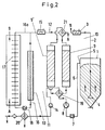
- an outlet valve 20 is provided in the line 12 after the blower 14 and is opened in this case (FIG. 2).
- atmospheric new air flows at "X" into line 12, which can then be used to dry again after the outlet valve has been closed.
- the same or a different drying cartridge 9 ⁇ can now be dried in the manner described.
- the atmospheric air is slightly laden with moisture, the proportion of moisture within the regeneration circuit 11 is small because new atmospheric air is not continuously added during the regeneration process, but is instead conducted in a closed circuit.
- the line branch 16 a remains closed during the blowing out of the used regeneration air and the drawing in of new atmospheric air.
- Fig.2 When the cartridge 9 ⁇ has dried in the regeneration circuit 11, it can generally not be switched immediately into the drying circuit 10 because it has been heated by the hot regeneration air during the regeneration process. The cartridge 9 ⁇ is too hot after regeneration, so that it must be cooled.
- the heating device 15 in the regeneration circuit 11 is switched off or, by switching the valve 18, is placed in the line part 16, through which cooling air does not flow (FIG. 3). This has the advantage that the heat content contained in the heating device 15 is largely retained.
- the line branch 16a is opened via the valves 20, 18, so that the regeneration air in the direction of the arrows in Fig.
- the control valve 18 must be used instead of a changeover valve in the regeneration circuit 11 for the changeover from the heating phase to the recooling phase.
- a switching flap can also be provided instead of the control valve 18. It is closed after a first switchover to the heat exchanger 17 whenever the temperature in the drying circuit 10 exceeds the desired setpoint value and is switched over as soon as this temperature falls below again.
- the cartridge 9 ⁇ Since the air is recirculated during recooling, ie atmospheric, moisture-laden air is not continuously added, the cartridge 9 ⁇ is not already loaded with moisture during this cooling process. This procedure achieves an extremely low dew point, which is of the order of about -50 ° C to -70 ° C. The regeneration described thus ensures optimum efficiency reached the device.
- the cartridge 9 ⁇ When the cartridge 9 ⁇ has been cooled to the required temperature, it can be switched into the drying circuit 10 (Fig. 1b; now cartridge 9), so that it in turn the drying air conveyed in this circuit after passing through the material to be dried in the drying container 1 can dehumidify in the manner described.
- the described cooling of the regenerated cartridge 9 ⁇ is necessary if it is hotter than the inlet temperature of the air flowing in the drying circuit 10 when it enters the drying cartridge 9.
- the heat exchanger 17 is a known air-air exchanger.
- the waste heat emitted by the heat exchanger 17 during cooling can be used to heat the air in the drying circuit 10 or for other purposes. With the waste heat, the air in the drying circuit 10 can be heated when it has a certain minimum temperature, which, for. B. is about 70 ° C. In this case, the air in the drying circuit 10 can also be passed through the heat exchanger 17, whereby it absorbs the heat given off by it. As a result, the energy consumption of the device can be kept low.
- valve 19 and a valve 21 are used in a known manner, which are installed in the lines 6 and 12.
- the valve 21 is located in the flow direction of the drying air behind the cartridge 9 and in the flow direction of the regeneration air in front of the cartridge 9 ⁇ (Fig.1a).
- flaps, rotary valves (rotary carousel) and the like can also be used.
- a continuous drying process is possible (Fig. 1a, 1b).
- the other cartridge 9 ⁇ can be regenerated in the regeneration circuit 11.
- the cartridge 9 ⁇ regenerated in the regeneration circuit 11 can be switched into the drying circuit (now cartridge 9; Fig. 1b) and the exhausted drying cartridge 9 (now cartridge 9 '; Fig. 1b) in the regeneration circuit 11 will.
- Further drying cartridges can be provided in the drying circuit 10.
- FIG. 4 shows one possibility of how the heat given off to the heat exchanger 17 can be used to heat the air flowing in the drying circuit 10.
- the air After exiting the drying cartridge 9, the air must be heated up again to the respective temperature.
- the drying air is not again passed directly over the heating device 3, but over the heat exchanger 17.
- the heat exchanger 17 absorbs the heat of the air flowing for cooling in the regeneration circuit 11. This heat is absorbed by the air in the drying circuit 10, which flows past the heat exchanger 17.
- the drying air is already heated after passing through the drying cartridge 9, so that it only needs to be heated up a little with the heating device 3.
- the energy present in the cartridge 9 ' is transferred via the heat exchanger 17 to the drying circuit 10 so that the valve 18 divides the regeneration circuit 11 so that a partial flow via the heat exchanger 17 in the line branch 16a and another partial flow via the line branch 16 (when switched off Heating 15) is performed.
- the one partial flow flowing over the heat exchanger 17 should only be so great that the temperature on the drying circuit 10 does not exceed the desired value (when the heater 3 is switched off).
- the Valve 18 can also be switched so that it leads the regeneration circuit 11 via the branch line 16a or 16 at short intervals in accordance with the energy requirement in the drying circuit 10.
Landscapes
- Engineering & Computer Science (AREA)
- Chemical & Material Sciences (AREA)
- Mechanical Engineering (AREA)
- Chemical Kinetics & Catalysis (AREA)
- General Chemical & Material Sciences (AREA)
- General Engineering & Computer Science (AREA)
- Analytical Chemistry (AREA)
- Oil, Petroleum & Natural Gas (AREA)
- Drying Of Solid Materials (AREA)
- Processing And Handling Of Plastics And Other Materials For Molding In General (AREA)
- Drying Of Gases (AREA)
- Coating Apparatus (AREA)
- Photographic Developing Apparatuses (AREA)
- Automatic Disk Changers (AREA)
- Packaging Of Annular Or Rod-Shaped Articles, Wearing Apparel, Cassettes, Or The Like (AREA)
Abstract
Description
Die Erfindung betrifft ein Verfahren zum Regenerieren einer mit Feuchtigkeit beladenen Trocknungspatrone nach dem Oberbegriff des Anspruches 1 sowie einen Trockner mit einer Regeneriervorrichtung zur Durchführung eines solchen Verfahrens nach Anspruch 5.The invention relates to a method for regenerating a moisture-laden drying cartridge according to the preamble of
Für die Aufbereitung von Trocknungsluft zur Trocknung von Kunststoffen, die in Form von Granulaten und Pulver vorliegen können, werden Trocknungspatronen verwendet. Die Trocknungsluft wird zunächst durch das zu trocknende Gut geführt, wobei die Trocknungsluft Feuchtigkeit aus dem Gut aufnimmt. Anschließend wird diese mit Feuchtigkeit beladene Luft durch die Trocknungspatrone geführt, welche die Feuchtigkeit aus der Trocknungsluft aufnimmt. Anschließend gelangt die Trocknungsluft wieder zum zu trocknenden Gut. Dieser Trocknungsprozeß wird so lange fortgeführt, bis die Trocknungspatrone nahezu keine Feuchtigkeit mehr aus der Trocknungsluft aufnehmen kann. Bei kontinuierlich arbeitenden Verfahren werden mehrere, meistens zwei bis vier Trocknungspatronen verwendet, von denen eine stets regeneriert wird. Dadurch stehen immer ausreichend viele Trocknungspatronen zur Verfügung. Bei diskontinuierlich arbeitenden Systemen wird nur eine Trocknungspatrone eingesetzt, die so lange verwendet werden kann, bis der Taupunkt eine entsprechend hohe Temperatur aufweist und nur noch wenig Feuchtigkeit aus der Trocknungsluft aufnehmen kann; dann muß diese Trocknungspatrone regeneriert werden. Bei der Regeneration wird atmosphärische Luft erhitzt und durch die zu regenerierende Trocknungspatrone geführt, wobei die erhitzte Luft die Feuchtigkeit aus der zu regenerierenden Trocknungspatrone aufnimmt. Die Regenerierluft wird hierbei erwärmt, um die Feuchtigkeit möglichst rasch aufnehmen zu können. Nach dem Durchtritt durch die zu regenerierende Trocknungspatrone wird die mit Feuchtigkeit beladene Regenerierluft ausgeblasen. Bei diesem Verfahren wird ständig atmosphärische Luft von außen aufgenommen, vor dem Eintritt in die zu regenerierende Trockungspatrone erhitzt und nach dem Durchtritt durch die Trocknungspatrone wieder ausgeblasen. Die ausgeblasene Luft enthält einen hohen Energieanteil, der ungenutzt ausgeblasen wird. Zum Aufheizen der atmosphärischen Luft muß außerdem erhebliche Energie aufgewandt werden, um die stets nachströmende kühle atmosphärische Luft auf die gewünschte Trocknungstemperatur aufzuheizen.Drying cartridges are used to prepare drying air for drying plastics, which can be in the form of granules and powder. The drying air is first passed through the material to be dried, the drying air absorbing moisture from the material. This air, which is laden with moisture, is then passed through the drying cartridge, which absorbs the moisture from the drying air. The drying air then returns to the material to be dried. This drying process is continued until the drying cartridge can absorb almost no moisture from the drying air. Continuous processes use several, usually two to four drying cartridges, one of which is always regenerated. This means that there are always enough drying cartridges available. In the case of discontinuously operating systems, only one drying cartridge is used, which can be used until the dew point has a correspondingly high temperature and can only absorb a little moisture from the drying air; then this drying cartridge must be regenerated. During the regeneration, atmospheric air is heated and led through the drying cartridge to be regenerated, the heated air being the moisture from the drying cartridge to be regenerated. The regeneration air is heated in order to absorb the moisture as quickly as possible. After passing through the drying cartridge to be regenerated, the regeneration air laden with moisture is blown out. In this process, atmospheric air is constantly taken in from the outside, heated before entering the drying cartridge to be regenerated and blown out again after it has passed through the drying cartridge. The blown air contains a high proportion of energy that is blown out unused. To heat the atmospheric air, considerable energy must also be expended in order to heat the always flowing cool atmospheric air to the desired drying temperature.
In der Regel muß die zu regenerierende Trocknungspatrone nach der Regenerierung gekühlt werden, bevor sie wieder zum Trocknen des Gutes verwendet werden kann. Hierzu wird bei dem bekannten Verfahren die Heizeinrichtung abgeschaltet und nur noch die kühle atmosphärische Luft durch die getrocknete Trocknungspatrone geführt. Diese atmosphärische Luft befeuchtet die Trocknungspatrone teilweise, so daß der Wirkungsgrad des nach diesem Verfahren arbeitenden Trockners verschlechtert wird.As a rule, the drying cartridge to be regenerated must be cooled after the regeneration before it can be used again to dry the material. For this purpose, the heating device is switched off in the known method and only the cool atmospheric air is guided through the dried drying cartridge. This atmospheric air partially humidifies the drying cartridge, so that the efficiency of the dryer operating according to this method is impaired.
Bei dem gattungsgemäßen Verfahren (US-A 4 314 828) wird Luft eines Atomreaktors getrocknet und gereinigt, bevor sie in die Atmosphäre abgelassen wird. Diese Abluft wird zunächst in einer Luftentfeuchtungseinrichtung getrocknet, die Trocknungspatronen mit Adsorptionsmitteln aufweist. Zu Beginn des Regenerationsvorganges wird atmosphärische Luft im geschlossenen Regenerierkreislauf durch die zu regenerierende Trocknungspatrone geführt. Die Luft wird erhitzt und nimmt beim Durchströmen der Trocknungspatrone Feuchtigkeit vom Adsorptionsmittel auf. In Strömungsrichtung der Luft hinter der Trocknungspatrone ist ein Kühler/Kondensator vorgesehen, in dem die Feuchtigkeit aus der Luft abgeschieden wird. Dabei kühlt sich die Luft ab und muß darum vor dem erneuten Durchströmen der Trocknungspatrone wieder erhitzt werden. Die Feuchtigkeit wird somit laufend unter starker Abkühlung der Luft innerhalb des geschlossenen Kreislaufes abgeschieden. Vor dem Eintritt in die Trocknungspatrone hat die Luft eine Temperatur von etwa 320° C, während sie nach dem Abscheiden der Feuchtigkeit im Kühler/Kondensator auf etwa 40° C abgekühlt ist. Darum muß die Luft bei jedem Durchlaufen des Kreislaufes von etwa 40° C auf etwa 320° C aufgeheizt werden. Zum anschließenden Kühlen der regenerierten Trocknungspatrone wird die Heizeinrichtung abgeschaltet und die Luft weiterhin im geschlossenen Kreislauf geführt, wodurch die Trocknungspatrone abgekühlt wird. Für die Regenerierung der Trocknungspatrone ist somit ein hoher Energieaufwand notwendig.In the generic method (US-A 4 314 828), air of an atomic reactor is dried and cleaned before it is released into the atmosphere. This exhaust air is first dried in an air dehumidifier which has drying cartridges with adsorbents. At the beginning of the regeneration process, atmospheric air is led through the drying cartridge to be regenerated in a closed regeneration circuit. The air is heated and takes moisture from the adsorbent as it flows through the drying cartridge on. A cooler / condenser is provided in the direction of flow of the air behind the drying cartridge, in which the moisture is separated from the air. The air cools down and must therefore be heated again before flowing through the drying cartridge again. The moisture is thus continuously separated while cooling the air within the closed circuit. Before entering the drying cartridge, the air has a temperature of around 320 ° C, while after the moisture has separated in the cooler / condenser it has cooled to around 40 ° C. Therefore, the air must be heated from about 40 ° C to about 320 ° C each time it goes through the circuit. For the subsequent cooling of the regenerated drying cartridge, the heating device is switched off and the air continues to be conducted in a closed circuit, as a result of which the drying cartridge is cooled. A high energy expenditure is therefore necessary for the regeneration of the drying cartridge.
Bei anderen bekannten Verfahren und Vorrichtungen zum Regenerieren von mit Feuchtigkeit beladenen Trocknungspatronen (DE-A-3 412 173 und EP-A-0 162 537) wird die durch die zu regenerierende Trocknungspatrone geführte Luft in die Atmosphäre abgelassen. Dadurch ist auch bei diesen Verfahren ein hoher Energieaufwand zur Regenerierung der Trocknungspatrone erforderlich.In other known methods and devices for regenerating drying cartridges loaded with moisture (DE-A-3 412 173 and EP-A-0 162 537), the air passed through the drying cartridge to be regenerated is released into the atmosphere. As a result, a high amount of energy is required to regenerate the drying cartridge in these processes as well.
Der Erfindung liegt die Aufgabe zugrunde, das gattungsgemäße Verfahren und den Trockner so auszubilden, daß nach der Regenerierung der Patrone ein optimaler tiefstmöglicher Taupunkt erreicht wird, wobei die für die Regenerierung notwendige Energie so klein wie möglich sein soll.The invention has for its object to design the generic method and the dryer so that an optimal lowest possible dew point is achieved after the regeneration of the cartridge, the energy required for the regeneration should be as small as possible.
Diese Aufgabe wird beim gattungsgemäßen Verfahren erfindungsgemäß mit den kennzeichnenden Merkmalen des Anspruches 1 und beim Trockner erfindungsgemäß mit den Merkmalen des Anspruches 5 gelöst.This object is achieved in the generic method according to the invention with the characterizing features of
Beim erfindungsgemäßen Verfahren wird die Regenerierluft im geschlossenen Regenerierkreislauf durch die zu regenerierende Trocknungspatrone geführt. Dadurch kann in diesem geschlossenen System nahezu ohne Energieverlust - Energieverluste durch Isolationen sind vernachlässigbar - die Feuchtigkeit in der zu regenerierenden Trocknungspatrone ausgetrieben werden, ohne daß hierzu ein kostenaufwendiger Wärmetauscher für die Abluft eines nicht geschlossenen Kreislaufes oder dgl. notwendig wäre. Die Regenerierluft wird so lange im Kreislauf geführt, bis sie mit Feuchtigkeit gesättigt oder die Trocknungspatrone trocken ist. Falls die Trocknungspatrone bei Erreichen der Sättigung der Regenerierluft noch nicht vollständig trocken ist, wird dem geschlossenen Kreislauf zur weitergehenden Trocknung erneut frische atmosphärische Luft zugeführt. Dieser Vorgang wird so lange wiederholt, bis die Trocknungspatrone trocken ist. Dann wird die Regenerierluft ausgeblasen. Beim Durchgang durch die zu regenerierende Trocknungspatrone verliert die Regenerierluft nur so viel Energie, wie sie zum Aufheizen der Trocknungspatrone und zum Verdampfen der in der Trocknungspatrone befindlichen Feuchtigkeit benötigt. Es muß darum im wesentlichen die Verdampfungsenergie der im Kreislauf strömenden Regenerierluft zugeführt werden. Damit kann bei geringstem Energieaufwand ein sehr tiefer optimaler Taupunkt erreicht werden, so daß die regenerierte Trocknungspatrone beim späteren Trocken des Gutes optimale Ergebnisse liefert. Die beim Regenerieren getrocknete und dabei erhitzte Trocknungspatrone wird anschließend durch die neue atmosphärische Luft gekühlt, die ebenfalls im geschlossenen Regenerierkreislauf durch die Trocknungspatrone geführt wird. Die beim wiederholten Abkühlen dieser Luft frei werdende Rückkühlenergie kann über einen Wärmetauscher wirtschaftlich genutzt werden, beispielsweise zum Aufheizen der Trocknungsluft, die zum Trocknen des Gutes verwendet wird. Es ist aber auch möglich, die beim wiederholten Abkühlen frei werdende Energie wirtschaftlich abzuführen.In the method according to the invention, the regeneration air is conducted in the closed regeneration circuit through the drying cartridge to be regenerated. As a result, in this closed system almost no energy loss - energy losses due to insulation are negligible - the moisture in the drying cartridge to be regenerated can be expelled without the need for a costly heat exchanger for the exhaust air from a closed circuit or the like. The regeneration air is circulated until it is saturated with moisture or the drying cartridge is dry. If the drying cartridge is not completely dry when the regeneration air is saturated, fresh atmospheric air is fed back into the closed circuit for further drying. This process is repeated until the drying cartridge is dry. Then the regeneration air is blown out. When passing through the drying cartridge to be regenerated, the regeneration air only loses as much energy as it needs to heat up the drying cartridge and to evaporate the moisture in the drying cartridge. It is therefore essential to supply the evaporation energy of the regeneration air flowing in the circuit. This means that a very low, optimal dew point can be achieved with the least amount of energy, so that the regenerated drying cartridge delivers optimal results when the material is subsequently dried. The drying cartridge, which was dried during the regeneration and heated in the process, is then cooled by the new atmospheric air, which is also fed through the drying cartridge in a closed regeneration circuit. The recooling energy released when this air is repeatedly cooled can be used economically via a heat exchanger, for example for heating the drying air which is used to dry the material. However, it is also possible to economically dissipate the energy released during repeated cooling.
Dies ist beispielsweise dann notwendig, wenn die Kühlluft nach dem Durchtritt durch die zu kühlende regenerierte Patrone eine noch so hohe Temperatur hat, daß sie nicht zum Trocknen des Gutes verwendet werden kann. In diesem Fall ist es zweckmäßig, die Kühlluft innerhalb des Regenerierkreislaufes über den Wärmetauscher zu führen, der die Wäme aus der Kühlluft aufnimmt und sie an die Umgebung abgibt. Ein Abführen der Energie der heißen regenerierten Patrone ist immer über den Wärmetauscher in den Trocknungskreislauf möglich, wobei eine Regelung vorgesehen ist, damit die Temperatur des Trocknungskreislaufes nicht zu hoch wird. Ein optimal tiefstmöglicher Taupunkt nach der Regenerierung der zu regenerierenden Patrone bei geringstem Gesamtenergieaufwand ergibt sich, weil sowohl die Trocknung als auch die Kühlung beim Regenerieren jeweils im geschlossenen Regenerierkreislauf durchgeführt werden.This is necessary, for example, if the cooling air, after passing through the regenerated cartridge to be cooled, is still so high that it cannot be used to dry the material. In this case, it is expedient to guide the cooling air within the regeneration circuit via the heat exchanger, which absorbs the heat from the cooling air and releases it to the environment. The energy of the hot, regenerated cartridge can always be discharged into the drying circuit via the heat exchanger, regulation being provided so that the temperature of the drying circuit does not become too high. An optimal lowest possible dew point after the regeneration of the cartridge to be regenerated with the lowest total energy expenditure results because both the drying and the cooling during regeneration are each carried out in a closed regeneration circuit.
Beim erfindungsgemäßen Trockner wird der Wärmetauscher während der Kühlung der regenerierten Trocknungspatrone durch das Stellteil in den geschlossenen, vom Trocknungskreislauf getrennten Regenerierkreislauf geschaltet. Die Regenerierluft nimmt beim Durchströmen der getrockneten Trocknungspatrone Wärme auf, wodurch sie gekühlt wird. Die aus der Trocknungspatrone austretende, erwärmte Luft durchströmt den Wärmetauscher und gibt dabei ihre Wärme ab. Auf diese Weise kann die Trocknungspatrone nach dem Trocknen auf die erforderliche Temperatur gekühlt werden, um sie wieder in den Trocknungskreislauf einschalten zu können. Die vom Wärmetauscher aufgenommene Wärme aus der Kühlluft kann in geeigneter Weise weiterverwendet werden. Auf diese Weise können mit dem erfindungsgemäßen Trockner die Trocknungspatronen bei geringstem Energieverlust und geringstem Energieaufwand regeneriert werden.In the dryer according to the invention, the heat exchanger is switched by the control element into the closed regeneration circuit, which is separate from the drying circuit, during the cooling of the regenerated drying cartridge. The regeneration air absorbs heat as it flows through the dried drying cartridge, which cools it. The heated air emerging from the drying cartridge flows through the heat exchanger and releases its heat in the process. In this way, the drying cartridge can be cooled to the required temperature after drying so that it can be switched back into the drying cycle. The heat absorbed by the heat exchanger from the cooling air can be used in a suitable manner. In this way, the drying cartridges can be regenerated with the least energy loss and the least energy expenditure using the dryer according to the invention.
Weitere Merkmale der Erfindung ergeben sich aus den weiteren Ansprüchen, der Beschreibung und den Zeichnungen.Further features of the invention result from the further claims, the description and the drawings.
Die Erfindung wird anhand eines in den Zeichnungen dargestellten Ausführungsbeispieles näher erläutert. Es zeigt:
- Fig. 1a
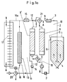
- in schematischer Darstellung eine erfindungsgemäße Trocknungsvorrichtung, bei der durch die eine,in einem Trocknungskreislauf liegende Trocknungspatrone mit Feuchtigkeit beladene Trocknungsluft geführt ist und bei der eine andere Patrone in einem Regenerierkreislauf getrocknet wird.
- Fig. 1b
- eine Darstellung entsprechend Fig.1a, wobei die eine Patrone in den Regenerierkreislauf und die andere Patrone in den Trocknungskreislauf geschaltet ist,
- Fig.2
- die Vorrichtung gemäß Fig.1a, bei der der Regenerierkreislauf zum Auslassen der zum Regenerieren verwendeten heißen Luft geöffnet ist,
- Fig.3
- die Vorrichtung gemäß Fig. 1a, bei der die eine getrocknete Patrone im Kreislauf gekühlt wird,
- Fig.4
- eine weitere Möglichkeit der Führung der Regenerierluft während der Rückkühlung, bei welcher nur ein Teilstrom der abzuführenden Energie in den Teilstrom über den Wärmetauscher geführt wird.
- Fig. 1a
- a schematic representation of a drying device according to the invention, in which the drying cartridge loaded with moisture is guided through the drying cartridge lying in a drying circuit and in which another cartridge is dried in a regeneration circuit.
- Fig. 1b
- a representation corresponding to Figure 1a, wherein one cartridge is connected to the regeneration circuit and the other cartridge in the drying circuit,
- Fig. 2
- 1a, in which the regeneration circuit is open to let out the hot air used for regeneration,
- Fig. 3
- 1a, in which the one dried cartridge is cooled in the circuit,
- Fig. 4
- a further possibility of guiding the regeneration air during recooling, in which only a partial flow of the energy to be dissipated is led into the partial flow via the heat exchanger.
Mit der Trockenvorrichtung wird in einem Trocknungsbehältnis 1 befindliches Gut, vorzugsweise Kunststoffgranulat oder -pulver, mittels trockener Luft, sogenannter Trocknungsluft, getrocknet. In das Trocknungsbehältnis 1 mündet eine Zuführleitung 2, in der eine Heizeinrichtung 3 liegt, mit der die in der Zuführleitung strömende Trocknungsluft ggf. erwärmt werden kann. Die Mündung 4 der Zuführleitung 2 liegt im Bereich des Bodens des Trocknungsbehältnisses, so daß die aus ihr austretende trockene Luft im Trocknungsbehältnis nach oben in Richtung der eingezeichneten Pfeile strömt. Im oberen Bereich des Trocknungsbehältnisses 1 befindet sich ein Auslaß 5, an den eine Rückführleitung 6 angeschlossen ist. In ihr befindet sich ein Filter 7, um in der aus dem Trocknungsbehältnis strömenden Trocknungsluft enthaltenen Staub und dgl. aufzufangen. In der Rückführleitung 6 befindet sich außerdem ein Gebläse 8, das zwischen demFilter 7 und einer Trocknungspatrone 9 liegt, in die die Rückführleitung 6 mündet. Die Zuführleitung 2 ist ebenfalls an die Trocknungspatrone 9 angeschlossen. Die Heizeinrichtung 3 befindet sich in Strömungsrichtung hinter der Trocknungspatrone, die vorzugsweise eine Molekularsieb-Patrone ist.With the drying device, material located in a drying
Im Trocknungsbehältnis 1 bfindet sich das zu trocknende Pulver oder Granulat. Die Trocknungsluft strömt über die Zuführleitung 2 in das Trocknungsbehältnis 1 und durchströmt das Granulat oder das Pulver . Hierbei nimmt die Trocknungsluft Feuchtigkeit aus dem Granulat oder Pulver auf und strömt über die Rückführleitung 6 und den Filter 7 in die Trocknungspatrone 9. Dort wird die von der Trocknungsluft aufgenommene Feuchtigkeit zurückgehalten, so daß wieder trockene Luft über die Zuführleitung 2 in das Trocknungsbehältnis 1 gelangt. Je nach gewünschter bzw. geforderter Trocknungstemperatur wird die Trocknungsluft in der Zuführleitung 2 mit der Heizeinrichtung 3 auf die erforderliche Temperatur erwärmt. Die Trocknungsluft wird somit in einem Trocknungskreislauf 10 geführt, wobei das Pulver oder das Granulat im gewünschten Maße getrocknet wird. In der Zeichnung ist nur eine Trocknungspatrone 9 im Trocknungskreislauf 10 dargestellt. Selbstverständlich ist es möglich, mehrere Trocknungspatronen 9 im Trocknungskreislauf 10 einzusetzen.The powder or granules to be dried are found in the drying
Die Trocknungsluft wird so lange im Kreislauf geführt, bis das Trocknungsgut im Behältnis 1 ausreichend entfeuchtet ist. Wenn die Trocknungspatrone 9 erschöpft ist und nur noch wenig Feuchtigkeit von der Trocknungsluft aufnehmen kann, wird sie regeneriert.The drying air is circulated until the material to be dried in the
Hierzu ist die Vorrichtung mit einem Regenerierkreislauf 11 versehen, in dem die zu regenerierende Patrone 9ʹ liegt. An sie ist eine Leitung 12 angeschlossen, die, was in Fig.1a nur anhand eines Leitungszweiges 16 schematisch dargestellt ist, von einer Isolierung 13 umgeben ist. Vorzugsweise sind sämtliche Leitungen gegenüber der Atmosphäre getrennt isoliert. In Strömungsrichtung der Regenerierluft hinter der zu regenerierenden Patrone 9ʹ liegt in der Leitung 12 ein Gebläse 14 und eine Heizeinrichtung 15. Sie liegt zwischen dem Gebläse 14 und der Patrone 9ʹ. Die Leitung 12 hat noch einen Leitungszweig 16a, in dem ein,vorzugsweise ebenfalls nach außen isolierter Wärmetauscher 17 liegt. Der Leitungszweig 16a kann über ein Ventil 18 geöffnet bzw. geschlossen werden. Bei der Darstellung gemäß Fig.1a ist der Leitungszweig 16a geschlossen, so daß die Regenerierluft im Regenerierkreislauf 11 in Richtung der eingezeichneten Pfeile strömt. Im Regenerierkreislauf 11 wird trockene Luft durch die Patrone 9ʹ geführt, wobei diese Luft die Feuchtigkeit aus der Patrone 9ʹ aufnimmt und sie somit trocknet. Das in der Patrone 9ʹ befindliche Wasser muß in Dampfform überführt werden. Deshalb wird die Regenerierluft mit der Heizeinrichtung 15 vor dem Eintritt in die Patrone 9ʹ so stark erhitzt (auf etwa 180°C bis 250°C), daß die Flüssigkeit in der Patrone 9ʹ in Dampfform überführt und somit von ihr aufgenommen werden kann. Die aus der Patrone 9ʹ austretende Luft hat sich infolge der Überführung der Flüssigkeit in die Dampfform abgekühlt, so daß die Heizeinrichtung 15 die Luft um diesen Abkühlungsbetrag vor dem Eintritt in die Patrone 9ʹ wieder aufheizt. Dieser Temperaturunterschied entspricht im wesentlichen nur der Verdampfungsenergie, die notwendig ist, um die Flüssigkeit in der Patrone 9ʹ in die Dampfform zu überführen. Da während des beschriebenen Trocknungsvorganges in den Regenerierkreislauf 11 keine atmosphärische Luft gelangt, kann die Patrone 9ʹ im Regenerierkreislauf 11 optimal entfeuchtet werden. Die Isolierung 13 stellt sicher, daß die Wärmeverluste beim Durchströmen der Leitung 12 gering sind, so daß die Heizeinrichtung 15 die Regenerierluft nur wenig aufheizen muß.Durch den geschlossenen Regenerierkreislauf 11 kann das in der Patrone 9ʹ befindliche Wasser praktisch ohne Energieverlust verdampft werden. Zwischen den Leitungen 6 und 12 ist in Strömungsrichtung der Trocknungsluft vor und in Strömungsrichtung der Regenerierluft hinter der Patrone 9 bzw. 9ʹ (Fig.1a) ein Ventil 19 eingebaut, das in Fig. 1a eine solche Lage hat, daß die Trocknungsluft in der Leitung 6 der Trocknungspatrone 9 und die Regenerierluft nach Verlassen der zu regenerierenden Patrone 9ʹ der Heizeinrichtung 15 über das Gebläse 14 zugeführt wird.For this purpose, the device is provided with a
Wenn die Patrone 9ʹ getrocknet ist oder wenn die im Regenerierkreislauf 11 strömende Luft gesättigt ist, wird die Leitung 12 kurzzeitig geöffnet, damit die inzwischen mit Feuchtigkeit beladene Regenerierluft aus dem Regenerierkreislauf 11 austreten kann. Hierzu ist in der Leitung 12 nach dem Gebläse 14 ein Auslaßventil 20 vorgesehen, das in diesem Falle geöffnet wird (Fig.2). Gleichzeitig mit dem Austreten der mit Feuchtigkeit beladenen Regenerierluft strömt atmosphärische neue Luft bei "X" in die Leitung 12, mit der dann nach Schließen des Auslaßventiles erneut getrocknet werden kann. Mit dieser neuen Luft kann nunmehr in der beschriebenen Weise die gleiche oder eine andere Trocknungspatrone 9ʹ getrocknet werden. Die atmosphärische Luft ist zwar geringfügig mit Feuchtigkeit beladen, jedoch ist der Anteil der Feuchtigkeit innerhalb des Regenerierkreislaufes 11 gering, weil während des Regeneriervorganges nicht fortwährend neue atmosphärische Luft hinzugefügt wird, sondern im geschlosssenen Kreislauf geführt wird. Während des Ausblasens der verbrauchten Regenerierluft und des Einziehens neuer atmosphärischer Luft bleibt der Leitungszweig 16 a weiterhin geschlosssen. (Fig.2)
Wenn die Patrone 9ʹ im Regenerierkreislauf 11 getrocknet ist, kann sie in der Regel nicht sofort in den Trocknungskreislauf 10 geschaltet werden, weil sie beim Regeneriervorgang durch die heiße Regenerierluft erwärmt worden ist. Die Patrone 9ʹ ist nach der Regeneration zu heiß, so daß sie gekühlt werden muß. Hierzu wird die Heizeinrichtung 15 im Regenerierkreislauf 11 abgeschaltet bzw. durch Umschalten des Ventiles 18 in den Leitungsteil 16 gelegt, der nicht von Kühlluft durchströmt wird (Fig. 3). Dies hat den Vorteil, daß der in der Heizeinrichtung 15 enthaltene Wärmeinhalt weitgehend erhalten bleibt. Außerdem wird der Leitungszweig 16a über die Ventile 20, 18 geöffnet, so daß die Regenerierluft in Richtung der Pfeile in Fig. 3 im Kreislauf durch den Wärmetauscher 17 geführt wird. Da die Regenerierluft nicht mehr erwärmt wird, kann sie beim Durchströmen der getrockneten Patrone 9ʹ Wärme aufnehmen und sie dadurch kühlen. Die aus der Patrone 9ʹ austretende, erwärmte Luft durchströmt den Wärmetauscher 17 und gibt dabei ihre Wärme an ihn ab. Auf diese Weise wird die Patrone 9ʹ nach dem Trocknen (Fig.1a und 2) auf die erforderliche Temperatur gekühlt. Diese optimale Rückkühltemperatur liegt bei der Temperatur, die die Trocknungspatrone im Trocknungskreislauf hat. Es soll also soweit zurückgekühlt werden, daß bei Beendigung des Rückkühlvorganges die beiden Patronen 9,9ʹ (im Regenerierkreislauf und im Trocknungskreislauf) die gleiche Temperatur aufweisen. Es ist wichtig, den Wärmetauscher 17 in jedem Falle einzusetzen, da dies die ökonomischste Methode ist, die beiden Patronen 9,9ʹ auf gleiche Temperatur zu bringen. Die in der heißen (regenerierten) Patrone 9ʹ vorhandene Energie kann damit vollständig genutzt werden und die Zielsetzung der optimalen Rückkühltemperatur wird zwangsweise ohne weiteren Aufwand erreicht. Damit diese Vorteile erreicht werden können, ohne daß die Temperatur im Trocknungskreis zu hoch steigt, muß anstelle eines Umschaltventiles im Regenerierkreislauf 11 für die Umschaltung von der Aufheizphase in die Rückkühlphase das Regelventil 18 eingesetzt werden. Im einfachsten Fall kann anstelle des Regelventiles 18 auch eine Umschaltklappe vorgesehen sein. Sie wird nach einer ersten Umschaltung auf den Wärmetauscher 17 immer dann geschlossen, wenn die Temperatur im Trocknungskreislauf 10 den gewünschten Sollwert übersteigt und wird umgeschaltet, sobald diese Temperatur wieder unterschritten ist. Da bei der Rückkühlung die Luft im Kreislauf geführt wird, d. h. nicht fortwährend atmosphärische, mit Feuchtigkeit beladene Luft hinzugefügt wird, wird die Patrone 9ʹ bei diesem Kühlvorgang nicht schon mit Feuchtigkeit beladen. Durch diese Verfahrensweise wird ein extrem tiefer Taupunkt erreicht, der in der Größenordnung von etwa -50°C bis -70°C liegt. Durch die beschriebene Regenerierung wird somit ein optimaler Wirkungsgrad der Vorrichtung erreicht. Wenn die Patrone 9ʹ auf die geforderte Temperatur gekühlt worden ist, kann sie in den Trocknungskreislauf 10 geschaltet werden (Fig 1b; nunmehr Patrone 9), so daß sie wiederum die in diesem Kreislauf geförderte Trocknungsluft nach dem Durchgang durch das zu trocknende Gut im Trocknungsbehältnis 1 in der beschriebenen Weise entfeuchten kann.When the cartridge 9ʹ has dried or when the air flowing in the
When the cartridge 9ʹ has dried in the
Die beschriebene Kühlung der regenerierten Patrone 9ʹ ist notwendig, wenn sie heißer ist als die Eintrittstemperatur der im Trocknungskreislauf 10 strömenden Luft beim Eintritt in die Trocknungspatrone 9. Der Wärmetauscher 17 ist ein an sich bekannter Luft-Luft-Tauscher. Die vom Wärmetauscher 17 abgegebene Abwärme bei der Kühlung kann zur Erwärmung der Luft im Trocknungskreislauf 10 oder auch für andere Verwendungszwecke herangezogen werden. Mit der Abwärme kann die Luft im Trocknungskreislauf 10 dann erwärmt werden, wenn sie eine bestimmte Mindesttemperatur hat, die z. B. bei etwa 70°C liegt. In diesem Falle kann die Luft im Trocknungskreislauf 10 ebenfalls durch den Wärmetauscher 17 geführt werden, wobei sie die von ihm abgegebene Wärme aufnimmt. Dadurch kann der Energieaufwand der Vorrichtung gering gehalten werden.The described cooling of the regenerated cartridge 9ʹ is necessary if it is hotter than the inlet temperature of the air flowing in the drying
Um die regenerierte Patrone 9ʹ wieder in den Trocknungskreislauf 10 zu schalten, werden in bekannter Weise das Ventil 19 und ein Ventil 21 verwendet, die in die Leitungen 6 und 12 eingebaut sind. Das Ventil 21 sitzt in Strömungsrichtung der Trocknungsluft hinter der Patrone 9 und in Strömungsrichtung der Regenerierluft vor der Patrone 9ʹ (Fig.1a). Anstelle der Ventile 19,21 und 18,20 können auch Klappen, Drehventile (Drehkarussell) und dergleichen verwendet werden.In order to switch the regenerated cartridge 9ʹ back into the drying
Die beschriebene Trocknung und Kühlung (Fig.1a,3) der Patrone 9ʹ im Regenerierkreislauf 11 wird parallel zum Trocknungsvorgang der Patrone 9 im Trocknungskreislauf 10 durchgeführt.The described drying and cooling (Fig.1a, 3) of the cartridge 9ʹ in the
Wenn die Vorrichtung wenigstens zwei Trocknungspatronen hat, ist ein kontinuierlicher Trocknungsprozeß möglich (Fig. 1a, 1b). Solange die eine Trocknungspatrone 9 im Trocknungskreislauf 10 liegt (Fig.1a) kann die andere Patrone 9ʹ im Regenerierkreislauf 11 regeneriert werden. Sobald die Trocknungspatrone 9 im Trocknungskreislauf 10 erschöpft ist, kann die im Regenerierkreislauf 11 regenerierte Patrone 9ʹ in den Trocknungskreislauf (nunmehr Patrone 9; Fig. 1b) und die erschöpfte Trocknungspatrone 9 (nunmehr Patrone 9'; Fig. 1b) in den Regenerierkreislauf 11 geschaltet werden. Im Trocknungskreislauf 10 können weitere Trocknungspatronen vorgesehen sein.If the device has at least two drying cartridges, a continuous drying process is possible (Fig. 1a, 1b). As long as one drying
Fig. 4 zeigt eine Möglichkeit, wie die an den Wärmetauscher 17 abgegebene Wärme zum Aufheizen der im Trocknungskreislauf 10 strömeneden Luft herangezogen werden kann. Nach dem Austritt aus der Trocknungspatrone 9 muß die Luft wieder auf die jeweilige Temperatur aufgeheizt werden. Um hierbei Energie einzusparen, wird die Trocknungsluft nicht wieder direkt über die Heizeinrichtung 3, sondern über den Wärmetauscher 17 geführt. Wie anhand von Fig. 3 beschrieben worden ist, nimmt der Wärmetauscher 17 die Wärme der zum Kühlen im Regenerierkreislauf 11 strömenden Luft auf. Diese Wärme wird von der Luft im Trocknungskreislauf 10 aufgenommen, die am Wärmetauscher 17 vorbeiströmt. Somit wird die Trocknungsluft nach dem Durchtritt durch die Trocknungspatrone 9 schon aufgeheizt, so daß sie mit der Heizeinrichtung 3 nur noch wenig aufgeheizt werden muß.FIG. 4 shows one possibility of how the heat given off to the
Die in der Patrone 9ʹ vorhandene Energie wird über den Wärmetauscher 17 auf den Trocknungskreislauf 10 so übertragen, daß das Ventil 18 den Regenerierkreislauf 11 so aufteilt, daß ein Teilstrom über den Wärmetauscher 17 im Leitungszweig 16a und ein anderer Teilstrom über den Leitungszweig 16 (bei ausgeschalteter Heizung 15) geführt wird. Der eine über dem Wärmetauscher 17 strömende Teilstrom soll nur so groß sein, daß die Temperatur auf den Trockungskreislauf 10 nicht den Sollwert (bei ausgeschalteter Heizung 3) übersteigt. Das Ventil 18 kann auch so geschaltet sein, daß es entsprechend dem Energiebedarf im Trocknungskreislauf 10 in kurzen Abständen den Regenerierkreislauf 11 über die Zweigleitung 16a bzw. 16 führt.The energy present in the cartridge 9 'is transferred via the
Wenn für das Gut im Trocknungsbehältnis 1 nur tiefe Trocknungstemperaturen verwendet werden dürfen, dann wird die aus dem Trocknungsbehältnis austretende Luft nicht mehr über den Wärmetauscher 17 geführt, sondern ausschließlich im Trocknungskreislauf 10 entsprechend Fig. 3. Andererseits kann in diesem Falle die im Regenerierkreislauf 11 sitzende Patrone 9ʹ nach dem Regenerieren (Fig. 1a und 2) nicht sofort in den Trocknungskreislauf 10 geschaltet werden, weil dann die Temperatur dieser Patrone 9ʹ noch zu hoch ist. Um die Kühlung der Patrone 9ʹ,wie anhand von Fig.3 erläutert, zu beschleunigen, kann mit dem Gebläse 14 im Regenerierkreislauf 11 die Kühlluft im Kreislauf gefördert werden, um durch eine erhöhte Strömungsgeschwindigkeit den Wärmeaustausch an die Umgebung oder für andere Verwendungszwecke am Wärmetauscher 17 zu beschleunigen und damit die Trocknungspatrone 9ʹ rasch abzukühlen.If only low drying temperatures may be used for the material in the drying
Claims (8)
- Method for regenerating a drying cartridge (9') laden with moisture, in which fresh atmospheric air is supplied to a regenerating circuit (11), in which the drying cartridge (9') is located, which air flows through the drying cartridge (9') with repeated heating in the closed circuit, thus absorbing the moisture, which air is then cooled in the closed circuit, characterized in that the regenerating air is blown out on reaching saturation or when the drying cartridge (9') is dry, in that fresh atmospheric air for further drying is again supplied to the closed circuit, if the drying cartridge (9') is not yet completely dry when the regenerating air reaches saturation, in that this process is repeated until the drying cartridge (9') is dry and in that the drying cartridge (9') is then cooled by new atmospheric air, which is guided in the closed regenerating circuit (11) with repeated cooling.
- Method according to Claim 1, characterized in that the cooling air is guided through at least one heat exchanger (17).
- Method according to Claim 2, characterized in that at the heat exchanger (17), the cooling air of the regenerating circuit (11) is guided past drying air of a drying circuit (10) with a further drying cartridge (9), the cooling air delivering the heat absorbed upon flowing through the drying cartridge (9') to be regenerated, to the drying air.
- Method according to Claim 3, characterized in that the drying cartridge (9') located in the regenerating circuit (11) is cooled by the cooling air substantially to the same temperature as the drying cartridge (9) located in the drying circuit (10).
- Dryer with a regenerating apparatus for carrying out the method according to Claim 1, with a drying circuit, in which a container (1) for the material to be dried and at least one drying cartridge (9) are located, respectively one drying cartridge (9') being able to be controlled by means of a control member (19, 21) in a closed regenerating circuit (11) separated from the drying circuit (10), which circuit comprises a valve (20) facilitating the entry of atmospheric air and an outlet valve (20) for the moist regenerating air and in which are located at least one heating device (15), a fan (14) and at least one heat exchanger (17) able to be switched on by way of a control member (18) for the cooling phase of the cartridge to be regenerated.
- Dryer according to Claim 5 or 6, characterized in that the heating device (15) is located in the flow direction of the regenerating air between the fan (14) and the drying cartridge (9') to be regenerated.
- Dryer according to one of Claims 5 to 7, characterized in that during the cooling process, the heating device (15) is located in a part of the line (16) of the regenerating circuit (11) able to be closed off by the control part (18).
- Dryer according to one of Claims 5 to 8, which comprises at least two drying cartridges (9; 9'), characterized in that the drying circuit (10) can be connected to the heat exchanger (17).
Priority Applications (1)
| Application Number | Priority Date | Filing Date | Title |
|---|---|---|---|
| AT87115942T ATE86514T1 (en) | 1986-11-05 | 1987-10-30 | METHOD OF REGENERATING A MOISTURE-LOADED DRYING CARTRIDGE, AND DRYER WITH REGENERATION DEVICE FOR CARRYING OUT SUCH PROCESS. |
Applications Claiming Priority (2)
| Application Number | Priority Date | Filing Date | Title |
|---|---|---|---|
| DE3637700 | 1986-11-05 | ||
| DE19863637700 DE3637700A1 (en) | 1986-11-05 | 1986-11-05 | METHOD FOR REGENERATING A DRYING CARTRIDGE LOADED WITH MOISTURE AND DEVICE FOR CARRYING OUT SUCH A METHOD |
Publications (3)
| Publication Number | Publication Date |
|---|---|
| EP0266684A2 EP0266684A2 (en) | 1988-05-11 |
| EP0266684A3 EP0266684A3 (en) | 1988-08-03 |
| EP0266684B1 true EP0266684B1 (en) | 1993-03-10 |
Family
ID=6313230
Family Applications (1)
| Application Number | Title | Priority Date | Filing Date |
|---|---|---|---|
| EP87115942A Expired - Lifetime EP0266684B1 (en) | 1986-11-05 | 1987-10-30 | Method and dryer comprising an apparatus for the regeneration of a drying cartridge impregnated with moisture |
Country Status (8)
| Country | Link |
|---|---|
| US (1) | US4858335A (en) |
| EP (1) | EP0266684B1 (en) |
| JP (1) | JPS63130119A (en) |
| AT (1) | ATE86514T1 (en) |
| BR (1) | BR8705926A (en) |
| CA (1) | CA1305926C (en) |
| DE (2) | DE3637700A1 (en) |
| DK (1) | DK567787A (en) |
Families Citing this family (19)
| Publication number | Priority date | Publication date | Assignee | Title |
|---|---|---|---|---|
| US5335426A (en) * | 1992-09-22 | 1994-08-09 | Foothills Medical Equipment, Inc. | Method and apparatus for thermal regeneration of molecular sieve material used in oxygen concentrators |
| DE4317768A1 (en) * | 1993-05-28 | 1994-12-01 | Somos Gmbh | Method and device for processing a particularly moist adsorbent |
| DE4344593C1 (en) * | 1993-12-24 | 1995-02-16 | Somos Gmbh | Apparatus for drying bulk material |
| US5485686A (en) * | 1994-05-25 | 1996-01-23 | Dri-Air Industries, Inc. | Hi-performance desiccant tower |
| DE19516311A1 (en) * | 1995-05-04 | 1996-11-07 | Graeff Roderich Wilhelm | Method and device for preparing an adsorbent containing an agent, in particular moisture |
| DE19531446A1 (en) * | 1995-08-26 | 1997-02-27 | Motan Holding Gmbh | Device with at least one storage container for material to be treated, preferably plastic granules |
| US5604991A (en) * | 1996-02-06 | 1997-02-25 | Westinghouse Air Brake Company | Switching and purging mechanism for a twin tower air dryer |
| DE59608068D1 (en) * | 1996-05-03 | 2001-12-06 | Graeff Roderich Wilhelm | Method and device for preparing an adsorbent |
| DE10118762A1 (en) * | 2001-04-08 | 2002-10-17 | Wittmann Robot Systeme Gmbh | Process for the regeneration of moisture-laden process air and arrangement for carrying out the process |
| ITPD20040038A1 (en) * | 2004-02-16 | 2004-05-16 | Plastic Systems Srl | DEHUMIDIFICATION PROCESS OF PLASTIC MATERIALS IN GRANULES AND PLANT OPERATING IN ACCORDANCE WITH SUCH PROCESS |
| DE102006049437B3 (en) * | 2006-10-16 | 2008-03-27 | Lanco Gmbh | Hot air drying equipment for bulk materials, especially plastic granules, includes valves controlling air flow recirculated between drying chamber and drying agent chamber |
| US8686355B2 (en) * | 2012-03-08 | 2014-04-01 | Morpho Detection, Llc | Detection system assembly, dryer cartridge, and regenerator and methods for making and using the same |
| US9452387B2 (en) | 2014-10-10 | 2016-09-27 | Meta Industrial Inc. | Dehumidifying apparatus |
| DE102015116331A1 (en) | 2015-09-28 | 2017-03-30 | Beko Technologies Gmbh | Cooling air utilization in the warmly regenerated forced air compressed air adsorption dryer |
| US10049868B2 (en) | 2016-12-06 | 2018-08-14 | Rapiscan Systems, Inc. | Apparatus for detecting constituents in a sample and method of using the same |
| CN110958914A (en) | 2017-08-10 | 2020-04-03 | 拉皮斯坎系统股份有限公司 | System and method for substance detection using a thermally stable collection device |
| WO2019147748A2 (en) | 2018-01-24 | 2019-08-01 | Rapiscan Systems, Inc. | Surface layer disruption and ionization utilizing an extreme ultraviolet radiation source |
| US11609214B2 (en) | 2019-07-31 | 2023-03-21 | Rapiscan Systems, Inc. | Systems and methods for improving detection accuracy in electronic trace detectors |
| CN115854667B (en) * | 2022-12-05 | 2024-03-12 | 深圳快造科技有限公司 | Drying cabinet and drying system |
Family Cites Families (9)
| Publication number | Priority date | Publication date | Assignee | Title |
|---|---|---|---|---|
| GB706045A (en) * | 1951-09-05 | 1954-03-24 | British Oxygen Co Ltd | Improvements in or relating to the drying of gases |
| DE2025205C3 (en) * | 1970-05-23 | 1984-09-20 | Gräff, Roderich W., Dr.-Ing., 6100 Darmstadt | Method and device for adsorbing water vapor from gases, preferably air |
| US4189848A (en) * | 1977-08-04 | 1980-02-26 | The United States Of America As Represented By The Department Of Energy | Energy-efficient regenerative liquid desiccant drying process |
| JPS5827480B2 (en) * | 1979-02-14 | 1983-06-09 | 株式会社日立製作所 | Dehumidification tower regeneration method for rare gas hold-up equipment |
| JPS5827480A (en) * | 1981-08-11 | 1983-02-18 | Sanyo Electric Co Ltd | Video level correction circuit for television receiver |
| JPS5888586A (en) * | 1981-11-24 | 1983-05-26 | 株式会社日立製作所 | Drier |
| DE3336048C2 (en) * | 1983-10-04 | 1985-08-29 | Klaus 8066 Bergkirchen Oschmann | Method and device for dehumidifying a drying gas |
| JPS60178009A (en) * | 1984-02-25 | 1985-09-12 | Color Toronitsuku Kk | Method and apparatus for generation of high temperature dehumidified air for drying synthetic resin |
| DE3412173A1 (en) * | 1984-03-31 | 1985-10-10 | Motan Gmbh, 7972 Isny | Process for regenerating adsorbents in adsorption units, especially molecular-sieve cartridges, of a drying appliance, and drying appliance for drying material held in a drying-material container |
-
1986
- 1986-11-05 DE DE19863637700 patent/DE3637700A1/en not_active Ceased
-
1987
- 1987-10-30 DE DE8787115942T patent/DE3784625D1/en not_active Expired - Fee Related
- 1987-10-30 AT AT87115942T patent/ATE86514T1/en not_active IP Right Cessation
- 1987-10-30 DK DK567787A patent/DK567787A/en not_active Application Discontinuation
- 1987-10-30 EP EP87115942A patent/EP0266684B1/en not_active Expired - Lifetime
- 1987-11-04 US US07/116,761 patent/US4858335A/en not_active Expired - Fee Related
- 1987-11-04 CA CA000550998A patent/CA1305926C/en not_active Expired - Fee Related
- 1987-11-04 BR BR8705926A patent/BR8705926A/en not_active IP Right Cessation
- 1987-11-04 JP JP62277536A patent/JPS63130119A/en active Pending
Also Published As
| Publication number | Publication date |
|---|---|
| CA1305926C (en) | 1992-08-04 |
| EP0266684A2 (en) | 1988-05-11 |
| DE3637700A1 (en) | 1988-05-19 |
| EP0266684A3 (en) | 1988-08-03 |
| DK567787A (en) | 1988-05-06 |
| ATE86514T1 (en) | 1993-03-15 |
| DK567787D0 (en) | 1987-10-30 |
| US4858335A (en) | 1989-08-22 |
| BR8705926A (en) | 1988-06-14 |
| JPS63130119A (en) | 1988-06-02 |
| DE3784625D1 (en) | 1993-04-15 |
Similar Documents
| Publication | Publication Date | Title |
|---|---|---|
| EP0266684B1 (en) | Method and dryer comprising an apparatus for the regeneration of a drying cartridge impregnated with moisture | |
| DE3005291A1 (en) | METHOD AND DEVICE FOR CONDITIONING AIR BY DRYING WITH A SORBENT MATERIAL | |
| EP0003964B1 (en) | Method and installation for recovering water from the atmosphere | |
| DE3112063C2 (en) | ||
| DE2707065C2 (en) | Method and device for the recovery of a liquid | |
| EP0740956A2 (en) | Process and apparatus for treatment of an adsorbent containing an agent, particularly moisture | |
| DE3814175A1 (en) | METHOD AND ARRANGEMENT FOR REGENERATING ADSORPTION MATERIAL | |
| DE3626887A1 (en) | Laundry machine and dishwasher, oven or the like, with a dehumidifier | |
| DE1176335B (en) | Method and device for regenerating a moisture exchanger for air conditioning systems | |
| EP0191835B1 (en) | Device for producing a flow of dry air | |
| DE10118762A1 (en) | Process for the regeneration of moisture-laden process air and arrangement for carrying out the process | |
| EP0595864A1 (en) | Paint spraying and drying booth. | |
| EP0805010B1 (en) | Process and apparatus for regenerating an adsorbent agent | |
| DE69210040T2 (en) | METHOD FOR REGENERATIVE HEAT EXCHANGE | |
| EP2921273B1 (en) | Method and device for drying polymeric granules | |
| WO1982000596A1 (en) | Device intended to dehumidify a drying gas medium using an adsorbant which is regenarated | |
| DE2610983A1 (en) | AIR CONDITIONING SYSTEM FOR THE TREATMENT OF FOOD | |
| DE2611084A1 (en) | DEVICE FOR THE REGENERATION OF A DRYING AGENT IN DRYERS FOR GASES AND AIR UNDER PRESSURE | |
| EP0103228A2 (en) | Device for reducing the solvent concentration in the tub of a dry-cleaning apparatus after the washing operation | |
| DE3637457C3 (en) | Device for deodorising textile fabrics treated with organic solvents and for recovering the solvents contained therein | |
| DE2363174B2 (en) | Device for drying and possibly smoking food | |
| DE3520046C2 (en) | ||
| DE69833507T2 (en) | METHOD AND SYSTEM FOR CONTROLLING THE AIRFLOW IN A DRYING SYSTEM WITH SEVERAL DRY BEDS | |
| DE60103327T2 (en) | Drying device and method for controlling the air flow in the device | |
| DE3123886C2 (en) | "Method and device for guiding the air to a mangle" |
Legal Events
| Date | Code | Title | Description |
|---|---|---|---|
| PUAI | Public reference made under article 153(3) epc to a published international application that has entered the european phase |
Free format text: ORIGINAL CODE: 0009012 |
|
| AK | Designated contracting states |
Kind code of ref document: A2 Designated state(s): AT BE CH DE ES FR GB IT LI LU NL SE |
|
| PUAL | Search report despatched |
Free format text: ORIGINAL CODE: 0009013 |
|
| AK | Designated contracting states |
Kind code of ref document: A3 Designated state(s): AT BE CH DE ES FR GB IT LI LU NL SE |
|
| 17P | Request for examination filed |
Effective date: 19890113 |
|
| 17Q | First examination report despatched |
Effective date: 19901210 |
|
| RAP1 | Party data changed (applicant data changed or rights of an application transferred) |
Owner name: MOTAN GMBH |
|
| RTI1 | Title (correction) | ||
| GRAA | (expected) grant |
Free format text: ORIGINAL CODE: 0009210 |
|
| AK | Designated contracting states |
Kind code of ref document: B1 Designated state(s): AT BE CH DE ES FR GB IT LI LU NL SE |
|
| PG25 | Lapsed in a contracting state [announced via postgrant information from national office to epo] |
Ref country code: SE Effective date: 19930310 Ref country code: NL Effective date: 19930310 Ref country code: BE Effective date: 19930310 |
|
| REF | Corresponds to: |
Ref document number: 86514 Country of ref document: AT Date of ref document: 19930315 Kind code of ref document: T |
|
| ET | Fr: translation filed | ||
| REF | Corresponds to: |
Ref document number: 3784625 Country of ref document: DE Date of ref document: 19930415 |
|
| ITF | It: translation for a ep patent filed | ||
| PG25 | Lapsed in a contracting state [announced via postgrant information from national office to epo] |
Ref country code: ES Free format text: LAPSE BECAUSE OF FAILURE TO SUBMIT A TRANSLATION OF THE DESCRIPTION OR TO PAY THE FEE WITHIN THE PRESCRIBED TIME-LIMIT Effective date: 19930621 |
|
| GBT | Gb: translation of ep patent filed (gb section 77(6)(a)/1977) |
Effective date: 19930615 |
|
| NLV1 | Nl: lapsed or annulled due to failure to fulfill the requirements of art. 29p and 29m of the patents act | ||
| PG25 | Lapsed in a contracting state [announced via postgrant information from national office to epo] |
Ref country code: AT Effective date: 19931030 |
|
| PG25 | Lapsed in a contracting state [announced via postgrant information from national office to epo] |
Ref country code: LU Free format text: LAPSE BECAUSE OF NON-PAYMENT OF DUE FEES Effective date: 19931031 |
|
| PLBE | No opposition filed within time limit |
Free format text: ORIGINAL CODE: 0009261 |
|
| STAA | Information on the status of an ep patent application or granted ep patent |
Free format text: STATUS: NO OPPOSITION FILED WITHIN TIME LIMIT |
|
| 26N | No opposition filed | ||
| PGFP | Annual fee paid to national office [announced via postgrant information from national office to epo] |
Ref country code: GB Payment date: 19960913 Year of fee payment: 10 |
|
| PGFP | Annual fee paid to national office [announced via postgrant information from national office to epo] |
Ref country code: FR Payment date: 19960918 Year of fee payment: 10 |
|
| PGFP | Annual fee paid to national office [announced via postgrant information from national office to epo] |
Ref country code: CH Payment date: 19961108 Year of fee payment: 10 |
|
| PGFP | Annual fee paid to national office [announced via postgrant information from national office to epo] |
Ref country code: DE Payment date: 19961217 Year of fee payment: 10 |
|
| PG25 | Lapsed in a contracting state [announced via postgrant information from national office to epo] |
Ref country code: GB Free format text: LAPSE BECAUSE OF NON-PAYMENT OF DUE FEES Effective date: 19971030 |
|
| PG25 | Lapsed in a contracting state [announced via postgrant information from national office to epo] |
Ref country code: LI Free format text: LAPSE BECAUSE OF NON-PAYMENT OF DUE FEES Effective date: 19971031 Ref country code: FR Free format text: THE PATENT HAS BEEN ANNULLED BY A DECISION OF A NATIONAL AUTHORITY Effective date: 19971031 Ref country code: CH Free format text: LAPSE BECAUSE OF NON-PAYMENT OF DUE FEES Effective date: 19971031 |
|
| REG | Reference to a national code |
Ref country code: CH Ref legal event code: PL |
|
| GBPC | Gb: european patent ceased through non-payment of renewal fee |
Effective date: 19971030 |
|
| PG25 | Lapsed in a contracting state [announced via postgrant information from national office to epo] |
Ref country code: DE Free format text: LAPSE BECAUSE OF NON-PAYMENT OF DUE FEES Effective date: 19980701 |
|
| REG | Reference to a national code |
Ref country code: FR Ref legal event code: ST |
|
| PG25 | Lapsed in a contracting state [announced via postgrant information from national office to epo] |
Ref country code: IT Free format text: LAPSE BECAUSE OF NON-PAYMENT OF DUE FEES;WARNING: LAPSES OF ITALIAN PATENTS WITH EFFECTIVE DATE BEFORE 2007 MAY HAVE OCCURRED AT ANY TIME BEFORE 2007. THE CORRECT EFFECTIVE DATE MAY BE DIFFERENT FROM THE ONE RECORDED. Effective date: 20051030 |