EP0266664A2 - Anordnung von einem Stopfbüchsengehäuse - Google Patents
Anordnung von einem Stopfbüchsengehäuse Download PDFInfo
- Publication number
- EP0266664A2 EP0266664A2 EP87115776A EP87115776A EP0266664A2 EP 0266664 A2 EP0266664 A2 EP 0266664A2 EP 87115776 A EP87115776 A EP 87115776A EP 87115776 A EP87115776 A EP 87115776A EP 0266664 A2 EP0266664 A2 EP 0266664A2
- Authority
- EP
- European Patent Office
- Prior art keywords
- gland
- packing
- gland packing
- holding member
- packing box
- Prior art date
- Legal status (The legal status is an assumption and is not a legal conclusion. Google has not performed a legal analysis and makes no representation as to the accuracy of the status listed.)
- Granted
Links
Images


Classifications
-
- F—MECHANICAL ENGINEERING; LIGHTING; HEATING; WEAPONS; BLASTING
- F04—POSITIVE - DISPLACEMENT MACHINES FOR LIQUIDS; PUMPS FOR LIQUIDS OR ELASTIC FLUIDS
- F04D—NON-POSITIVE-DISPLACEMENT PUMPS
- F04D29/00—Details, component parts, or accessories
- F04D29/08—Sealings
-
- F—MECHANICAL ENGINEERING; LIGHTING; HEATING; WEAPONS; BLASTING
- F16—ENGINEERING ELEMENTS AND UNITS; GENERAL MEASURES FOR PRODUCING AND MAINTAINING EFFECTIVE FUNCTIONING OF MACHINES OR INSTALLATIONS; THERMAL INSULATION IN GENERAL
- F16J—PISTONS; CYLINDERS; SEALINGS
- F16J15/00—Sealings
- F16J15/16—Sealings between relatively-moving surfaces
- F16J15/18—Sealings between relatively-moving surfaces with stuffing-boxes for elastic or plastic packings
- F16J15/182—Sealings between relatively-moving surfaces with stuffing-boxes for elastic or plastic packings with lubricating, cooling or draining means
-
- F—MECHANICAL ENGINEERING; LIGHTING; HEATING; WEAPONS; BLASTING
- F16—ENGINEERING ELEMENTS AND UNITS; GENERAL MEASURES FOR PRODUCING AND MAINTAINING EFFECTIVE FUNCTIONING OF MACHINES OR INSTALLATIONS; THERMAL INSULATION IN GENERAL
- F16J—PISTONS; CYLINDERS; SEALINGS
- F16J15/00—Sealings
- F16J15/16—Sealings between relatively-moving surfaces
- F16J15/162—Special parts or details relating to lubrication or cooling of the sealing itself
-
- F—MECHANICAL ENGINEERING; LIGHTING; HEATING; WEAPONS; BLASTING
- F16—ENGINEERING ELEMENTS AND UNITS; GENERAL MEASURES FOR PRODUCING AND MAINTAINING EFFECTIVE FUNCTIONING OF MACHINES OR INSTALLATIONS; THERMAL INSULATION IN GENERAL
- F16J—PISTONS; CYLINDERS; SEALINGS
- F16J15/00—Sealings
- F16J15/16—Sealings between relatively-moving surfaces
- F16J15/18—Sealings between relatively-moving surfaces with stuffing-boxes for elastic or plastic packings
- F16J15/24—Sealings between relatively-moving surfaces with stuffing-boxes for elastic or plastic packings with radially or tangentially compressed packing
Definitions
- This invention relates to a gland packing box composed in a shaft seal part of a hydraulic machine, and more particularly to a structure of a gland packing box suppressing the power loss as much as possible while enhancing the lubricating function and cooling function of the seal part.
- numeral 100 is a packing box formed at an end of, for example, a pump casing
- 101 is a neck bush
- 103A, 103B are gland packings
- 104 is a packing gland
- 105 is a rotary shaft, in which the gland packings 103A, 103B are pressed in the axial direction with a specified tightening pressure by the neck bush 101 inserted deep in the packing box 100 and the packing gland 104 with the end part set in the opening of packing box 100, thereby keeping a sealing performance to the rotary shaft 105.
- the structure of the gland packing box is so designed as to prevent abnormal wear of the rotary shaft 104 or seizure of seal part 106 due to dry operation, by allowing to escape slightly the fluid from the seal part 106 between the outside of the rotary shaft 105 and the inside of the gland packings 103A, 103B, and providing this escaping fluid with lubricating function and cooling function.
- the gland packing fitting faces 101A, 104A abutting against the gland packings 103A, 103B of the neck bush 101 and packing gland 104 are formed in a shape to be perpendicular and uniform to the axial line of the rotary shaft 105, and the gland packing 103A, 103B are held by these packing fitting faces 101A, 104A, so that the axial ends of the gland packings 103A, 103B naturally cross perpendicularly and uniformly to the axial line of the rotary shaft 105.
- a tiny annular gap 107 formed between the inside of neck bush 101 and outside of rotary shaft 105 only corresponds to the axial end of the gland packing 103A, and does not overlap with the inside of the gland packing 103A in the circumferential direction.
- the escaping fluid functioning as lubricant and coolant is sent into the seal part 106 only through the inner end in the axial direction of the tiny annular gap 107.
- the inside of the gland packings 103A, 103B and the outside of the rotary shaft 105 forming the seal part 106 is in tight contact state, and it is practically difficult to send the escaping fluid only by the fluid pressure in the casing into such seal part 106, and the leak flow is diminutively limited, and the lubricating function and cooling function cannot be exhibited effectively.
- cooling jacket 109 on the peripheral wall of the packing box 100, and, for example, cooling water is circulated, and a passage 110 communicating with the tiny annular gap 108 is formed in the packing gland 104, and through this passage 110, for example, cooling water is introudced into the tiny annular gap 108 to enhance the cooling effect.
- cooling jacket 109 since the cooling jacket 109 is only to cool the gland packings 103A, 103B directly, the cooling effect on the seal part 106 is not expected much, and the lubricating effect is not expected at all.
- This invention in the light of the above situations, is hence intended to present a structure of a gland packing box capable of preventing occurrence of abnormal wear of the rotary shaft, seizure of the seal part, or the like, and suppressing the power loss as much as possible, by sending a fluid into the seal part effectively to enhance the lubricating function and cooling function.
- gland packing box of this invention is that at least one dislocating part for partially dislocating the gland packing in the axial direction is formed on the fitting face of a gland packing holding member, by providing with the gland packing holding member for holding in the axial direction the packing box and the gland packing externally fitted on the rotary shaft in the packing box.
- the partially dislocated portion of the gland packing in the axial direction overlaps with the other inner surface of the partially dislocated gland packing in the circumferential direction, so that the escaping fluid is forced to be sent into the inside of the gland packing which is overlapped along with the rotation of the rotary shaft, and the lubricating performance and cooling performance on the inner surface of the gland packing are effective improved.
- gland packing box of this invention Another characteristic of the structure of gland packing box of this invention is that the entire fitting face of the gland packing holding member is formed at a same angle with respect to the axial direction of the holding member.
- one side of the gland packing abutting against the gland packing holding member is uniformly pressed over the entire peripheral direction, and when the dislocating portion for partially dislocating the gland packing in the axial direction is formed on the fitting face of the gland packing holding member, the shaft sealing performance is not disturbed.
- gland packing holding member is composed of a pair of neck bushes, and that of the neck bushes is disposed between the gland packing and the packing gland for fixing in the packing box.
- the structure may be easily applied to the existing packing box and packing gland.
- the most preferable embodiment to be applied to such existing product is to dispose an annular plate member having at least one dislocating portion for partially dislocating the gland packing in the axial direction between the gland packing and the gland packing holding member.
- the means for partially dislocating the gland packing in the axial direction is shaped like a plate, it does not require wide space, and it can be easily incorporated into an existing product. What is more, the dislocating portion is easy to fabricate and is inexpensive.
- Fig. 1 is a sectional view showing a first embodiment of the structure of gland packing box of this invention, in which numeral 1 denotes a packing box, being formed at one end of, for example, a pump casing.
- numeral 2 is a gland packing holding member, being composed of a neck bush 2A inserted deep in the packing box 1 and a packing gland 2B with its front end fitting into the opening in the packing box 1, and gland packings 3A, 3B are held in the axial direction by the gland packing holding member 2 in the packing box 2 and are externally fitted on a rotary shaft 4.
- one end of the gland packing 3A in the axial direction abuts against the fitting face 2A of the neck bush 2A, and the other end of the gland packing 3B in the axial direction abuts against the fitting face 2b of the packing gland 2B.
- a tightening function (not shown)
- the inside of the gland packings 3A, 3B are brought in tight contact with the outside of the rotary shaft 4, and a seal part 5 is formed by the inside of the gland packings 3A, 3B and the outside of the rotary shaft 4.
- dislocating parts 2ax, 2bx for dislocating the gland packings 3A, 3B in the axial direction are formed on the fitting faces 2a, 2b of the neck bush 2A and packing gland 2B for composing the gland packing holding member 2, dislocating parts 2ax, 2bx for dislocating the gland packings 3A, 3B in the axial direction are formed. That is, the dislocating part 2ax on the fitting face 2a in the neck bush 2A is a curved surface (see Fig. 2) moderately dislocating downward for the portion of the dimension t1 in the axial direction of the gland packing 3A with respect to each of the front and rear faces (only the rear face is shown in Fig.
- the dislocating part 2bx on the fitting face 2b in the packing gland 2B is a curved surface (see Fig. 2) moderately dislocating downward for the portion of the dimension t2 in the axial direction of the gland packing 2B with respect to each of the front and rear faces linking one side and the other side, similarly to said dislocating part 2ax.
- the tiny annular gap 6 formed between the inside of the neck bush 2A and the outside of the rotary shaft 4 overlaps with the region indicated by oblique line X in Fig. 2 on the inner surface of the gland packing 3A in the circumferential direction in the upper part of the left side in Fig. 1. Accordingly, the fluid in the gap 6 is forced to be sent as an escaping fluid into the region shown by said X along with the rotation of the rotary shaft 4, and from this region X, a large volume of the fluid uniformly distributes in the seal part 5, so that the lubricating function and cooling function are enhanced.
- the tiny annular gap 7 formed between the inside of the packing gland 2B and the outside of the rotary shaft 4 overlap with the region indicated by oblique line Y in Fig. 2 in the inner surface of the gland packing 2B in the circumferential direction in the lower part of the right side shown in Fig. 1. Therefore, the liquid escaping into the annular tiny gap 7 from the neck bush 2A side to the seal part 5 is forced ot be sent into the region indicated by Y along with the rotation of the rotary shaft 4, so that this part is effectively lubricated and cooled.
- Fig. 3 and Fig. 4 indicate a second embodiment of this invention, in which pairs of dislocating parts 2ax1, 2ax2, 2bx1, 2bx2 for deviating the gland packings 3A, 3B in the axial direction are formed on the fitting faces 2a, 2b of the neck bush 2A and packing gland 2B to compose the gland packing holding member 2. That is, the dislocating parts 2ax1, 2ax2 on the fitting face 2a at the neck bush 2A are curved surfaces partly dislocating downward for the portion corresponding to about half of the dimension t1 in the axial direction of the gland packing 3A from the vicinity of the middle part to the middle part of both front and rear faces (only rear face is shown in Fig.
- dislocating parts 2bx1, 2bx2 on the fitting face 2b at the packing gland 2B are curved surfaces dislocating downward for the portion corresponding to about half of the dimension t2 in the axial direction of the gland packing 3B from the vicinity of the middle part to the middle part of the front and rear faces of the fitting face 2b similarly to the dislocating parts 2ax1, 2ax2.
- the gland packings 2A, 2B are held by the fitting faces 2a, 2b of the gland packing holding member 2 composed of the neck bush 2A and packing gland 2B having dislocating parts 2ax1, 2ax2, 2bx1, 2bx2, it is dislocated in the axial direction by the portion corresponding to about half of the dimensions t1, t2 in the axial direction at the two front and rear positions on the circumference, and the tiny annular gap 6 in the neck bush 2A overlaps with the region indicated by oblique lines X1, X2 in Fig. 4 in the inner surface of the gland packing 3A in the circumferential direction in the upper part of the right and left sides in Fig. 3.
- the tiny annular gap 7 in the packing gland 2B overlaps with the region indicated by oblique lines Y1, Y2 in Fig. 4 in the inner surface of the gland packing 3B in the circumferential direction in the lower part of the right and left sides in Fig. 3.
- the fluid is forced to be sent into the region indicated by X1, X2 as a leaking fluid, and the fluid escaping to the lower part of the tiny annular gap 7 through the seal part 5 is forced to be sent into the region indicated by Y1, Y2, so that the lubricating function and cooling function are enhanced same as in the first embodiment.
- the lubricating function and cooling function is improved particularly in the middle part of the longitudinal direction of the seal part 5 by the fluid charged into the lantern ring 8, whereas the both ends of the seal part 5 in the longitudinal direction are effectively cooled and lubricated by disposing a coolant feed passage 9 communicating with the gap 6 inside the neck bush 2A and another coolant feed passage 10 communicating with the gap 7 in the packing gland 2B as indicated by virtual lines.
- Fig. 6 shows a fourth embodiment of this invention, in which gland packings 3A, 3B, 3C are held by the neck bush 2A1 inserted deep into the packing box 1 and the ring 2A2 inserted near the opening of the packing box 1, and dislocating parts 2a 1x , 2b 1x similar to, for example, those in the first embodiment are formed on the fitting faces 2a1, 2a2 of the neck bush 2A1, and ring 2A2, and the gland packings 3A, 3B, 3C are partially dislocated in the axial direction by the cooperation of the both dislocating parts 2a 1x , 2b 1x .
- the packing gland 2B since the upper surface of the ring 2A2 is formed flat, a conventional one having a flat holding surface may be used as the packing gland 2B.
- Fig. 7 denotes a fifth embodiment of this invention, in which a coil spring 11 is inserted between the neck bush 2A1 and the deep end of the packing box 1, and this spring force is always applied through the neck bush 2A1 to thrust the gland packings 3A, 3B, 3C in the axial direction.
- Fig. 9 represents a sixth embodiment of this invention, and is a sectional view for applying this invention into a device having a horizontal shaft (for example, a horizontal pump).
- a horizontal shaft for example, a horizontal pump
- This auxiliary seal 13 may be either the shown lip seal or a gland packing.
- Fig. 9 may be similarly applied when the embodiments shown in Fig. 3, Fig. 5, Fig. 6, Fig. 7 are used in horizontal shaft devices.
- Fig. 10 is a sectional view of essential parts to explain that the fitting faces 2a, 2a1, 2ax, 2b, 8a, 8b of the gland packing holding member 2 (composed of neck bushes 2A, 2A1, 2A2, packing gland 2B and lantern ring 8) are formed at an angle of 90 degrees with respect to the axial direction in the whole circumferential direction. That is, in this embodiment, by forming each fitting face at an angle of 90 degrees to the axial direction in the circumferential direction, the end faces of the gland packings 3A, 3B, 3C are pressed uniformly in the peripheral direction. That is, it is intended to prevent uneven sealing state in the peripheral direction due to uneven pressing of the end faces of the gland packings 3A, 3B, 3C in the peripheral direction.
- the gland packing holding member 2 is moved reciprocally in the horizontal direction while rotating in one direction by means of a milling machine, and one end of the gland packing holding member 2 is machined by the cutter 11, so that the entire circumference may be easily formed in an angle of 90 degrees.
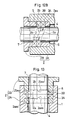
- Fig. 12A, Fig. 12B are sectional views of essential parts showing other modifications of the fitting faces.
- Fig. 12A is intended to increase the sealing force at the inner side of the gland packings 3A, 3B greater than the sealing force at the outer side by tapering the entire circumference of the fitting face 2b of the packing gland 2A in a same angle of ⁇ inward in the radial direction
- Fig. 12B is intended, to the contrary, to increase the sealing force at the outer side of the gland packings 3A, 3B greater than the sealing force at the inner side by tapering the entire circumference of the fitting face 2b of the packing gland 2B in a same angle ⁇ outward in the radial direction.
- Such tapering process of the entire circumference of the fitting face 2b in a same angle may be easily achieved by inclining the cutter 11 of the milling machine at a specified angle. Meanwhile, needless to say, this tapering of the fitting face may be applied not only to the packing gland 2B, but also to other gland packing holding member, such as fitting faces of the neck bush and lantern ring.
- Fig. 13 shows a seventh embodiment of this invention, in which fitting faces 2a, 2b of the neck bush 2A and packing gland 2B to compose the gland packing holding member 2 are formed in an angle of 90 degrees to the axial direction on the whole circumferential surface as shown also in Fig. 14, while plural (four in the drawing) projecting dislocating parts 2ax3 ..., 2bx3 ... for deviating the gland packings 3A, 3B inward in the axial direction are formed at specified intervals in the peripheral direction.
- the gland packings 3A, 3B are dislocated inward in the axial direction at four positions in the circumferential direction, and the tiny annular gap 6 formed between inside of the neck bush 2A and outside of rotary shaft 4 overlaps with the inner peripheral surface of the gland packing 3A not dislocated inward in the axial direction in the circumferential direction.
- the tiny gap 7 at the side of packing gland 2B also overlaps with the inner surface of the gland packing 3B not dislocated inward in the axial direction in the circumferential direction.
- the escaping fluid is forced to be sent into the inner surface of the gland packing 3A along with the rotation of the rotary shaft 24, while the fluid escaping into the lower part of the tiny annular gap 7 through the seal part 5 is forced to be sent into the inner surface of the gland packing 3B along with the rotation of the rotary shaft 24, so that the lubricating function and cooling function may be enhanced.
- Fig. 8a As the structure of gland packing box of shaft seal part of rotary shaft in a horizontal pump, the product of this invention shown in Fig. 8a and the conventional product shown in Fig. 8b were compared, and the results of measurements of fluid leak, gland part heating temperature and dynamic torque are shown in Table 1. Meanwhile, in Fig. 8a, X denote the distance of dislocation in the axial direction.
- test conditions were as follows:
- the displacement X was 4 mm.
- Fig. 15 shows an eighth embodiment of this invention, in which a gland packing holding member 2 ⁇ is composed of a neck bush 2 ⁇ A inserted deep in the packing box 1 and a packing gland 2 ⁇ B with its end fitted into the opening in the packing box 1, and gland packings 3A, 3B are externally mounted on a rotary shaft 4 as being held in the axial direction through plate-shaped members 12, 12 by means of the neck bush 2 ⁇ A and packing gland 2 ⁇ B.
- one end in the axial direction of the gland packing 3A abuts against the fitting face 12a of the plate-shaped member 12 disposed on the fitting face 2 ⁇ a of the neck bush 2 ⁇ A, while the other end in the axial direction of the gland packing 3B abuts against the fitting face 12a of the plate-shaped member 12 disposed on the fitting face 2 ⁇ b of the packing gland 2 ⁇ B.
- Said plate-shaped member 12 is made of a metal plate, and at its fitting face 12a side, as specifically shown in Fig. 2, plural (four in the embodiment) dislocating parts 12ax for dislocating the gland packings 3A, 3B in the axial direction are formed at specified intervals by press forming.
- gland packings 3A, 3B are held by the fitting faces 12a, 12a of a pair of plate-shaped members 12, 12 having said dislocated parts 12ax, they are partly dislocated in the axial direction by the portion of projection of the dislocating parts 12ax of the plate-shaped members 12.
- the tiny annular gap 6 formed between the inside of the neck bush 2 ⁇ A and the outside of the rotary shaft 4 is extended to the dislocated portion in the axial direction, and this portion of this extended gap 6 and the inner surface of the gland packing 3A not dislocated in the axial direction overlap with each other in the circumferential direction.
- the fluid in the gap 6 is forced to be sent into the inner surface of the gland packing 3A not dislocated in the axial direction along with the rotation of the rotary shaft 4, so that the lubricating function and cooling function are enhanced.
- the tiny annular gap 7 formed between the inside of the packing gland 2 ⁇ B and the outside of the rotary shaft 4 is extended to the portion partly dislocated in the axial direction of the gland packing 3B by the dislocating parts 12ax of the plate-shaped members 12, and this portion of extended gap 7 and the inner surface of the gland packing 3B not dislocated in the axial direction overlap with each other in the circumferential direction. Therefore, the fluid escaping into the tiny annular gap 7 from the neck bush 2 ⁇ A side through the seal part 5 is forced to be sent into the inner surface of the gland packing 3A not dislocated in the axial direction along with the rotation of the rotary shaft 4, so that this portion may be lubricated and cooled effectively.
- Fig. 17 shows a ninth embodiment of this invention, in which four gland packings 3A, 3B, 3C, 3D are used, and a lantern ring 8 ⁇ is placed between the gland packings 3B and 3C, and a gland packing holding member 2 ⁇ is composed of neck bush 2 ⁇ A, packing gland 2 ⁇ B and lantern ring 8 ⁇ , while plate-shaped members 12, 12, 12 are disposed on a fitting face 2 ⁇ b of the packing gland 2 ⁇ B and both fitting faces 8 ⁇ a, 8 ⁇ b of the lantern ring 8 ⁇ so as to partly dislocate in the axial direction of the gland packings 3B, 3C, 3D by means of their dislocating parts 12ax ).
- the sealed fluid charged into the lantern ring 8 ⁇ through the feed passage 13 is forced to be sent into the inner surface of the gland packings 3B, 3C, 3D not dislocated in the axial direction, and the lubricating function and cooling function may be effectively exhibited even if the overall length of the seal part 5 is long.
- Fig. 18 shows a tenth embodiment of this invention, in which a coil spring 11 is placed between a neck bush 2 ⁇ A and the deep end of the packing box 1, and its spring force is always applied to thrust the gland packings 3A, 3B, 3C in the axial direction through the neck bush 2 ⁇ A and plate-shaped member 12.
- Fig. 19 shows an eleventh embodiment of this invention, relating to a structure of a gland packing box for dislocating partly the gland packing in the axial direction by using a plate-shaped member 12, and this is a sectional view of application into a device having a horizontal shaft (for example, a horizontal pump).
- a horizontal shaft for example, a horizontal pump
- an auxiliary seal 13 is disposed same as in said Fig. 9.
- the auxiliary seal 13 is to be used here may be either the shown lip seal or a gland packing.
- This embodiemnt may be similarly applied to the case of using the embodiment shown in Fig. 17 or Fig. 18 into a horizontal shaft device.
- the lubricating function and cooling function of the seal part 5 are extremely enhanced by the dislocating parts 12ax ... of the plate-shaped member 12, and the power loss may be inhibited as much as possible by preventing abnormal wear of the rotary shaft or seizure of the seal part due to dry operation.
- the means for partly dislocating the gland packing in the axial direction is a plate-shaped member, it may be easily applied in a conventional structure of gland packing box, and furthermore since it is enough to form dislocating parts in the plate-shaped member, the manufacture is easy and the cost is low, and the practical effect is great.
Applications Claiming Priority (2)
| Application Number | Priority Date | Filing Date | Title |
|---|---|---|---|
| JP61266469A JPH0621663B2 (ja) | 1986-11-07 | 1986-11-07 | グランドパッキンボックスの構造 |
| JP266469/86 | 1986-11-07 |
Publications (3)
| Publication Number | Publication Date |
|---|---|
| EP0266664A2 true EP0266664A2 (de) | 1988-05-11 |
| EP0266664A3 EP0266664A3 (en) | 1989-02-01 |
| EP0266664B1 EP0266664B1 (de) | 1992-03-11 |
Family
ID=17431360
Family Applications (1)
| Application Number | Title | Priority Date | Filing Date |
|---|---|---|---|
| EP87115776A Expired - Lifetime EP0266664B1 (de) | 1986-11-07 | 1987-10-27 | Anordnung von einem Stopfbüchsengehäuse |
Country Status (5)
| Country | Link |
|---|---|
| US (1) | US4844479A (de) |
| EP (1) | EP0266664B1 (de) |
| JP (1) | JPH0621663B2 (de) |
| KR (1) | KR910005636B1 (de) |
| DE (1) | DE3777330D1 (de) |
Cited By (1)
| Publication number | Priority date | Publication date | Assignee | Title |
|---|---|---|---|---|
| EP0502445A2 (de) * | 1991-03-02 | 1992-09-09 | Fichtel & Sachs AG | Stossdämpfer |
Families Citing this family (10)
| Publication number | Priority date | Publication date | Assignee | Title |
|---|---|---|---|---|
| DE3886054T2 (de) * | 1988-01-12 | 1994-05-11 | Heliseal Pty Ltd | Schraubförmige dichtung. |
| JPH0781642B2 (ja) * | 1988-06-23 | 1995-09-06 | 日本ピラー工業株式会社 | グランドパッキン |
| US5577737A (en) * | 1993-09-02 | 1996-11-26 | Universal Stuffing Box, Inc. | Method and apparatus for establishing and maintaining a fluid seal around a polishing rod |
| JP2001330157A (ja) * | 2000-05-22 | 2001-11-30 | Shimazaki Seisakusho:Kk | 回転軸用セルフシール装置 |
| US6705953B2 (en) * | 2002-05-23 | 2004-03-16 | Michael A. Haskins | Viscous golf practice turf |
| CN102817570A (zh) * | 2011-09-30 | 2012-12-12 | 南通新诚电子有限公司 | 油田井口用盘根密封装置 |
| US20160047481A1 (en) * | 2014-08-14 | 2016-02-18 | Hyundai Motor Company | Air supply system valve |
| US10054130B1 (en) * | 2017-06-19 | 2018-08-21 | Dekalb Blower Inc. | Rotary seal for an industrial fan assembly |
| US11374458B2 (en) | 2018-10-24 | 2022-06-28 | Dekalb Blower Inc. | Electric motor with fluid cooling |
| US11255319B2 (en) * | 2019-03-09 | 2022-02-22 | Neo Mechanics Limited | Shaft-cylinder assembly for high temperature operation |
Citations (6)
| Publication number | Priority date | Publication date | Assignee | Title |
|---|---|---|---|---|
| FR739797A (fr) * | 1932-03-18 | 1933-01-17 | Garniture pour boîte d'étanchéité | |
| DE903878C (de) * | 1951-12-25 | 1954-02-11 | Iaweseria Ag | Stopfbuchsendichtung |
| FR1200245A (fr) * | 1958-03-06 | 1959-12-18 | Joint d'étanchéité autoserrant | |
| FR2103056A5 (de) * | 1970-07-29 | 1972-04-07 | Masch & Werkzeugbau Gmbh | |
| GB2139299A (en) * | 1983-04-26 | 1984-11-07 | Coal Ind | Improvements relating to seals |
| GB2166814A (en) * | 1984-11-07 | 1986-05-14 | Nl Industries Inc | Axially compressible rotary shaft seal |
Family Cites Families (10)
| Publication number | Priority date | Publication date | Assignee | Title |
|---|---|---|---|---|
| US1347351A (en) * | 1919-07-29 | 1920-07-20 | Murray Angus | Packing device for pistons, rams, rods, and the like |
| US1868199A (en) * | 1926-04-09 | 1932-07-19 | Pelterie Robert Esnault | Packing device |
| US2054369A (en) * | 1933-12-29 | 1936-09-15 | Baldwin Southwark Corp | Sealing means |
| US2394609A (en) * | 1944-02-14 | 1946-02-12 | Ethridge E Hardesty | Cable fitting |
| US2444211A (en) * | 1944-12-22 | 1948-06-29 | Wager Robert Hudson | Soot blower seal |
| US2667776A (en) * | 1950-10-31 | 1954-02-02 | Apex Electrical Mfg Co | Under liquid seal for rotatable shafts |
| FR1147802A (fr) * | 1956-04-19 | 1957-11-29 | Boutillon Ets | Garniture d'étanchéité pour arbre rotatif ou coulissant et joint comportant cette garniture |
| US3097855A (en) * | 1959-06-26 | 1963-07-16 | George H Allen | Sealing arrangement |
| US3157404A (en) * | 1962-03-19 | 1964-11-17 | Jabsco Pump Co | Shaft seal with corrugated frustoconical spring for driving or restraining sealing member |
| JPS5491659A (en) * | 1977-12-28 | 1979-07-20 | Furukawa Electric Co Ltd:The | Seal method of water cool type forces cooling cable terminal seal device |
-
1986
- 1986-11-07 JP JP61266469A patent/JPH0621663B2/ja not_active Expired - Fee Related
-
1987
- 1987-10-26 US US07/112,362 patent/US4844479A/en not_active Expired - Lifetime
- 1987-10-27 EP EP87115776A patent/EP0266664B1/de not_active Expired - Lifetime
- 1987-10-27 DE DE8787115776T patent/DE3777330D1/de not_active Expired - Fee Related
- 1987-11-07 KR KR1019870012597A patent/KR910005636B1/ko not_active IP Right Cessation
Patent Citations (6)
| Publication number | Priority date | Publication date | Assignee | Title |
|---|---|---|---|---|
| FR739797A (fr) * | 1932-03-18 | 1933-01-17 | Garniture pour boîte d'étanchéité | |
| DE903878C (de) * | 1951-12-25 | 1954-02-11 | Iaweseria Ag | Stopfbuchsendichtung |
| FR1200245A (fr) * | 1958-03-06 | 1959-12-18 | Joint d'étanchéité autoserrant | |
| FR2103056A5 (de) * | 1970-07-29 | 1972-04-07 | Masch & Werkzeugbau Gmbh | |
| GB2139299A (en) * | 1983-04-26 | 1984-11-07 | Coal Ind | Improvements relating to seals |
| GB2166814A (en) * | 1984-11-07 | 1986-05-14 | Nl Industries Inc | Axially compressible rotary shaft seal |
Cited By (3)
| Publication number | Priority date | Publication date | Assignee | Title |
|---|---|---|---|---|
| EP0502445A2 (de) * | 1991-03-02 | 1992-09-09 | Fichtel & Sachs AG | Stossdämpfer |
| EP0502445A3 (en) * | 1991-03-02 | 1992-10-28 | Fichtel & Sachs Ag | A container rod assembly |
| US5277284A (en) * | 1991-03-02 | 1994-01-11 | Fichtel & Sachs Ag | Container rod assembly |
Also Published As
| Publication number | Publication date |
|---|---|
| KR910005636B1 (ko) | 1991-08-01 |
| EP0266664B1 (de) | 1992-03-11 |
| JPH0621663B2 (ja) | 1994-03-23 |
| DE3777330D1 (de) | 1992-04-16 |
| US4844479A (en) | 1989-07-04 |
| KR880006468A (ko) | 1988-07-23 |
| JPS63120964A (ja) | 1988-05-25 |
| EP0266664A3 (en) | 1989-02-01 |
Similar Documents
| Publication | Publication Date | Title |
|---|---|---|
| US5048978A (en) | Squeeze film damper seal | |
| US4304409A (en) | Sealing assembly | |
| EP0731301B1 (de) | Dichtungsvorrichtung | |
| EP0207703B1 (de) | Dichtungsanordnung | |
| KR100266251B1 (ko) | 기계적 표면 밀봉수단 | |
| US6244599B1 (en) | Floating brush seal | |
| EP0441405B1 (de) | Wartungsleichte Hochleistungsspaltdichtung | |
| US5730447A (en) | Self-aligning magnetic rotary seal | |
| EP0266664A2 (de) | Anordnung von einem Stopfbüchsengehäuse | |
| KR970000341B1 (ko) | 스크류 로우터 머신 | |
| US5975538A (en) | Radial lip shaft seal | |
| GB2203203A (en) | Rotary joint assembly | |
| AU2009232214B2 (en) | Internally pressurised seals | |
| US4274298A (en) | Drive unit seal assembly | |
| JPH0465266B2 (de) | ||
| GB2253661A (en) | Shaft sealing assembly | |
| US4752077A (en) | Sliding ring seal | |
| CN1029422C (zh) | 高速高压液压旋转联接器 | |
| US6997461B2 (en) | High speed high pressure rotary | |
| US4265456A (en) | Sealing assembly | |
| GB2123100A (en) | Labyrinth seal | |
| US4427203A (en) | Sealing assembly for rotatable shafts | |
| EP0032433A1 (de) | Mittel zur Kühlung berührungsfreier Stirnringdichtungen | |
| JPH08166065A (ja) | 軸封装置 | |
| Floyd | Gas seals for rotating shafts |
Legal Events
| Date | Code | Title | Description |
|---|---|---|---|
| PUAI | Public reference made under article 153(3) epc to a published international application that has entered the european phase |
Free format text: ORIGINAL CODE: 0009012 |
|
| AK | Designated contracting states |
Kind code of ref document: A2 Designated state(s): DE FR GB IT |
|
| PUAL | Search report despatched |
Free format text: ORIGINAL CODE: 0009013 |
|
| AK | Designated contracting states |
Kind code of ref document: A3 Designated state(s): DE FR GB IT |
|
| 17P | Request for examination filed |
Effective date: 19890529 |
|
| 17Q | First examination report despatched |
Effective date: 19890821 |
|
| GRAA | (expected) grant |
Free format text: ORIGINAL CODE: 0009210 |
|
| AK | Designated contracting states |
Kind code of ref document: B1 Designated state(s): DE FR GB IT |
|
| ET | Fr: translation filed | ||
| REF | Corresponds to: |
Ref document number: 3777330 Country of ref document: DE Date of ref document: 19920416 |
|
| ITF | It: translation for a ep patent filed |
Owner name: SOCIETA' ITALIANA BREVETTI S.P.A. |
|
| PLBE | No opposition filed within time limit |
Free format text: ORIGINAL CODE: 0009261 |
|
| STAA | Information on the status of an ep patent application or granted ep patent |
Free format text: STATUS: NO OPPOSITION FILED WITHIN TIME LIMIT |
|
| 26N | No opposition filed | ||
| PGFP | Annual fee paid to national office [announced via postgrant information from national office to epo] |
Ref country code: GB Payment date: 20011008 Year of fee payment: 15 |
|
| PGFP | Annual fee paid to national office [announced via postgrant information from national office to epo] |
Ref country code: FR Payment date: 20011017 Year of fee payment: 15 |
|
| PGFP | Annual fee paid to national office [announced via postgrant information from national office to epo] |
Ref country code: DE Payment date: 20011128 Year of fee payment: 15 |
|
| REG | Reference to a national code |
Ref country code: GB Ref legal event code: IF02 |
|
| PG25 | Lapsed in a contracting state [announced via postgrant information from national office to epo] |
Ref country code: GB Free format text: LAPSE BECAUSE OF NON-PAYMENT OF DUE FEES Effective date: 20021027 |
|
| PG25 | Lapsed in a contracting state [announced via postgrant information from national office to epo] |
Ref country code: DE Free format text: LAPSE BECAUSE OF NON-PAYMENT OF DUE FEES Effective date: 20030501 |
|
| GBPC | Gb: european patent ceased through non-payment of renewal fee | ||
| PG25 | Lapsed in a contracting state [announced via postgrant information from national office to epo] |
Ref country code: FR Free format text: LAPSE BECAUSE OF NON-PAYMENT OF DUE FEES Effective date: 20030630 |
|
| REG | Reference to a national code |
Ref country code: FR Ref legal event code: ST |
|
| PG25 | Lapsed in a contracting state [announced via postgrant information from national office to epo] |
Ref country code: IT Free format text: LAPSE BECAUSE OF NON-PAYMENT OF DUE FEES Effective date: 20051027 |