EP0266651A2 - Covering for reservoirs filled with liquid - Google Patents
Covering for reservoirs filled with liquid Download PDFInfo
- Publication number
- EP0266651A2 EP0266651A2 EP87115667A EP87115667A EP0266651A2 EP 0266651 A2 EP0266651 A2 EP 0266651A2 EP 87115667 A EP87115667 A EP 87115667A EP 87115667 A EP87115667 A EP 87115667A EP 0266651 A2 EP0266651 A2 EP 0266651A2
- Authority
- EP
- European Patent Office
- Prior art keywords
- plates
- floating
- dome
- cover according
- cover
- Prior art date
- Legal status (The legal status is an assumption and is not a legal conclusion. Google has not performed a legal analysis and makes no representation as to the accuracy of the status listed.)
- Withdrawn
Links
Images


Classifications
-
- B—PERFORMING OPERATIONS; TRANSPORTING
- B65—CONVEYING; PACKING; STORING; HANDLING THIN OR FILAMENTARY MATERIAL
- B65D—CONTAINERS FOR STORAGE OR TRANSPORT OF ARTICLES OR MATERIALS, e.g. BAGS, BARRELS, BOTTLES, BOXES, CANS, CARTONS, CRATES, DRUMS, JARS, TANKS, HOPPERS, FORWARDING CONTAINERS; ACCESSORIES, CLOSURES, OR FITTINGS THEREFOR; PACKAGING ELEMENTS; PACKAGES
- B65D88/00—Large containers
- B65D88/34—Large containers having floating covers, e.g. floating roofs or blankets
- B65D88/36—Large containers having floating covers, e.g. floating roofs or blankets with relatively movable sections
Definitions
- the invention relates to a cover for pools filled with liquid, in particular from sewage treatment plants, consisting of a plurality of cover elements which are at least partially supported by floats.
- a cover for liquid-filled basins is known, which is composed of individual domed cover plates with a ring sector-like base.
- the cover is supported on the one hand in the area of the pump sump on an annular float surrounding the pump sump and on the other hand on rollers on a rail ring fastened to the circular basin crown.
- Known covers of this type have the disadvantage that they are always matched precisely to the basin diameter or the base area of the basin. As soon as a larger basin is to be covered, the cover must be redesigned, the individual cover elements each having to be made according to the base area of the basin.
- the invention is therefore based on the object to provide a cover for liquid-filled pools, in particular from sewage treatment plants, which can be adapted in a simple manner and without great effort to different pool sizes and pool shapes without complex molding costs, which is easy to assemble without a crane and where the usual requirements for the highest snow loads can be largely neglected.
- the cover elements consist of floating plates and dome plates, which are arranged across the board and alternately to one another and are releasably connected to one another.
- This training gives the possibility of placing the individual, light and easily transportable floating plates at a distance from one another in the liquid in the pool and connecting them to one another through the dome plates - these are dome-shaped plates - so that there is a full coverage.
- the low weight of this cover is also due to the fact that no special measures have to be taken to support the snow load. If the snow load is high, the cover will submerge slightly for a short time, and the snow can be thawed by the liquid that has a higher temperature.
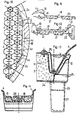
- the cover 1 shown only as a system in FIG. 1 consists of a plurality of floating plates 2, 3 and a plurality of coupling plates 4, which have the base of a regular hexagon or half a regular hexagon and are connected to one another in a manner that is not illustrated and explained further below.
- the floating plate 2 forms a so-called main float, around which dome plates 4 are connected at all six corners.
- Each floating plate 2 is made of glass fiber reinforced plastic as a relatively flat hollow body, which - as indicated in the present exemplary embodiment - is divided into six triangular hollow chambers. If necessary, the floating plate 2 can also be filled with foamed plastic (see FIG. 2).
- the floating plates 3 also consist of a hollow body made of glass fiber reinforced plastic, which, as indicated in FIG. 1, is divided into two chambers, for example, or, as can be seen in FIG. 3, is also filled with foam.
- a floating plate 5 is provided in the center between three floating plates 2 forming the corners of a triangle, which is formed either from six floating plates 3 or from three floating plates 2. If necessary, the floating plate 5 can also be formed in one piece. If necessary, two adjacent floating plates 3 can also be formed in one piece. It is advantageous to subdivide the floating plates 3, 5 into several smaller, if necessary, filled with synthetic resin foam chambers in order to ensure that, in the case of a leaky chamber, only an extremely small part of the floating plates 3, 5 impair the swimming function. The expansion of the chambers is min. 10 cm and max. about 40 cm.
- FIG. 1 of the drawing there are two lines 6 running parallel to each other over three coupling plates 4 arranged side by side. These lines 6 indicate that these three coupling plates 4 are either firmly connected to one another or are formed in one piece. It follows from this that a coupling element formed from three coupling plates 4 has three times the surface area as a floating plate 2. The same also applies to the floating plate 5.
- a cover 1 formed from floating plates 2, 3, 5 and dome plates 4 can be expanded to almost any size by adding individual floating plates 2, 3, 5 and dome plates 4 and thus adapted to the different sizes of the pools .
- 2 guide tubes 7 are inserted into the floating plates, which can accommodate support tubes, not shown, adjustable.
- each floating plate 5 can be provided with such guide tubes 7.
- Fig. 4 of the drawing the system of a cover 1a is shown, which is formed from cover elements with a triangular base.
- the base has an isosceles shape.
- the floating plates 3a have such a triangular base area and are provided in the drawing with a perpendicular bisector, which represents the subdivision of the floating plates 3a into two chambers, for example.
- the floating plates 2a have twice the base area as the floating plates 3a and have a Roman base area.
- the floating plates 2a, which are provided with a diagonal cross are preferably manufactured in one piece; however, they can also be composed of two floating plates 3a.
- the floating plates 2a, 3a are preferably formed from glass fiber reinforced plastic and are either hollow or filled with foamed plastic.
- the dome plates 4a also basically have the same base area as the floating plates 3a.
- several coupling plates 4a are combined to form a larger coupling plate.
- Dome plates 4a which are composed or formed in one piece are covered here either by two parallel lines 6 or by an elliptical line 8.
- 4 is now divided into four fields by dashed lines, in which different possible combinations or compositions of floating plates 2a, 3a and dome plates 4a are shown.
- Either four or six dome plates are combined to form a unit that forms either a Roman or a hexagonal base. Different covers 1a can be achieved by joining together such floating plates 2a and dome plates 4a.
- floating plates 2b with a square base are provided, which are connected to one another by dome plates 4b with a rectangular base.
- the dome plates 4b can have twice to five times the length of the floating plates 2b.
- the floating plates 2b of a row formed from floating plates 2b and dome plates 4b are arranged offset with respect to the floating plates 2b of the adjacent row.
- FIG. 6 shows the top view of a round basin 9, which can be supplemented with a corner 10 with a quadruple arrangement to form a square basin.
- the floating plates 2 basically have the area of a regular hexagon, while the dome plates 4 have the base of two hexagons and are therefore twice as large as the floating plates 2.
- the dome plates 4 change their direction in the individual sectors, which are characterized by floating plates 2 which are drawn more strongly. This alignment of the dome plates 4 thus results in six completely identical sectors, so that the edge connection of the cover 1, which will be discussed in more detail below, is reduced to six completely identical areas and can thus be considerably simplified.
- 7 now shows a floating plate 2 and a dome plate 4 formed from two hexagons, which thus has twice the base area as the floating plate 2.
- the floating plate 2 is provided with a circumferential projection 11 which in the exemplary embodiment shown has a trough-shaped cross section (FIG. 13).
- This groove-like projection 11 receives a correspondingly shaped side edge 12 of the dome plate 4.
- the dome plate 4 is made of two hexagonal domes 13 and has a sandwich-like reinforcement 14 in the transition area between the two domes 13, which is shaped like a staircase (FIGS. 8 and 9).
- FIG. 8 also shows in the right part that the side edges 15 of the coupling plate 4, to which a further coupling plate 4 is connected, have a sandwich-like reinforced flange 16 (FIG. 14).
- This step-like reinforcement 14 and the reinforced flange 16 give the possibility that there is a transition from each corner point of a floating plate 2 to the next floating plate 2. From Fig. 8 it can also be seen that the upper surface 17 of a floating plate 2 is convex. This design ensures that rainwater or the like can run to the edge of the floating plate 2 and thus into the channel-like projection 11.
- FIG. 10 shows the enlarged edge area of a sector of the cover 1 of FIG. 6.
- the edge area of such a cover 1 for a round basin is reduced to as few as possible closing parts 18 which can be connected to reduced coupling plates 4c or reduced floating plates 2c.
- the dome plates 4c (FIGS. 11 and 12) are provided with a bevel 19 which merges into a flange 16 or a side edge 12 in its lower region, as is the case with the normal dome plates 4.
- the end parts 18 are non-positively and / or positively connected to the coupling plates 4, 4c and the floating plates 2c. 11, the connecting part 18 consists of a relatively thin plate 20, which is reinforced by float 21 and is therefore designed to be walked on.
- the plate 20 is angled downward and immersed in the liquid in the basin as a so-called odor trap.
- the plate 20 of the connecting part 18 is designed as a sandwich composite element which either contains the additional floats 21 or is formed in one piece with the same.
- an angle piece 22 is connected here, which is also immersed as an odor trap in the liquid of the pool.
- a special edge profile 23 can be provided here, which protrudes above the pelvic crown and protects it from contamination or snow. This is important if the pelvic crown is used to hold a running rail for the drive wheels of a scraper bridge.
- FIG. 13 shows the edge of a floating plate 2 with a channel-like projection 11.
- several small spacers for example made of rubber, are placed on the bottom of the channel-like projection, on which then the side edge 12 of the dome plate 4 rests. This creates below the side edge 12 small channels 24, which allow, for example, the passage of rainwater or the like.
- the spacers made of rubber also ensure that no noise is generated, for example, when the wind is used.
- the side edges 12 of the dome plates 4 are held in their position in the channel-like projection 11 by means of a bracket 25.
- each floating plate 3 can, if necessary, be filled with water, for example rainwater, which only runs into the pool via the outer edge of the projection 11 when a predetermined liquid level is exceeded. This results in an optimal odor trap.
- the above-described connection between a floating plate 2 and a dome plate 4 also ensures that if the bottom of a basin is not excessively deformed, a cover 1 can be adapted to the floor without damage when it is covered.
- the floating plates 2 are provided at their corners with relatively short feet 26 which can accommodate supports 27. If necessary, these feet 26, as indicated in FIG. 1, can be designed as a guide tube in which a support tube which can be raised and lowered is arranged.
- Fig. 13 also shows the basic structure of a floating plate 2, which is formed as a hollow body made of glass fiber reinforced plastic and filled with foamed plastic.
- the floating plates 2 normally have a size of approximately 2 m and a height of approximately 16-20 cm.
- the dome plate 4 formed from two corner corners consequently has a length of almost 4 m.
- the floating plates 2 are dimensioned such that they carry not only their own weight, but also the snow load resting on them and the unloaded dome plates 4. Due to the higher temperature of the liquid, which is located below the cover, the snow falling on the relatively thin-walled dome plates 4 immediately thaws and runs down the channel-like projections 11 of the floating plates 2 into the pool. If, for some reason, this temperature of the liquid is no longer sufficient to thaw the snow over the coupling plates 4, this leads to the floating cover 1 being immersed in the liquid of the pool by a few centimeters. The liquid in the pool flows out through the channels 24 and defrosts the snow there with certainty.
- the snow on the floating plates 2 is also defrosted. After defrosting, melt water and pool water flow back into the pool via the channels 24 of the channel-like projections 11, so that the floating plates 2 and the dome plates 4 can assume their original position again. However, this presupposes that the outer edge of the channel-like projections 11 is arranged lower than the upper edge of the actual floating plate 2 (FIG. 13).
- This special design of the floating and dome plates 2.4 results in a particularly light and, in particular, inexpensive design of the cover, since it does not have to be dimensioned for carrying the snow load.
- the composite flanges 16 of the dome plates 4 are dimensioned so that these flanges 16 are able to carry the dome plate 4 in the water, so that the same can not go under.
- FIG. 15 shows a dome plate 4 corresponding to FIG. 9.
- the dome plate 4 is not formed as a continuous arch, but rather by flat surfaces.
- the floating plates 2d have a base area in the form of a ring sector and are combined with further floating plates 2d to form a ring. Dome plates 4d are placed between the individual rings of floating plates 2d, which also have a base area in the shape of a ring sector. If necessary, the outer coupling plates 4 can be supported on the pelvic crown 30 with their outer end via only indicated impellers 29.
- dome plates it is possible to take out individual rows of dome plates, so that the remaining parts can be lowered onto the supports even if the bottom of the basin is strongly inclined towards the center. Removing individual dome plates or rows of dome plates facilitates access for the operating personnel, for example for cleaning the basin and the underside of the remaining parts.
- the removed dome plates can be placed on the remaining dome and / or floating plates.
Landscapes
- Engineering & Computer Science (AREA)
- Mechanical Engineering (AREA)
- Bridges Or Land Bridges (AREA)
- Road Paving Structures (AREA)
Abstract
Description
Die Erfindung bezieht sich auf eine Abdeckung für mit Flüssigkeit gefüllte Becken, insbesondere von Kläranlagen, bestehend aus mehreren sich zumindest teilweise über Schwimmer abstützende Abdeckelemente.The invention relates to a cover for pools filled with liquid, in particular from sewage treatment plants, consisting of a plurality of cover elements which are at least partially supported by floats.
Aus der DE-OS 34 12 927 ist eine Abdeckung für flüssigkeitsgefüllte Becken bekannt, die aus einzelnen kuppelförmig gewölbten Abdeckplatten mit ringsektorartiger Grundfläche zusammengesetzt ist. Dabei stützt sich die Abdeckung einerseits im Bereich des Pumpensumpfes auf einem kreisringförmigen, den Pumpensumpf umgebenden Schwimmer und andererseits über Laufrollen auf einem auf der kreisförmigen Beckenkrone befestigten Schienenkranz ab. Derartige bekannte Abdeckungen haben den Nachteil, daß sie immer genau auf den Beckendurchmesser bzw. die Grundfläche des Beckens abgestimmt sind. Sobald ein größeres Becken abgedeckt werden soll, muß die Abdeckung neu konstruiert werden, wobei die einzelnen Abdeckelemente jeweils entsprechend der Grundfläche des Beckens angefertigt werden müssen. Dies ist nicht nur mit einem zusätzlichen konstruktiven Aufwand verbunden, sondern es müssen darüber hinaus auch für die Herstellung der Abdeckelemente für unterschiedlich große Becken neue Formen angefertigt werden, die bei einer anderen Beckengrundfläche normalerweise nicht mehr verwendbar sind. Insbesondere dann, wenn beispielsweise der Durchmesser von Rundbecken 20 m überschreitet, können durch Schnee so hohe Belastungen auftreten, daß eine Vielzahl von Laufrollen erforderlich ist, die den Rollwinderstand für eine Drehbewegung einer solchen Abdeckung in unerwünschter Weise erhöht. Andererseits muß der Querschnitt der einzelnen Abdeckelemente so vergrößert werden, daß dieselben ein hohes Gewicht aufweisen und nur noch einem Kran in ihre Montagestellung gebracht werden können. Darüber hinaus ist die Montage großflächiger Abdeckelemente aber auch umständlich und zeitraubend.From DE-OS 34 12 927 a cover for liquid-filled basins is known, which is composed of individual domed cover plates with a ring sector-like base. The cover is supported on the one hand in the area of the pump sump on an annular float surrounding the pump sump and on the other hand on rollers on a rail ring fastened to the circular basin crown. Known covers of this type have the disadvantage that they are always matched precisely to the basin diameter or the base area of the basin. As soon as a larger basin is to be covered, the cover must be redesigned, the individual cover elements each having to be made according to the base area of the basin. This is not only associated with additional design effort, but also new shapes must be made for the manufacture of the cover elements for pools of different sizes, which are normally no longer usable with another pool base. Especially when, for example, the diameter of round pools exceeds 20 m, snow can cause so High loads occur that a large number of rollers is required, which increases the rolling resistance for a rotary movement of such a cover in an undesirable manner. On the other hand, the cross section of the individual cover elements must be increased so that they have a high weight and can only be brought into their assembly position by a crane. In addition, the assembly of large-area cover elements is also cumbersome and time-consuming.
Der Erfindung liegt deshalb die Aufgabe zugrunde, eine Abdekkung für mit Flüssigkeit gefüllte Becken, insbesondere von Kläranlagen zu schaffen, die in einfachster Weise und ohne großen Aufwand unterschiedlichen Beckengrößen und Beckenformen ohne aufwendige Formkosten angepaßt werden kann, die leicht und ohne Kran zu montieren ist und bei der die bisher üblichen Anforderungen für höchste Schneelasten weitgehend vernachlässigt werden können.The invention is therefore based on the object to provide a cover for liquid-filled pools, in particular from sewage treatment plants, which can be adapted in a simple manner and without great effort to different pool sizes and pool shapes without complex molding costs, which is easy to assemble without a crane and where the usual requirements for the highest snow loads can be largely neglected.
Zur Lösung dieser Aufgabe wird gemäß der Erfindung bei einer Abdeckung der eingangs beschriebenen Gattung vorgeschlagen, daß die Abdeckelemente aus Schwimmplatten und Kuppelplatten bestehen, die flächendeckend und wechselweise zueinander angeordnet und lösbar miteinander verbunden sind. Diese Ausbildung gibt die Möglichkeit, die einzelnen, leichten und gut transportierbaren Schwimmplatten mit Abstand voneinander in die Flüssigkeit des Beckens zu setzen und durch die Kuppelplatten - das sind kuppelartig ausgebildete Platten - untereinander zu verbinden, so daß sich eine flächendeckende Abdeckung ergibt. Bei größeren Becken ist es lediglich erforderlich, einige Schwimmplatten und Kuppelplatten - ohne zusätzliche Formkosten - hinzuzufügen bzw. bei kleineren Becken wegzulassen. Das geringe Gewicht dieser Abdeckung kommt auch dadurch zustande, daß keine besonderen Maßnahmen zur Abstützung der Schneelast getroffen werden müssen. Bei hoher Schneelast taucht die Abdeckung kurzfristig geringfügig ein, und der Schnee kann durch die Flüssigkeit, die eine höhere Temperatur besitzt abtauen.To solve this problem it is proposed according to the invention in a cover of the type described above that the cover elements consist of floating plates and dome plates, which are arranged across the board and alternately to one another and are releasably connected to one another. This training gives the possibility of placing the individual, light and easily transportable floating plates at a distance from one another in the liquid in the pool and connecting them to one another through the dome plates - these are dome-shaped plates - so that there is a full coverage. For larger pools, it is only necessary to add some floating plates and dome plates - without additional molding costs - or to omit them for smaller pools. The low weight of this cover is also due to the fact that no special measures have to be taken to support the snow load. If the snow load is high, the cover will submerge slightly for a short time, and the snow can be thawed by the liquid that has a higher temperature.
Weitere Merkmale der Abdeckung gemäß der Erfindung sind in den Ansprüchen 2 - 19 offenbart.Further features of the cover according to the invention are disclosed in claims 2-19.
Die Erfindung wird nachfolgend anhand in einer Zeichnung dargestellter Ausführungsbeispiele näher erläutert. Dabei zeigen.
- Fig. 1 eine Draufsicht auf eine Abdeckung gemäß der Erfindung,
- Fig. 2 einen Schnitt durch die Abdeckung der Fig. 1 entlang der Linie A-A,
- Fig. 3 einen Schnitt durch die Abdeckung der Fig. 1 im rechten Winkel zur Schnittlinie A-A,
- Fig. 4 eine Draufsicht auf eine weitere Ausbildung einer Abdeckung,
- Fig. 5 eine Draufsicht auf eine weitere Abdecking gemäß der Erfindung,
- Fig. 6 eine der Fig. 1 entsprechende Abdeckung für ein Rund- bzw. Rechteckbecken,
- Fig. 7 eine Draufsicht auf eine Schwimmplatte und eine Doppel-Kuppelplatte,
- Fig. 8 einen Schnitt entlang der Linie B-B der Fig. 7,
- Fig. 9 einen vergrößerten Schnitt entlang der Linie C-C der Fig. 8,
- Fig. 10 eine vergrößerte Darstellung eines Ausschnittes der Abdeckung der Fig. 6,
- Fig. 11 einen vergrößerten Schnitt entlang der Linie E der Fig. 10,
- Fig. 12 eine andere Ausbildung des Randbereiches der Fig. 11,
- Fig. 13 einen Schnitt durch den Verbindungsbereich zwischen einer Schwimmplatte und einer Kuppelplatte,
- Fig. 14 eine Verbindung zwischen zwei Kuppelplatten,
- Fig. 15 eine der Fig. 9 entsprechende Darstellung einer Kuppelplatte,
- Fig. 16 eine ausschnittsweise Draufsicht auf eine weitere Ausbildung einer Abdeckung und
- Fig. 17 einen Schnitt durch die Abdeckung der Fig. 16.
- 1 is a plan view of a cover according to the invention,
- 2 shows a section through the cover of FIG. 1 along the line AA,
- 3 shows a section through the cover of FIG. 1 at right angles to the section line AA,
- 4 is a plan view of a further embodiment of a cover,
- 5 is a plan view of a further covering according to the invention,
- 6 a cover corresponding to FIG. 1 for a round or rectangular pool,
- 7 is a plan view of a floating plate and a double dome plate,
- 8 shows a section along the line BB of FIG. 7,
- 9 is an enlarged section along the line CC of FIG. 8,
- 10 is an enlarged view of a section of the cover of FIG. 6,
- 11 is an enlarged section along the line E of FIG. 10,
- 12 shows another embodiment of the edge region of FIG. 11,
- 13 shows a section through the connection area between a floating plate and a dome plate,
- 14 shows a connection between two coupling plates,
- 15 shows a representation of a coupling plate corresponding to FIG. 9,
- 16 is a partial plan view of a further embodiment of a cover and
- 17 shows a section through the cover of FIG. 16.
Die in der Fig. 1 nur als System dargestellte Abdeckung 1 besteht aus mehreren Schwimmplatten 2,3 und mehreren Kuppelplatten 4, die die Grundfläche eines regelmäßigen Sechsecks bzw. eines halben regelmäßigen Sechsecks aufweisen und in nicht dargestellter, weiter unten erläuterter Weise miteinander verbunden sind. Dabei bildet die Schwimmplatte 2 einen sogenannten Hauptschwimmer, um den an allen sechs Ecken Kuppelplatten 4 angeschlossen sind. Dabei ist jede Schwimmplatte 2 aus glasfaserverstärktem Kunststoff als verhältnismäßig flacher Hohlkörper ausgebildet, der entweder - wie im vorliegenden Ausführungsbeispiel angedeutet - in sechs dreieckförmige Hohlkammern unterteilt ist. Bedarfsweise kann die Schwimmplatte 2 auch mit aufgeschäumtem Kunststoff ausgefüllt sein (vgl. Fig. 2).The
Die Schwimmplatten 3 bestehen ebenfalls aus einem Hohlkörper aus glasfaserverstärktem Kunststoff, der entweder, wie in Fig. 1 angedeutet, beispielsweise in zwei Kammern unterteilt und oder, wie die Fig. 3 erkennen läßt, ebenfalls mit Schaumstoff gefüllt ist. Wie die Fig. 1 deutlich erkennen läßt, ist jeweils im Zentrum zwischen drei die Ecken eines Dreiecks bildenden Schwimmplatten 2 eine Schwimmplatte 5 vorgesehen, die entweder aus sechs Schwimmplatten 3 oder aus drei Schwimmplatten 2 gebildet ist. Bedarfsweise kann die Schwimmplatte 5 auch einstückig ausgebildet sein. Bedarfsweise können auch zwei benachbarte Schwimmplatten 3 einstückig ausgebildet sein. Es ist vorteilhaft, die Schwimmplatten 3,5 in mehrere kleinere, bedarfsweise mit Kunstharzschaum ausgefüllte Kammern zu unterteilen, um sicherzustellen, daß bei einer undichten Kammer nur ein äußerst kleiner Teil der Schwimmplatten 3,5 die Schwimmfunktion beeinträchtigt. Die Ausdehnung der Kammern beträgt min. 10 cm und max. etwa 40 cm.The
Die Fig. 2 und 3 der Zeichnung lassen erkennen, daß die Kuppelplatten 4 kuppelartig geformt sind. In der Fig. 1 der Zeichnung befinden sich über jeweils drei in Reihe nebeneinander angeordneten Kuppelplatten 4 zwei parallel zueinander verlaufende Linien 6. Diese Linien 6 sagen aus, daß diese drei Kuppelplatten 4 entweder fest miteinander verbunden oder einstückig augebildet sind. Daraus ergibt sich, daß ein aus drei Kuppelplatten 4 gebildetes Kuppelelement die dreifache Grundfläche wie eine Schwimmplatte 2 besitzt. Gleiches gilt auch für die Schwimmplatte 5. Eine aus Schwimmplatten 2,3,5 und Kuppelplatten 4 gebildete Abdeckung 1 kann durch Hinzufügen einzelner Schwimmplatten 2,3,5 und Kuppelplatten 4 auf annähernd jede beliebige Größe erweitert und damit den unterschiedlichen Größen der Becken angepaßt werden. Wie in Fig. 2 angedeutet, sind in die Schwimmplatten 2 Führungsrohre 7 eingesetzt, die nicht dargestellte Stützrohre einstellbar aufnehmen können. Zusätzlich kann auch jede Schwimmplatte 5 mit derartigen Führungsrohren 7 versehen sein.2 and 3 of the drawing show that the
In der Fig. 4 der Zeichnung ist das System einer Abdeckung 1a gezeigt, die aus Abdeckelementen mit dreieckiger Grundfläche gebildet ist. Die Grundfläche weist dabei eine gleichschenkelige Form auf. Die Schwimmplatten 3a besitzen eine solche dreieckige Grundfläche und sind in der Zeichnung mit einer Mittelsenkrechten versehen, die die Unterteilung der Schwimmplatten 3a beispielsweise in zwei Kammern darstellt. Die Schwimmplatten 2a weisen die doppelte Grundfläche wie die Schwimmplatten 3a auf und besitzen eine rombische Grundfläche. Dabei werden die Schwimmplatten 2a, die mit einem Diagonalkreuz versehen sind, vorzugsweise einstückig gefertigt; sie können jedoch auch aus zwei Schwimmplatten 3a zusammengesetzt sein. Die Schwimmplatten 2a, 3a sind vorzugsweise aus glasfaserverstärktem Kunststoff gebildet und entweder hohl geformt oder mit geschäumtem Kunststoff ausgefüllt. Auch die Kuppelplatten 4a weisen grundsätzlich die gleiche Grundfläche wie die Schwimmplatten 3a auf. Auch hier sind, in gleicher Weise wie in Fig. 1 jeweils mehrere Kuppelplatten 4a zu einer größeren Kuppelplatte zusammengefaßt. Zusammengesetzte bzw. einstückig ausgebildete Kuppelplatten 4a sind hier entweder von zwei parallelen Linien 6 oder einer elliptischen Linie 8 überdeckt. Die Fig. 4 ist durch strichlierte Linien nun in vier Felder unterteilt, in denen unterschiedliche Kombinationsmöglichkeiten bzw. Zusammensetzungen von Schwimmplatten 2a, 3a und Kuppelplatten 4a dargestellt sind. Dabei sind entweder vier oder sechs Kuppelplatten zu einer Einheit zusammengefaßt, die entweder eine rombische oder eine sechseckige Grundfläche bildet. Durch Aneinanderfügen derartiger Schwimmplatten 2a und Kuppelplatten 4a lassen sich unterschiedliche Abdeckungen 1a erzielen.In Fig. 4 of the drawing, the system of a cover 1a is shown, which is formed from cover elements with a triangular base. The base has an isosceles shape. The floating
Bei dem Ausführungsbeispiel der Fig. 5 sind Schwimmplatten 2b mit quadratischer Grundfläche vorgesehen, die durch Kuppelplatten 4b mit rechteckiger Grundfläche miteinander verbunden sind. Die Kuppelplatten 4b können dabei die doppelte bis fünffache Länge der Schwimmplatten 2b aufweisen. Die Schwimmplatten 2b einer aus Schwimmplatten 2b und Kuppelplatten 4b gebildeten Reihe sind gegenüber den Schwimmplatten 2b der benachbarten Reihe versetzt angeordnet.In the embodiment of FIG. 5, floating
In der Fig. 6 ist die Draufsicht auf ein Rundbecken 9 gezeigt, welches mit einer Ecke 10 mit vierfacher Anordnung zu einem quadratischen Becken ergänzt werden kann. Die Schwimmplatten 2 weisen hier grundsätzlich die Fläche eines regelmäßigen Sechsecks auf, während die Kuppelplatten 4 die Grundfläche von zwei Sechsecken besitzen und somit doppelt so groß wie die Schwimmplatten 2 ausgebildet sind. In dieser Darstellung ist besonders deutlich zu erkennen, daß die Kuppelplatten 4 in den einzelnen Sektoren, die durch verstärkt gezeichnete Schwimmplatten 2 gekennzeichnet sind, ihre Richtung ändern. Diese Ausrichtung der Kuppelplatten 4 ergibt somit sechs vollkommen gleiche Sektoren, so daß der Randanschluß der Abdeckung 1, auf den weiter unten näher eingegangen wird, auf sechs vollkommen gleiche Bereiche reduziert und damit erheblich vereinfacht werden kann. Die Fig. 7 zeigt nun eine Schwimmplatte 2 und eine aus zwei Sechsecken gebildete Kuppelplatte 4, die damit die doppelte Grundfläche wie die Schwimmplatte 2 aufweist. Dabei ist die Schwimmplatte 2 mit einem umlaufenden Vorsprung 11 versehen, der im dargestellten Ausführungsbeispiel rinnenförmigen Querschnitt aufweist (Fig. 13). Dieser rinnenartige Vorsprung 11 nimmt eine dementsprechend geformte Seitenkante 12 der Kuppelplatte 4 auf. Die Kuppelplatte 4 ist aus zwei sechseckigen Kuppeln 13 gefertigt, und weist im Übergangsbereich zwischen den beiden Kuppeln 13 eine sandwichartige Verstärkung 14 auf, die treppenartig geformt ist (Fig. 8 und 9). Die Fig. 8 läßt im rechten Teil auch erkennen, daß die Seitenkanten 15 der Kuppelplatte 4,an denen eine weitere Kuppelplatte 4 angeschlossen ist, einen sandwichartig verstärkten Flansch 16 besitzen (Fig. 14). Diese treppenartige Verstärkung 14 und der verstärkte Flansch 16 geben die Möglichkeit, daß von jedem Eckpunkt einer Schwimmplatte 2 ein Übergang zur nächsten Schwimmplatte 2 vorhanden ist. Aus der Fig. 8 ist ferner zu erkennen, daß die obere Fläche 17 einer Schwimmplatte 2 konvex ausgebildet ist. Diese Ausbildung stellt sicher, daß Regenwasser oder dgl. zum Rand der Schwimmplatte 2 und damit in den rinnenartigen Vorsprung 11 ablaufen kann.6 shows the top view of a
Die Fig. 10 zeigt den vergrößerten Randbereich eines Sektors der Abdeckung 1 der Fig. 6. Der Randbereich einer solchen Abdeckung 1 für ein rundes Becken wird auf möglichst wenige An schlußteile 18 zurückgeführt, die an verkleinerte Kuppelplatten 4c bzw. verkleinerte Schwimmplatten 2c anschließbar sind. Dazu werden die Kuppelplatten 4c (Fig. 11 und 12) mit einer Abschrägung 19 versehen, die in ihrem unteren Bereich in einen Flansch 16 bzw. eine Seitenkante 12 übergeht, wie dies bei den normalen Kuppelplatten 4 der Fall ist. Dabei werden die Abschlußteile 18 kraft- und/oder formschlüssig mit den Kuppelplatten 4, 4c bzw. den Schwimmplatten 2c verbunden. Gemäß der Fig. 11 besteht das Anschlußteil 18 aus einer verhältnismäßig dünnen Platte 20, die durch Schwimmer 21 verstärkt und damit begehbar ausgebildet ist. Am äußeren Rand des Anschlußteiles 18 ist die Platte 20 nach unten abgewinkelt und taucht in die Flüssigkeit des Beckens als sogenannter Geruchverschluß ein.FIG. 10 shows the enlarged edge area of a sector of the
Bei der Ausbildung gemäß Fig. 12 ist die Platte 20 des Anschlußteiles 18 als Sandwich-Verbundelement ausgebildet, welches entweder die zusätzlichen Schwimmer 21 enthält oder einstückig mit denselben geformt ist. Am äußeren Rand der Platte 20 ist hier ein Winkelstück 22 angeschlossen, welches ebenfalls als Geruchverschluß in die Flüssigkeit des Beckens eintaucht. Zusätzlich kann hier noch ein besonderes Randprofil 23 vorgesehen werden, welches über die Beckenkrone ragt und dieselbe vor Verunreinigungen oder Schnee schützt. Dies ist dann von Bedeutung, wenn die Beckenkrone zur Aufnahme einer Laufschiene für die Antriebsräder einer Räumerbrücke dient.In the embodiment according to FIG. 12, the
Wie bereits erwähnt, zeigt die Fig. 13 den Rand einer Schwimmplatte 2 mit einem rinnenartigen Vorsprung 11. Vor dem Einsetzen der Seitenkante 12 der Kuppelplatte 4 werden auf den Boden des rinnenartigen Vorsprunges 11 mehrere kleine Distanzstücke, beispielsweise aus Gummi, gelegt, auf denen dann die Seitenkante 12 der Kuppelplatte 4 aufliegt. Dadurch entstehen unterhalb der Seitenkante 12 kleine Kanäle 24, die beispielsweise den Durchgang von Regenwasser oder dgl. ermöglichen. Die aus Gummi bestehenden Distanzstücke stellen darüber hinaus sicher, daß beispielsweise bei einer Windbeanspruchung keine Geräusche entstehen. Mittels eines Bügels 25 werden die Seitenkanten 12 der Kuppelplatten 4 in ihrer Stellung im rinnenartigen Vorsprung 11 gehalten.As already mentioned, FIG. 13 shows the edge of a floating
Der rinnenartige Vorsprung 11 jeder Schwimmplatte 3 kann bedarfsweise mit Wasser, beispielsweise Regenwasser gefüllt sein, welches erst bei Überschreitung eines vorgegebenen Flüssigkeitsspiegels über die äußere Kante des Vorsprunges 11 in das Becken läuft. Dies ergibt einen optimalen Geruchverschluß. Die vorbeschriebene Verbindung zwischen einer Schwimmplatte 2 und einer Kuppelplatte 4 stellt darüber hinaus sicher, daß bei einem nicht zu extrem verformten Boden eines Beckens beim Abseken einer Abdeckung 1 einer beschädigungsfreie Anpassung derselben an den Boden möglich ist. Um zu erreichen, daß die Abdeckung 1 nicht direkt auf dem Boden aufliegt - eine Reinigung des Beckens wäre dann nicht möglich - sind die Schwimmplatten 2 an ihren Ecken mit verhältnismäßig kurzen Füßen 26 versehen, die Stützen 27 aufnehmen können. Bedarfsweise können diese Füße 26, wie in Fig. 1 angedeutet, als Führungsrohr ausgebildet sein, in dem ein heb- und senkbares Stützrohr angeordnet ist. Die Fig. 13 läßt auch den grundsätzlichen Aufbau einer Schwimmplatte 2 erkennen, die als Hohlkörper aus glasfaserverstärktem Kunststoff gebildet und mit geschäumtem Kunststoff ausgefüllt ist.The channel-
Die Fig. 14 zeigt die Flansche zweier benachbarter Kuppelplatten 4, die mittels mehrerer Schrauben 28 fest miteinander verbunden sind. Falls die Abdeckung 1 geruchsdicht sein muß, ist zwischen den beiden Flanschen 16 eine Dichtung angeordnet.14 shows the flanges of two
Die Schwimmplatten 2 haben normalerweise eine Größe von etwa 2 m und eine Höhe von etwa 16 - 20 cm. Die aus zwei Secksecken gebildete Kuppelplatte 4 weist demzufolge eine Länge von knapp 4 m auf. Dabei sind die Schwimmplatten 2 so dimensioniert, daß sie nicht nur ihr Eigengewicht, sondern auch die auf ihnen ruhende Schneelast sowie die unbelasteten Kuppelplatten 4 tragen. Durch die höhere Temperatur der Flüssigkeit, die sich unterhalb der Abdeckung befindet, taut der auf die verhältnismäßig dünnwandigen Kuppelplatten 4 fallende Schnee sofort auf und läuft über die rinnenartigen Vorsprünge 11 der Schwimmplatten 2 in das Becken ab. Sollte nun, aus irgendwelchen Gründen, diese Temperatur der Flüssigkeit nicht mehr zum Auftauen des Schnees über den Kuppelplatten 4 ausreichen, führt dies dazu, daß die schwimmende Abdeckung 1 um wenige Zentimeter in die Flüssigkeit des Beckens eintaucht. Dabei strömt die im Becken befindliche Flüssigkeit über die Kanäle 24 nach außen und taut dort mit Sicherheit den Schnee ab.The floating
Dabei wird auch der auf den Schwimmplatten 2 befindliche Schnee abgetaut. Nach dem Abtauen fließen Schmelzwasser und Beckenwasser wieder über die Kanäle 24 der rinnenartigen Vorsprünge 11 in das Becken zurück, so daß die Schwimmplatten 2 und die Kuppelplatten 4 wieder ihre ursprüngliche Lage einnenhmen können. Dies setzt jedoch voraus, daß die äußere Kante der rinnenartigen Vorsprünge 11 tiefer angeordnet ist als die Oberkante der eigentlichen Schwimmplatte 2 (Fig. 13). Diese besondere Ausbildung der Schwimm- und Kuppelplatten 2,4 ergibt eine besonders leichte und insbesondere preiswerte Ausbildung der Abdeckung, da diese nicht für ein Tragen der Schneelast dimensioniert werden muß. Die in Verbundbauweise ausgebildeten Flansche 16 der Kuppelplatten 4 sind so dimensioniert, daß diese Flansche 16 in der Lage sind, die Kuppelplatte 4 im Wasser zu tragen, so daß dieselbe nicht untergehen kann. Dies wirkt sich vorteil haft bei der Montage der Abdeckung 1 aus. Bei dieser Montage werden zuerst die Schwimmplatten 2 auf die Flüssigkeit des Beckens aufgesetzt und beispielsweise durch dünne Seile im vorgegebenen Abstand miteinander verbunden. Danach werden dann die Kuppelplatten 4 aufgesetzt und die Bügel 25 angeschraubt. Das Gewicht der Schwimmplatten 2 und der Kuppelplatten 4 beträgt nur jeweils etwa 50 - 60 kg, so daß eine Montage ohne Kran, also von Hand erfolgen kann.The snow on the floating
Die Fig. 15 zeigt eine der Fig. 9 entsprechende Kuppelplatte 4. Hier ist die Kuppelplatte 4 jedoch nicht als durchgehende Wölbung, sondern durch ebene Flächen gebildet.FIG. 15 shows a
Bei dem Ausführungsbeispiel der Fig. 16 und 17 weisen die Schwimmplatten 2d eine ringsektorförmige Grundfläche auf und sind mit weiteren Schwimmplatten 2d zu einem Ring zusammengesetzt. Zwischen den einzelnen Ringen aus Schwimmplatten 2d sind Kuppelplatten 4d aufgesetzt, die ebenfalls eine ringsektorförmige Grundfläche besitzen. Bedarfsweise können sich die äußeren Kuppelplatten 4 mit ihrem äußeren Ende über nur angedeutete Laufräder 29 auf der Beckenkrone 30 abstützen.In the embodiment of FIGS. 16 and 17, the floating
Beispielsweise bei dem Ausführungsbeispiel der Fig. 6 ist es möglich, einzelne Reihen von Kuppelplatten herauszunehmen, so daß die verbleibenden Teile auch dann auf die Stützen abgesenkt werden können, wenn der Boden des Beckens zum Mittelpunkt stark geneigt ist. Das Herausnehmen einzelner Kuppelplatten bzw. Reihen von Kuppelplatten erleichtert den Zugang für das Bedienungspersonal, beispielsweise zur Reinigung des Beckens und der Unterseite der verbleibenden Teile. Die entfernten Kuppelplatten können dabei auf den verbleibenden Kuppel- und/oder Schwimmplatten abgesetzt werden.For example, in the embodiment of FIG. 6, it is possible to take out individual rows of dome plates, so that the remaining parts can be lowered onto the supports even if the bottom of the basin is strongly inclined towards the center. Removing individual dome plates or rows of dome plates facilitates access for the operating personnel, for example for cleaning the basin and the underside of the remaining parts. The removed dome plates can be placed on the remaining dome and / or floating plates.
Ferner ist es möglich, aus preiswertem Werkstoff gebildete Kunststoffschaumblöcke zuzuschneiden und mit einem Spalt in die Kammer der Schwimmplatten einzulegen. Der verbleibende Spalt wird dann mit hochwertigerem Werkstoff ausgeschäumt.Furthermore, it is possible to cut plastic foam blocks formed from inexpensive material and insert them into the chamber of the floating plates with a gap. The remaining gap is then filled with higher quality material.
Claims (19)
dadurch gekennzeichnet,
daß die Abdeckelemente aus Schwimmplatten (2,2a,2b,2c,2d,3) und Kuppelplatten (4,4a,4b,4c,4d) bestehen, die flächendeckend und wechselweise zueinander angeordnet und lösbar miteinander verbunden sind.1. cover for pools filled with liquid, in particular from sewage treatment plants, consisting of a plurality of cover elements which are at least partially supported by floats,
characterized,
that the cover elements consist of floating plates (2,2a, 2b, 2c, 2d, 3) and dome plates (4,4a, 4b, 4c, 4d), which are arranged across the board and alternately to one another and are detachably connected to one another.
dadurch gekennzeichnet,
daß die Schwimmplatten (2,2a,2b,5) und die Kuppelplatten (4a,4b) eine vieleckige Grundfläche aufweisen.2. Cover according to claim 1,
characterized,
that the floating plates (2,2a, 2b, 5) and the dome plates (4a, 4b) have a polygonal base.
dadurch gekennzeichnet,
daß die Schwimmplatten (2,2a,2b) und die Kuppelplatten (4,4a,4b) als regelmäßige Vielecke ausgebildet sind.3. Cover according to claim 2,
characterized,
that the floating plates (2,2a, 2b) and the dome plates (4,4a, 4b) are designed as regular polygons.
dadurch gekennzeichnet,
daß die Schwimmplatten (2b) und die Kuppelplatten (4b) eine rechteckige oder trapezförmige Grundfläche aufweisen.4. Cover according to claim 2,
characterized,
that the floating plates (2b) and the dome plates (4b) have a rectangular or trapezoidal base.
dadurch gekennzeichnet,
daß die Schwimmplatten (2,2a,2b) und die Kuppelplatten (4,4a,4b) eine dreieckige, quadratische oder sechseckige Grundfläche aufweisen.5. Cover according to claim 2 or 3,
characterized,
that the floating plates (2,2a, 2b) and the dome plates (4,4a, 4b) have a triangular, square or hexagonal base.
dadurch gekennzeichnet,
daß die Schwimmplatten (2d) und die Kuppelplatten (4d) eine ringsektorartige Grundfläche aufweisen.6. Cover according to claim 1,
characterized,
that the floating plates (2d) and the dome plates (4d) have a ring sector-like base.
dadurch gekennzeichnet,
daß mindestens zwei Schwimmplatten (2a) einstückig miteinander verbunden bzw. ausgebildet sind.7. Cover according to one of claims 1-6,
characterized,
that at least two floating plates (2a) are integrally connected to one another or formed.
dadurch gekennzeichnet,
daß mindestens zwei Kuppelplatten (4) einstückig miteinander verbunden bzw. ausgebildet sind.8. Cover according to one of claims 1-7,
characterized,
that at least two coupling plates (4) are integrally connected to one another or formed.
dadurch gekennzeichnet,
daß mindestens eine Schwimmplatte und mindestens eine Kuppelplatte einstückig miteinander verbunden bzw. ausgebildet sind.9. Cover according to one of claims 1-8,
characterized,
that at least one floating plate and at least one dome plate are integrally connected or formed together.
dadurch gekennzeichnet,
daß die Schwimmplatten (2,2a,2b,2c) und die Kuppelplatten (4,4a,4b,4c) im Randbereich des Beckens durch besondere Anschlußteile (18) ergänzt sind.10. Cover according to one of claims 1-9,
characterized,
that the floating plates (2,2a, 2b, 2c) and the dome plates (4,4a, 4b, 4c) in the edge area of the pool are supplemented by special connecting parts (18).
dadurch gekennzeichnet,
daß die Schwimmplatten (2,2a,2b,2c,2d) und die Kuppelplatten (4,4a,4b,4c,4d) überlappend ausgebildet sind.11. Cover according to one of claims 1-10,
characterized,
that the floating plates (2,2a, 2b, 2c, 2d) and the dome plates (4,4a, 4b, 4c, 4d) are designed to overlap.
dadurch gekennzeichnet,
daß die Schwimmplatten (2,2a,2b,2c,2d) und die Kuppelplatten (4,4a,4b,4c,4d) obere bzw. untere umlaufende Vorsprünge (11,12) zum Anschluß der benachbarten Schwimm- oder Kuppelplatte (2,2a,2b,2c,2d bzw. 4,4a,4b,4c,4d) aufweisen.12. Cover according to claim 11,
characterized,
that the floating plates (2,2a, 2b, 2c, 2d) and the dome plates (4,4a, 4b, 4c, 4d) have upper or lower peripheral projections (11,12) for connecting the adjacent floating or dome plate (2, 2a, 2b, 2c, 2d or 4,4a, 4b, 4c, 4d).
dadurch gekennzeichnet,
daß die unteren Vorsprünge (11) rinnenartigen Querschnitt aufweisen.13. Cover according to claim 12,
characterized,
that the lower projections (11) have a groove-like cross section.
dadurch gekennzeichnet,
daß die oberen Vorsprünge (12) in den unteren Vorsprüngen (11) gesichert sind.14. Cover according to claim 13,
characterized,
that the upper projections (12) are secured in the lower projections (11).
dadurch gekennzeichnet,
daß die Schwimmplatten (2) an ihrer Unterseite mit Stützen (27) versehen sind.15. Cover according to one of claims 1-14,
characterized,
that the floating plates (2) are provided on their underside with supports (27).
dadurch gekennzeichnet,
daß die Stützen (27) absenkbar ausgebildet sind.16. Cover according to claim 15,
characterized,
that the supports (27) are designed to be lowerable.
dadurch gekennzeichnet,
daß die Schwimmplatten (2,2a,2b,2c,2d) und die Kuppelplatten (4,4a,4b,4c,4d) aus glasfaserverstärktem Kunststoff gebildet sind.17. Cover according to one of claims 1-16,
characterized,
that the floating plates (2,2a, 2b, 2c, 2d) and the dome plates (4,4a, 4b, 4c, 4d) are made of glass fiber reinforced plastic.
dadurch gekennzeichnet,
daß die Schwimmplatten (2,2a,2b,2c,2d) hohl ausgebildet sind.18. Cover according to claim 17,
characterized,
that the floating plates (2,2a, 2b, 2c, 2d) are hollow.
dadurch gekennzeichnet,
daß die Schwimmplatten (2,2a,2b,2c,2d) mit Kunststoffschaum ausgefüllt sind.19. Cover according to claim 17,
characterized,
that the floating plates (2,2a, 2b, 2c, 2d) are filled with plastic foam.
Applications Claiming Priority (2)
| Application Number | Priority Date | Filing Date | Title |
|---|---|---|---|
| DE3636866 | 1986-10-30 | ||
| DE19863636866 DE3636866A1 (en) | 1986-10-30 | 1986-10-30 | COVER FOR POOLS FILLED WITH LIQUID |
Publications (2)
| Publication Number | Publication Date |
|---|---|
| EP0266651A2 true EP0266651A2 (en) | 1988-05-11 |
| EP0266651A3 EP0266651A3 (en) | 1989-03-15 |
Family
ID=6312764
Family Applications (1)
| Application Number | Title | Priority Date | Filing Date |
|---|---|---|---|
| EP87115667A Withdrawn EP0266651A3 (en) | 1986-10-30 | 1987-10-26 | Covering for reservoirs filled with liquid |
Country Status (2)
| Country | Link |
|---|---|
| EP (1) | EP0266651A3 (en) |
| DE (1) | DE3636866A1 (en) |
Cited By (2)
| Publication number | Priority date | Publication date | Assignee | Title |
|---|---|---|---|---|
| EP0410528A1 (en) * | 1989-07-24 | 1991-01-30 | Bernadinus Franciscus Antonius Siemerink | Assembly for covering a basin for liquids |
| AT395192B (en) * | 1990-04-06 | 1992-10-12 | Kunststoff Verbund Systeme Ges | FLOATING MODULE ELEMENT |
Families Citing this family (1)
| Publication number | Priority date | Publication date | Assignee | Title |
|---|---|---|---|---|
| DE3921774A1 (en) * | 1989-07-01 | 1991-01-10 | Hoelter Heinz | Sewage treatment basin - has cover sections removable by travelling overhead crane and heated pipes |
Citations (5)
| Publication number | Priority date | Publication date | Assignee | Title |
|---|---|---|---|---|
| US2867347A (en) * | 1956-02-04 | 1959-01-06 | British Petroleum Co | Liquid storage apparatus |
| US3288322A (en) * | 1965-01-25 | 1966-11-29 | Greengate & Irwell Rubber Comp | Floating covers for liquid storage tanks |
| DE2015354A1 (en) * | 1969-04-01 | 1970-10-29 | 01in Corp., New Haven, Conn. (V.St.A.) | Floating lid for a tank |
| DE8518611U1 (en) * | 1985-06-27 | 1985-09-26 | Fritz Reinke Engineering, 6120 Erbach | Round basin |
| DE3412927A1 (en) * | 1984-04-06 | 1985-10-17 | Fritz Reinke Engineering, 6120 Erbach | Roof structure for covering liquid-filled basins |
Family Cites Families (3)
| Publication number | Priority date | Publication date | Assignee | Title |
|---|---|---|---|---|
| DE833325C (en) * | 1950-04-30 | 1952-03-06 | Minimax A G | Tank for storing flammable liquids with a floating ceiling, especially for fire protection |
| DE1200745B (en) * | 1960-03-07 | 1965-09-09 | British Petroleum Co | Floating cover for containers for the storage of volatile liquids |
| DE3418255A1 (en) * | 1984-05-17 | 1985-11-21 | Joachim Dipl.-Ing. Grage | Covering of liquids |
-
1986
- 1986-10-30 DE DE19863636866 patent/DE3636866A1/en not_active Withdrawn
-
1987
- 1987-10-26 EP EP87115667A patent/EP0266651A3/en not_active Withdrawn
Patent Citations (5)
| Publication number | Priority date | Publication date | Assignee | Title |
|---|---|---|---|---|
| US2867347A (en) * | 1956-02-04 | 1959-01-06 | British Petroleum Co | Liquid storage apparatus |
| US3288322A (en) * | 1965-01-25 | 1966-11-29 | Greengate & Irwell Rubber Comp | Floating covers for liquid storage tanks |
| DE2015354A1 (en) * | 1969-04-01 | 1970-10-29 | 01in Corp., New Haven, Conn. (V.St.A.) | Floating lid for a tank |
| DE3412927A1 (en) * | 1984-04-06 | 1985-10-17 | Fritz Reinke Engineering, 6120 Erbach | Roof structure for covering liquid-filled basins |
| DE8518611U1 (en) * | 1985-06-27 | 1985-09-26 | Fritz Reinke Engineering, 6120 Erbach | Round basin |
Cited By (2)
| Publication number | Priority date | Publication date | Assignee | Title |
|---|---|---|---|---|
| EP0410528A1 (en) * | 1989-07-24 | 1991-01-30 | Bernadinus Franciscus Antonius Siemerink | Assembly for covering a basin for liquids |
| AT395192B (en) * | 1990-04-06 | 1992-10-12 | Kunststoff Verbund Systeme Ges | FLOATING MODULE ELEMENT |
Also Published As
| Publication number | Publication date |
|---|---|
| DE3636866A1 (en) | 1988-05-11 |
| EP0266651A3 (en) | 1989-03-15 |
Similar Documents
| Publication | Publication Date | Title |
|---|---|---|
| DE3217001C2 (en) | ||
| EP0044104B1 (en) | Cover for a liquid-filled pool | |
| DE10230557C1 (en) | Support system for shower tray has an interlocking grid of hard plastic foam strips and a plastic cover plate with an aperture for the drain | |
| EP0266651A2 (en) | Covering for reservoirs filled with liquid | |
| DE3246093C1 (en) | Sheeting plate | |
| DE4237126C1 (en) | Cover for round or rectangular pond for sewage works - includes covering metal sheet unit extending over pond edges, support rail arrangement and cleaning mechanism | |
| DE3722683A1 (en) | Shaped block made of concrete or similar material for covering ground areas | |
| WO1992020864A1 (en) | Flat moulded concrete slab for ground coverage | |
| DE8628901U1 (en) | Cover for pools filled with liquid | |
| DE3406700C2 (en) | ||
| DE2812008A1 (en) | Non-slip wet floor cover grating - has cups on tread strip intersection undersides forming support surface | |
| DE2455940A1 (en) | Cover for shafts, trenches and service platforms - has grating type sections with reinforcement profiles and walkway anti-slip covering mats | |
| DE3418255A1 (en) | Covering of liquids | |
| DE8807466U1 (en) | Roof panel | |
| DE8710405U1 (en) | Noise barrier | |
| DE3522961C2 (en) | ||
| DE29915671U1 (en) | Noise protection device for a traffic route | |
| DE4115638A1 (en) | Metal gutter for concrete floor in premises handling foodstuffs - is coated with material, pref. granulate positively securing it to concrete | |
| DE2333257A1 (en) | UPPER DECK CONSTRUCTION FOR COOLING TOWERS | |
| DE102004015935B4 (en) | Cover for passable pelvic crowns | |
| EP0509144A1 (en) | Planted island | |
| DE202024104862U1 (en) | drainage channel for draining surface water | |
| DE7022276U (en) | AS EDGE FRAME FOR WAYS AND THE SAME FORMED BODIES | |
| DE2430182B2 (en) | Roofing | |
| DE202019105058U1 (en) | Drainage system |
Legal Events
| Date | Code | Title | Description |
|---|---|---|---|
| PUAI | Public reference made under article 153(3) epc to a published international application that has entered the european phase |
Free format text: ORIGINAL CODE: 0009012 |
|
| AK | Designated contracting states |
Kind code of ref document: A2 Designated state(s): AT CH ES FR GB IT LI NL SE |
|
| PUAL | Search report despatched |
Free format text: ORIGINAL CODE: 0009013 |
|
| AK | Designated contracting states |
Kind code of ref document: A3 Designated state(s): AT CH ES FR GB IT LI NL SE |
|
| 17P | Request for examination filed |
Effective date: 19891108 |
|
| 17Q | First examination report despatched |
Effective date: 19910723 |
|
| STAA | Information on the status of an ep patent application or granted ep patent |
Free format text: STATUS: THE APPLICATION IS DEEMED TO BE WITHDRAWN |
|
| 18D | Application deemed to be withdrawn |
Effective date: 19921208 |
|
| RIN1 | Information on inventor provided before grant (corrected) |
Inventor name: REINKE, FRITZ |