EP0266531A2 - Drive assembly - Google Patents
Drive assembly Download PDFInfo
- Publication number
- EP0266531A2 EP0266531A2 EP87113743A EP87113743A EP0266531A2 EP 0266531 A2 EP0266531 A2 EP 0266531A2 EP 87113743 A EP87113743 A EP 87113743A EP 87113743 A EP87113743 A EP 87113743A EP 0266531 A2 EP0266531 A2 EP 0266531A2
- Authority
- EP
- European Patent Office
- Prior art keywords
- housing
- clutch
- drive unit
- plunger
- shaft
- Prior art date
- Legal status (The legal status is an assumption and is not a legal conclusion. Google has not performed a legal analysis and makes no representation as to the accuracy of the status listed.)
- Withdrawn
Links
Images


Classifications
-
- B—PERFORMING OPERATIONS; TRANSPORTING
- B66—HOISTING; LIFTING; HAULING
- B66D—CAPSTANS; WINCHES; TACKLES, e.g. PULLEY BLOCKS; HOISTS
- B66D1/00—Rope, cable, or chain winding mechanisms; Capstans
- B66D1/02—Driving gear
- B66D1/14—Power transmissions between power sources and drums or barrels
-
- F—MECHANICAL ENGINEERING; LIGHTING; HEATING; WEAPONS; BLASTING
- F16—ENGINEERING ELEMENTS AND UNITS; GENERAL MEASURES FOR PRODUCING AND MAINTAINING EFFECTIVE FUNCTIONING OF MACHINES OR INSTALLATIONS; THERMAL INSULATION IN GENERAL
- F16D—COUPLINGS FOR TRANSMITTING ROTATION; CLUTCHES; BRAKES
- F16D7/00—Slip couplings, e.g. slipping on overload, for absorbing shock
- F16D7/02—Slip couplings, e.g. slipping on overload, for absorbing shock of the friction type
- F16D7/024—Slip couplings, e.g. slipping on overload, for absorbing shock of the friction type with axially applied torque limiting friction surfaces
- F16D7/028—Slip couplings, e.g. slipping on overload, for absorbing shock of the friction type with axially applied torque limiting friction surfaces with conical friction surfaces
Definitions
- the invention relates to a drive unit with a drivable shaft which is arranged in a housing and is operatively connected to a clutch which is also accommodated in the housing, the clutch being pretensioned by a spring in the engaged position and by means of a transverse wedge axially guided in a radial slot and an acting thereon. plunger actuatable from the outside by an actuating lever.
- a slip clutch in which a spring-loaded pressure ring acts on a worm gear of a worm gear, which is located on a conical ring which is fixedly connected to a drive shaft mounted in the housing.
- the components run in an oil bath and the slip torque can be easily adjusted from the outside.
- the slip clutch can be disengaged, so that this slip clutch is not suitable for free-fall winches or the like. Suitable, where the drive is to be put out of operation if necessary so that the output shaft can move freely.
- the object of the invention is to provide a drive unit of the type mentioned which, in a compact design in the axial direction of the output shaft, enables disengagement of the clutch with little force and little travel in all operating states and in which the bearings are completely relieved of the spring pressure of the clutch.
- the drivable shaft is a worm shaft which is in engagement with a worm ring
- the clutch is a slipping clutch with a pressure ring which acts on the worm ring and is prestressed by the spring and a conical ring which is fixedly connected to an output shaft mounted in the housing and on which the worm ring is located that the output shaft has the radial slot for axially guiding the transverse wedge, which engages the pressure ring on the side facing away from the spring
- the plunger via a screw which is rotatably received by a threaded bore in the housing coaxially to the output shaft, with the actuating lever, the lever path is adjustable via a device for adjusting the axial position of the plunger, in engagement.
- the use of the worm gear with the slip clutch enables a compact design in the axial direction of the output shaft, all components to run in an oil bath, the implementation of large ratios with a single-stage gear, possibly a simple adjustment of the slip torque from the outside essen and together with the proposed design of the disengagement of the slip clutch disengagement of the clutch with little force and little distance, the latter being adjustable accordingly via the device for adjusting the axial position of the plunger.
- this simple construction also ensures that the bearings are completely relieved of the spring pressure of the slip clutch, so that a long service life is achieved.
- the setting of the contact pattern of the worm gear is independent of the setting of the slip clutch.
- the drive unit is thus for use in free-fall winches, conveyor belts or the like. best for.
- the drive unit shown comprises a multi-part housing 1, on which a drive motor 2 is flanged, which drives a worm shaft 3, which is in engagement with a worm ring 4.
- the worm ring 4 has a conical inner bore which engages with a conical ring 5 of a slip clutch.
- the conical ring 5 sits via a feather key 6feder (Fig. 3) firmly on an output shaft 6, which is mounted sealed in the housing 1.
- the output shaft 6 is supported on both sides in the housing 1 via roller bearings 6lager.
- a thrust washer 7, which is axially movable with respect to the output shaft 6, is pressed against the worm ring 4 via a plate spring assembly 8.
- the slip torque is via a nut 9, which is screwed onto the output shaft 6 and provided on the outer circumference with axial grooves for its adjustment, and a ring 10 arranged between the nut 9 and the plate spring assembly 8 and the prestressing of the plate spring assembly 8 caused thereby, which on the Thrust washer 7 and thus acts on the friction surface between the worm ring 4 and ring 5, is set.
- the nut 9 is held in place in particular by a locking pin which can be snap-locked on the circumference of the nut and is spring-biased in the direction of the nut 9 and which can be locked in operation in the non-engagement position of the nut 9 by means of a locking device which can be actuated outside the housing 1.
- the outwardly sealed housing 1 is closed at one end by an insert 11 which has a bore coaxial with the output shaft 6.
- This bore is threaded in its central section and expanded in its section on the inside of the housing. It receives a screw 12 which extends out of the insert 11 in a sealed manner and extends into the enlarged section of the bore.
- the screw 12 is engaged with a plunger 13 which extends coaxially through a bore 14 in the adjacent end of the abrasion shaft 6 and into a slot 15 which extends radially through the output shaft 6.
- a cross wedge 16 is axially displaceable and arranged through the slot 15.
- the transverse wedge 16 is in engagement with the thrust washer 7, on the one hand, and also with the facing end of the tappet 13, on the other hand, via its ends projecting beyond the diameter of the output shaft 6.
- the plunger 13 is provided with two collars 17 which receive an axial deep groove ball bearing 18 between them, by which the bearing ring with a larger diameter is received and guided by the enlarged section of the bore of the insert 11.
- the end of the screw 12 protruding from the insert 11 is connected to a lever 19 which can be pivoted by a predetermined angular position, as a result of which the screw 12 is rotated inwards from its initial position shown in FIG. 1.
- the plunger 13 and thus the transverse wedge 16 are axially displaced, whereby the slip clutch is relieved.
- the output shaft 6 is thus freely movable.
- the screw 12 is provided with a bore which receives the facing end of the plunger 13 in an enlarged section on the inside of the housing and is tightly closed to the outside by a screw 20.
- One or more spacers 21 can be arranged between the screw 20 and the facing end of the plunger 13.
- the insert 11 can have locking recesses 22 on the outside at predetermined locations, into which a spring-preloaded ball 24 carried by a screw 23 can snap.
- the screw 23 is received by the lever 19.
- the insert 11 can have stops 25, which limit the pivoting movement of the lever 19 at an angle.
Abstract
Description
Die Erfindung betrifft ein Antriebsaggregat mit einer in einem Gehäuse angeordneten, antreibbaren Welle, die mit einer ebenfalls im Gehäuse untergebrachten Kupplung in Wirkverbindung steht, wobei die Kupplung über eine Feder in Einruckstellung vorgespannt und über einen in einem Radialschlitz axial geführten Querkeil und einen darauf einwirkenden, von außen durch einen Betätigungshebel betätigbaren Stößel ausrückbar ist.The invention relates to a drive unit with a drivable shaft which is arranged in a housing and is operatively connected to a clutch which is also accommodated in the housing, the clutch being pretensioned by a spring in the engaged position and by means of a transverse wedge axially guided in a radial slot and an acting thereon. plunger actuatable from the outside by an actuating lever.
Aus der DE-B-1 068 876 ist ein derartiges Antriebsaggregat für eine Winde, ein Förderband o.dgl. bekannt, bei dem in der als Hohlwelle ausgebildeten Antriebswelle eine Feder angeordnet ist, die auf einen als Hohlwelle ausgebildeten Stößel wirkt, der einen Querkeil trägt. Letzterer erstreckt sich durch die Antriebswelle in ein Kupplungsstück einer auf der Antriebswelle angeordneten Klauenkupplung, die durch Verschieben des Stößels gegen die Kraft der Feder ausrückbar ist. Die Kupplung ist mit einer Seiltrommel 16 verbunden, die über Wälzlager auf der Antriebswelle gelagert ist. Abgesehen davon, daß ein derartiges Antriebsaggregat in Achsrichtung eine relativ große Baulänge erfordert, werden die Lager nicht vom Federdruck entlastet, was die Lebensdauer beeinträchtigt, und das Ausrücken der Kupplung findet gegen das Reibmoment und das volle, an der Seitrommel angreifende Drehmoment statt. Außerdem ist hierbei nachteilig, daß die Komponenten nicht im Ölbad laufen können und der Betätigungshebel für den Stößel in der Achse der Antriebswelle verschwenkt wird.From DE-B-1 068 876 such a drive unit for a winch, a conveyor belt or the like. is known in which a spring is arranged in the drive shaft designed as a hollow shaft, which acts on a plunger designed as a hollow shaft, which carries a cross wedge. The latter extends through the drive shaft into a coupling piece of a dog clutch arranged on the drive shaft, which can be disengaged by moving the tappet against the force of the spring. The clutch is connected to a
Ferner ist es aus der DE-A-476 034 bei einem Antriebsaggregat für eine Winde bekannt, zum Ausrücken der dort vorgesehenen Rutschkupplung einen Stößel zu verwenden, der eine Gewindebuchse trägt, an der eine über einen Hebel verdrehbare Schraube angreift, um den Stößel axial zu verschieben. Abgesehen davon, daß hier eine große Vielzahl von Lagern nötig sind, sind ansonsten aber auch die gleichen Nachteile wie bei dem vorstehend erwähnten Antriebsaggregat vorhanden.Furthermore, it is known from DE-A-476 034 in a drive unit for a winch, a plunger for disengaging the slipping clutch provided there to be used, which carries a threaded bush on which a screw which can be rotated via a lever engages in order to axially shift the plunger. Apart from the fact that a large number of bearings are required here, there are otherwise the same disadvantages as in the drive unit mentioned above.
Außerdem ist aus der DE-A-3 123 284 eine Rutschkupplung bekannt, bei der ein federvorgespannter Druckring einen Schneckenkranz eines Schneckengetriebes beaufschlagt, der sich auf einem konischen, mit einer im Gehäuse gelagerten Antriebswelle fest verbundenen Ring befindet. Hierbei laufen die Komponenten im Ölbad und das Rutschmoment ist in einfacher Weise von außen einstellbar. Jedoch ist hierbei nicht vorgesehen, daß die Rutschkupplung ausrückbar ist, so daß sich diese Rutschkupplung nicht für Freifallwinden o.dgl. eignet, bei denen im Bedarfsfall der Antrieb außer Betrieb zu setzen ist, so daß sich die Abtriebswelle frei bewegen kann.In addition, from DE-A-3 123 284 a slip clutch is known, in which a spring-loaded pressure ring acts on a worm gear of a worm gear, which is located on a conical ring which is fixedly connected to a drive shaft mounted in the housing. The components run in an oil bath and the slip torque can be easily adjusted from the outside. However, it is not provided here that the slip clutch can be disengaged, so that this slip clutch is not suitable for free-fall winches or the like. Suitable, where the drive is to be put out of operation if necessary so that the output shaft can move freely.
Aufgabe der Erfindung ist es, ein Antriebsaggregat der eingangs genannten Art zu schaffen, das bei gedrängter Bauweise in Achsrichtung der Abtriebswelle in allen Betriebszuständen ein Ausrücken der Kupplung mit geringer Kraft und geringem Weg ermöglicht und bei dem die Lager völlig vom Federdruck der Kupplung entlastet sind.The object of the invention is to provide a drive unit of the type mentioned which, in a compact design in the axial direction of the output shaft, enables disengagement of the clutch with little force and little travel in all operating states and in which the bearings are completely relieved of the spring pressure of the clutch.
Diese Aufgabe wird dadurch gelöst,
daß die antreibbare Welle eine Schneckenwelle ist, die mit einem Schneckenkranz in Eingriff steht,
daß die Kupplung eine Rutschkupplung mit einem den Schneckenkranz beaufschlagenden, durch die Feder vorgespannten Druckring und einem konischen, mit einer im Gehäuse gelagerten Abtriebswelle fest verbundenen Ring, auf dem sich der Schneckenkranz befindet, ist
daß die Abtriebswelle den Radialschlitz zur axialen Führung des Querkeils, der an dem Druckring auf der der Feder abgewandten Seite angreift, besitzt und
daß der Stößel über eine Schraube, die von einer Gewindebohrung im Gehäuse koaxial zur Abtriebswelle verdrehbar aufgenommen ist, mit dem Betätigungshebel, dessen Hebelweg über eine Einrichtung zur Einstellung der axialen Position des Stößels justierbar ist, in Eingriff steht.This task is solved by
that the drivable shaft is a worm shaft which is in engagement with a worm ring,
that the clutch is a slipping clutch with a pressure ring which acts on the worm ring and is prestressed by the spring and a conical ring which is fixedly connected to an output shaft mounted in the housing and on which the worm ring is located
that the output shaft has the radial slot for axially guiding the transverse wedge, which engages the pressure ring on the side facing away from the spring, and
that the plunger via a screw which is rotatably received by a threaded bore in the housing coaxially to the output shaft, with the actuating lever, the lever path is adjustable via a device for adjusting the axial position of the plunger, in engagement.
Die Verwendung des Schneckengetriebes mit der Rutschkupplung ermöglicht eine gedrängte Bauweise in Achsrichtung der Abtriebswelle, ein Laufen aller Komponenten im Ölbad, die Realisierung großer Übersetzungen bei einstufigem Getriebe, gegebenenfalls eine einfache Einstellung des Rutschmomentes von au ßen und zusammen mit der vorgesehenen Ausbildung der Ausrückung der Rutschkupplung ein Ausrücken der Kupplung mit geringer Kraft und geringem Weg, wobei letzterer über die Einrichtung zur Einstellung der axialen Position des Stössels entsprechend justierbar ist. Außerdem gewährleistet diese zudem einfache Konstruktion, daß die Lager völlig vom Federdruck der Rutschkupplung entlastet sind, so daß eine lange Lebensdauer erzielt wird. Die Einstellung des Tragbildes des Schneckengetriebes ist von der Einstellung der Rutschkupplung unabhängig. Das Antriebsaggregat ist somit zur Anwendung bei Freigallwinden, Transportbändern o.dgl. bestens geeignet.The use of the worm gear with the slip clutch enables a compact design in the axial direction of the output shaft, all components to run in an oil bath, the implementation of large ratios with a single-stage gear, possibly a simple adjustment of the slip torque from the outside essen and together with the proposed design of the disengagement of the slip clutch disengagement of the clutch with little force and little distance, the latter being adjustable accordingly via the device for adjusting the axial position of the plunger. In addition, this simple construction also ensures that the bearings are completely relieved of the spring pressure of the slip clutch, so that a long service life is achieved. The setting of the contact pattern of the worm gear is independent of the setting of the slip clutch. The drive unit is thus for use in free-fall winches, conveyor belts or the like. best for.
Weitere Ausgestaltungen der Erfindung sind der nachfolgenden Beschreibung und den Unteransprüchen zu entnehmen.Further embodiments of the invention can be found in the following description and the subclaims.
Die Erfindung wird nachstehend anhand des in den beigefügten Abbildungen dargestellten Ausführungsbeispiels näher erläutert.
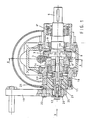
- Fig. 1 zeigt eine Antrebsaggregat im wesentlichen im Axialschnitt (teilweise versetzt gezeichnet, vgl. hierzu Fig. 2).
- Fig. 2 zeigt eine Stirnansicht des Antriebsaggregats von Fig. 1.
- Fig. 3 zeigt einen Schnitt gemäß der Linie A-A von Fig. 1.
- 1 shows an anti-cancer aggregate essentially in axial section (shown partially offset, see FIG. 2).
- FIG. 2 shows an end view of the drive unit from FIG. 1.
- FIG. 3 shows a section along the line AA from FIG. 1.
Das dargestellte Antriebsaggregat umfaßt ein mehrteiliges Gehäuse 1, an dem ein Antriebsmotor 2 angeflanscht ist, der eine Schneckenwelle 3 treibt, die mit einem Schneckenkranz 4 in Eingriff steht. Der Schneckenkranz 4 besitzt eine konische Innenbohrung, die mit einem konischen Ring 5 einer Rutschkupplung in Eingriff steht. Der konische Ring 5 sitzt über eine Paßfeder 6ʹ (Fig. 3) fest auf einer Abtriebswelle 6, die in dem Gehäuse 1 abgedichtet gelagert ist. Die Abtriebswelle 6 ist beidseitig über Wälzlager 6ʺ in dem Gehäuse 1 gelagert. Eine Druckscheibe 7, die axial gegenüber der Abtriebswelle 6 beweglich ist, wird über ein Tellerfederpaket 8 gegen den Schneckenkranz 4 gedrückt. Das Rutschmoment wird über eine Mutter 9, die auf die Abtriebswelle 6 geschraubt und am Außenumfang mit Axialnuten zu ihrer Verstellung versehen ist, und einen zwischen der Mutter 9 und dem Tellerfederpaket 8 angeordneten Ring 10 und die hierdurch bedingte Vorspannung des Tellerfederpakets 8, die auf die Druckscheibe 7 und damit auf die Reibfläche zwischen Schneckenkranz 4 und Ring 5 wirkt, eingstellt. Die Mutter 9 wird insbesondere durch einen am Umfang der Mutter einrastbaren, in Richtung zur Mutter 9 federvorgespannten Arretierstift beim Einstellen des Rutschmoments festgehalten, der in Betrieb mittels eines außerhalb des Gehäuses 1 betätigbaren Feststelleinrichtung in Nichteingriffsstellung zur Mutter 9 feststellbar ist.The drive unit shown comprises a multi-part housing 1, on which a
Das nach außen dichte Gehäuse 1 ist an einem Ende durch einen Einsatz 11 verschlossen, der eine Bohrung koaxial zur Abtriebswelle 6 aufweist. Diese Bohrung ist in ihrem mittleren Abschnitt mit Gewinde versehen und in ihrem gehäuseinnenseitigen Abschnitt erweitert. Sie nimmt eine Schraube 12 auf, die sich abgedichtet aus dem Einsatz 11 heraus- und bis zu dem erweiterten Abschnitt der Bohrung in diese hinein erstreckt. Die Schraube 12 steht mit einem Stößel 13 in Eingriff, der sich koaxial durch eine Bohrung 14 in dem benachbarten Ende der Abriebswelle 6 erstreckend bis in einen Schlitz 15, der sich radial durch die Abtriebswelle 6 erstreckt, ragt. In dem Schlitz 15 ist ein Querkeil 16 axial verschiebbar und durch den Schlitz 15 geführt angeordnet. Der Querkeil 16 steht über seine über den Durchmesser der Abtriebswelle 6 hinausragende Enden mit der Druckscheibe 7 einerseits und ferner mit dem zugewandten Ende des Stößels 13 andererseits in Eingriff. Abgesehen davon ist der Stößel 13 mit zwei Bunden 17 versehen, die zwischen sich ein Axialrillenkugellager 18 aufnehmen, von dem der Lagerring mit größerem Durchmesser von dem erweiterten Abschnitt der Bohrung des Einsatzes 11 aufgenommen und geführt wird.The outwardly sealed housing 1 is closed at one end by an
Das aus dem Einsatz 11 herausragende Ende der Schraube 12 ist mit einem Hebel 19 verbunden, der um eine vorbestimmte Winkelstellung verschwenkbar ist, wodurch die Schraube 12 aus ihrer in Fig. 1 dargestellten Ausgangsstellung einwärts gedreht wird. Hierdurch wird der Stößel 13 und damit der Querkeil 16 axial verschoben, wodurch die Rutschkupplung entlastet wird. Die Abtriebswelle 6 wird damit frei beweglich.The end of the
Zur Einstellung der axialen Position des Stößels 13 ist die Schraube 12 mit einer Bohrung versehen, die in einem gehäuseinnenseitigen erweiterten Abschnitt das zugewandte Ende des Stößels 13 aufnimmt und nach außen durch eine Schraube 20 dicht verschlossen ist. Zwischen der Schraube 20 und dem zugewandten Ende des Stößels 13 können eine oder mehrere Distanzstücke 21 angeordnet sein.To adjust the axial position of the
Der Einsatz 11 kann außenseitig an vorbestimmten Stellen Rastausnehmungen 22 aufweisen, in die eine von einer Schraube 23 getragene federvorgespannte Kugel 24 einrasten kann. Die Schraube 23 wird von dem Hebel 19 aufgenommen.The
Außerdem kann der Einsatz 11 Anschläge 25 aufweisen, die die Schwenkbewegung des Hebels 19 winkelmäßig begrenzen.In addition, the
Claims (8)
dadurch gekennzeichnet,
daß die antriebbare Welle (3) eine Schneckenwelle ist, die mit einem Schneckenkranz (4) in Eingriff steht,
daß die Kupplung eine Rutschkupplung mit einem den Schneckenkranz (4) beaufschlagenden, durch die Feder (8) vorgespannten Druckring (7) und einem konischen, mit einer im Gehäuse (1) gelagerten Abtriebswelle (6) fest verbundenen Ring (5), auf dem sich der Schneckenranz (4) befindet, ist,
daß die Abriebswelle (6) den Radialschlitz (15) zur axialen Führung des Querkeils (16), der an dem Druckring (7) auf der der Feder (8) abgewandten Seite angreift, besitzt und
daß der Stößel (13) über eine Schraube (12), die von einer Gewindebohrung im Gehäuse (1) koaxial zur Abtriebswelle (6) verdrehbar aufgenommen ist, mit dem Betätigungshebel (19), dessen Hebelweg über eine Einrichtung (20, 21) zur Einstellung der axialen Position des Stößels (13) justierbar ist, in Eingriff steht.1. Drive unit with a drivable shaft (3) arranged in a housing (1), which is operatively connected to a clutch also housed in the housing (1), the clutch being biased into engagement position via a spring (8) and via a a radial slot (15) axially guided cross wedge (16) and a plunger (13) acting on it and actuatable from the outside by an actuating lever (19) can be disengaged,
characterized,
that the driven shaft (3) is a worm shaft which is in engagement with a worm ring (4),
that the clutch has a slip clutch with a worm ring (4) acting on by the spring (8) biased pressure ring (7) and a conical, with an output shaft (6) mounted in the housing (1) ring (5) on which there is the snail ring (4),
that the abrasion shaft (6) has the radial slot (15) for axially guiding the transverse wedge (16) which engages the pressure ring (7) on the side facing away from the spring (8) and
that the plunger (13) via a screw (12) which is rotatably received by a threaded bore in the housing (1) coaxially to the output shaft (6) with the actuating lever (19), the lever path via a device (20, 21) for Setting the axial position of the plunger (13) is adjustable, is engaged.
Applications Claiming Priority (2)
| Application Number | Priority Date | Filing Date | Title |
|---|---|---|---|
| DE8629599U | 1986-11-05 | ||
| DE19868629599 DE8629599U1 (en) | 1986-11-05 | 1986-11-05 |
Publications (2)
| Publication Number | Publication Date |
|---|---|
| EP0266531A2 true EP0266531A2 (en) | 1988-05-11 |
| EP0266531A3 EP0266531A3 (en) | 1990-02-28 |
Family
ID=6799953
Family Applications (1)
| Application Number | Title | Priority Date | Filing Date |
|---|---|---|---|
| EP87113743A Withdrawn EP0266531A3 (en) | 1986-11-05 | 1987-09-19 | Drive assembly |
Country Status (2)
| Country | Link |
|---|---|
| EP (1) | EP0266531A3 (en) |
| DE (1) | DE8629599U1 (en) |
Cited By (4)
| Publication number | Priority date | Publication date | Assignee | Title |
|---|---|---|---|---|
| EP0446655A1 (en) * | 1990-03-16 | 1991-09-18 | W.u.H. Neukirchen GmbH & Co. KG | Self-locking worm gear for a high speed door drive |
| EP0657340A1 (en) * | 1993-12-07 | 1995-06-14 | Koyo Seiko Co., Ltd. | Power steering apparatus |
| WO2006036514A1 (en) * | 2004-09-23 | 2006-04-06 | Mtd Products Inc | Transmission for walk-behind lawn mower |
| DE19946484B4 (en) * | 1998-10-12 | 2010-11-25 | Magna Steyr Fuel Systems Gesmbh | Drive device for a closure device of a vehicle tank filler neck |
Citations (5)
| Publication number | Priority date | Publication date | Assignee | Title |
|---|---|---|---|---|
| DE476034C (en) * | 1925-12-11 | 1929-05-10 | Wilhelm Todt & Sohn | Friction clutch |
| DE2522293A1 (en) * | 1975-05-20 | 1976-12-02 | Tornado Elektromotorfab Gmbh | Worm wheel gear box - has integral shaft coupling with coupling sleeve studs located in worm wheel hub |
| US4274620A (en) * | 1978-09-30 | 1981-06-23 | Dieter Delwing | Anchor windlass |
| DE3123284A1 (en) * | 1981-06-12 | 1982-12-30 | Rhein-Getriebe Gmbh, 4005 Meerbusch | Slip clutch |
| FR2597558A3 (en) * | 1986-01-23 | 1987-10-23 | Stm Spa | Improvements to torque limiters for a motorised reduction gear |
-
1986
- 1986-11-05 DE DE19868629599 patent/DE8629599U1/de not_active Expired
-
1987
- 1987-09-19 EP EP87113743A patent/EP0266531A3/en not_active Withdrawn
Patent Citations (5)
| Publication number | Priority date | Publication date | Assignee | Title |
|---|---|---|---|---|
| DE476034C (en) * | 1925-12-11 | 1929-05-10 | Wilhelm Todt & Sohn | Friction clutch |
| DE2522293A1 (en) * | 1975-05-20 | 1976-12-02 | Tornado Elektromotorfab Gmbh | Worm wheel gear box - has integral shaft coupling with coupling sleeve studs located in worm wheel hub |
| US4274620A (en) * | 1978-09-30 | 1981-06-23 | Dieter Delwing | Anchor windlass |
| DE3123284A1 (en) * | 1981-06-12 | 1982-12-30 | Rhein-Getriebe Gmbh, 4005 Meerbusch | Slip clutch |
| FR2597558A3 (en) * | 1986-01-23 | 1987-10-23 | Stm Spa | Improvements to torque limiters for a motorised reduction gear |
Cited By (5)
| Publication number | Priority date | Publication date | Assignee | Title |
|---|---|---|---|---|
| EP0446655A1 (en) * | 1990-03-16 | 1991-09-18 | W.u.H. Neukirchen GmbH & Co. KG | Self-locking worm gear for a high speed door drive |
| EP0657340A1 (en) * | 1993-12-07 | 1995-06-14 | Koyo Seiko Co., Ltd. | Power steering apparatus |
| US5482128A (en) * | 1993-12-07 | 1996-01-09 | Koyo Seiko Co., Ltd. | Power steering apparatus |
| DE19946484B4 (en) * | 1998-10-12 | 2010-11-25 | Magna Steyr Fuel Systems Gesmbh | Drive device for a closure device of a vehicle tank filler neck |
| WO2006036514A1 (en) * | 2004-09-23 | 2006-04-06 | Mtd Products Inc | Transmission for walk-behind lawn mower |
Also Published As
| Publication number | Publication date |
|---|---|
| EP0266531A3 (en) | 1990-02-28 |
| DE8629599U1 (en) | 1987-01-02 |
Similar Documents
| Publication | Publication Date | Title |
|---|---|---|
| DE2522446C3 (en) | Safety slip clutch for hand drill | |
| DE2734630C2 (en) | Two-strand, continuously adjustable conical pulley belt drive with even load distribution | |
| DE1276498B (en) | Device for moving sliding windows, in particular in motor vehicle doors, with a crank drive and an electromotive, switchable drive | |
| DE2613065C3 (en) | Automatic coupling device for a handwheel | |
| DE2842814A1 (en) | BY MOTOR OR BY HAND, Possibly. REMOTE CONTROLLED ANCHOR WINCH | |
| DE4118941C2 (en) | Hub / shaft connection | |
| EP0266531A2 (en) | Drive assembly | |
| DE2322196C3 (en) | Adjustment device for the tensioning arrangement of a bevel pulley belt transmission | |
| DE2313895C2 (en) | Actuating device for valves | |
| DE2629279B2 (en) | Infinitely variable V-belt drive | |
| DE4441820B4 (en) | Hammer and / or percussion hammer | |
| DE19757500C1 (en) | Frictional slip coupling for electrical drives for lifting tools, esp. for heavy chain hoists | |
| DE3426428C1 (en) | Apparatus for the auxiliary actuation of drives, in particular gate or door drives | |
| DE4425272C2 (en) | Hoist | |
| DE10318674A1 (en) | Operating unit for a component which is movable on base part against spring tension, comprises a coupling which has a drive clutch wheel rotatable about a rotation axis | |
| DE3123284C2 (en) | Slip clutch | |
| DE60109744T2 (en) | TORQUE SENSOR | |
| WO1999007570A1 (en) | Front-axle output of an automatic transmission | |
| DE3432419C2 (en) | Gearbox with emergency shutdown | |
| DE3606039C2 (en) | ||
| DE3213835A1 (en) | OVERLOAD CLUTCH FOR ROTARY TRANSMISSIONS | |
| EP0897072B1 (en) | Clutch and brake device for a drive unit | |
| DE3830197C1 (en) | Powered screwing tool with a torque-limiting device | |
| AT233797B (en) | Self-locking device for operating roller shutters | |
| DE2263229C3 (en) | Infinitely adjustable conical pulley belt drive with rotary |
Legal Events
| Date | Code | Title | Description |
|---|---|---|---|
| PUAI | Public reference made under article 153(3) epc to a published international application that has entered the european phase |
Free format text: ORIGINAL CODE: 0009012 |
|
| AK | Designated contracting states |
Kind code of ref document: A2 Designated state(s): DE FR IT |
|
| PUAL | Search report despatched |
Free format text: ORIGINAL CODE: 0009013 |
|
| AK | Designated contracting states |
Kind code of ref document: A3 Designated state(s): DE FR IT |
|
| STAA | Information on the status of an ep patent application or granted ep patent |
Free format text: STATUS: THE APPLICATION HAS BEEN WITHDRAWN |
|
| 18W | Application withdrawn |
Withdrawal date: 19900614 |
|
| RIN1 | Information on inventor provided before grant (corrected) |
Inventor name: BANNIER, GEORG |