EP0266271B1 - Verfahren für die Membrantrennung von Gasmischungen - Google Patents
Verfahren für die Membrantrennung von Gasmischungen Download PDFInfo
- Publication number
- EP0266271B1 EP0266271B1 EP87402408A EP87402408A EP0266271B1 EP 0266271 B1 EP0266271 B1 EP 0266271B1 EP 87402408 A EP87402408 A EP 87402408A EP 87402408 A EP87402408 A EP 87402408A EP 0266271 B1 EP0266271 B1 EP 0266271B1
- Authority
- EP
- European Patent Office
- Prior art keywords
- gas
- membrane
- sweep
- gases
- partial pressure
- Prior art date
- Legal status (The legal status is an assumption and is not a legal conclusion. Google has not performed a legal analysis and makes no representation as to the accuracy of the status listed.)
- Expired - Lifetime
Links
Images

Classifications
-
- B—PERFORMING OPERATIONS; TRANSPORTING
- B01—PHYSICAL OR CHEMICAL PROCESSES OR APPARATUS IN GENERAL
- B01D—SEPARATION
- B01D53/00—Separation of gases or vapours; Recovering vapours of volatile solvents from gases; Chemical or biological purification of waste gases, e.g. engine exhaust gases, smoke, fumes, flue gases, aerosols
- B01D53/22—Separation of gases or vapours; Recovering vapours of volatile solvents from gases; Chemical or biological purification of waste gases, e.g. engine exhaust gases, smoke, fumes, flue gases, aerosols by diffusion
-
- Y—GENERAL TAGGING OF NEW TECHNOLOGICAL DEVELOPMENTS; GENERAL TAGGING OF CROSS-SECTIONAL TECHNOLOGIES SPANNING OVER SEVERAL SECTIONS OF THE IPC; TECHNICAL SUBJECTS COVERED BY FORMER USPC CROSS-REFERENCE ART COLLECTIONS [XRACs] AND DIGESTS
- Y02—TECHNOLOGIES OR APPLICATIONS FOR MITIGATION OR ADAPTATION AGAINST CLIMATE CHANGE
- Y02C—CAPTURE, STORAGE, SEQUESTRATION OR DISPOSAL OF GREENHOUSE GASES [GHG]
- Y02C20/00—Capture or disposal of greenhouse gases
- Y02C20/40—Capture or disposal of greenhouse gases of CO2
Definitions
- This invention relates to the field of separation of gas mixtures and particularly to the separation of a single component from a mixture of gases.
- a semipermeable membrane and a purge gas are used.
- the purge gas contains at least one of the gases desired to be retained on the feed side of the membrane. The purpose of this is to minimize the passage across the membrane of the gases to be retained and encourage the passage across the membrane from the feed side to the purge side of the gas component to be separated.
- the prior art has separated gases from mixtures using semipermeable membranes from a feed side to a diffusion side by drawing a vacuum on the diffusion side.
- Another method commonly used is to pass a feed gas on one side of a semipermeable membrane and to pass a purge gas on the opposite side.
- a high pressure is used for the feed gas than for the purge gas to encourage the diffusion of molecules from the feed side to the purge side. If the concentration of the desired gases to be diffused is less on the sweep side, then the differential in pressure will cause diffusion of such gases from the feed side to the purge side.
- the method does not permit the passage of a single element from a mixture of gases since generally the partial pressure of all the components on one side of the membrane are less on the sweep side as well as the concentration thereof.
- Another method includes using a very thin semipermeable membrane which is selectably permeable for a specific gas such as hydrogen.
- a specific gas such as hydrogen.
- the feed gas is passed in contact with the semipermeable membrane and only the molecule which is selectively permitted to pass will go through the membrane.
- This method selection has limited application since such highly selective membranes are limited to very few gas elements at the present time.
- the present invention is based on the concept that, using a semipermeable membrane, operating under typical conditions of feed gas injection into the high pressure side of the membrane, through the use of a purge gas, the partial pressure differential across the membrane of gas components not present in the purge gas will increase, resulting in higher relative mass transfer of those gas components through the membrane.
- the use of the purge gas decreases the partial pressure differential across the membrane of those gas components present in the purge gas resulting in a lower relative mass transfer through the membrane. This process can be used to more selectively transfer specific gas components through the membrane.
- certain gas components present in gas mixtures on both sides of a semipermeable membrane can have their respective partial pressures balanced so that there is substantially a zero partial pressure differential. The remaining gas components then will diffuse in either direction across the membrane depending upon their differential partial pressures.
- This invention can find specific application in the field of fermentation sciences in which air enriched with oxygen is passed through a fermentation vat by any suitable means for purposes of speeding up the fermentation reaction.
- This air/oxygen enrichment produces off-gases from the fermentation vat consisting, for example, of 30% by volume of oxygen, 55% by volume of nitrogen, and 15% by volume of carbon dioxide. In the past, such gases were simply vented to the atmosphere.
- these gases maintained at a pressure of for example 517 KPa, are passed on one side of a semipermeable membrane and a sweep gas or purge gas comprising compressed air at preferably about 360 KPa is passed on the opposite side of the membrane.
- a sweep gas or purge gas comprising compressed air at preferably about 360 KPa is passed on the opposite side of the membrane.
- the partial pressure differential of nitrogen on both sides of the membrane is essentially zero. This causes the minimal passage of oxygen and nitrogen in either direction across the membrane and maximizes the passage of the carbon dioxide from the feed gas side to the sweep gas side.
- the resulting residue gas on the feed side is slightly depleted in oxygen and greatly reduced in carbon dioxide to the extent of less than 1% carbon dioxide.
- This resulting gas can then be recycled through fermentation vat with the addition some oxygen to make up for the volume of gas lost in the diffusion through the semipermeable membrane.
- the residue gas which is recycled requires lesser amounts of oxygen enrichment than would be required without recycling of the gases. It is necessary to remove the carbon dioxide since percentages above about 5% can stop the fermentation reaction.
- the advantageous results which are obtained by this method include reduced costs in that less oxygen is required for enrichment of the gases which are pumped through the fermentation vat. Furthermore, the pressure of the compresses air used as the sweep gas is especially selected to minimize the partial pressure of the nitrogen across the membrane. Not only does this encourage the diffusion of carbon dioxide into the sweep gas, but also there is significant energy conservation.
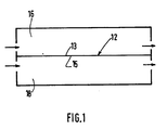
- FIG. 1 of the drawings there is shown schematically a semipermeable membrane 12 having a feed side 13 and a sweep side 15 disposed in a chamber 14.
- the membrane 12 bisects the chamber 14 dividing it into two compartments, a feed gas compartment 16 and a sweep gas compartment 18.
- a gas mixture containing one or more gases to be separated therefrom is passed through the feed gas compartment 16 of chamber 14 into contact with the feed side 13 of the membrane 12.
- the gas mixture on the feed side is comprised of at least one gas component to be separated and at least one gas component to be retained.
- the purge gas is comprised of at least one gas component of the same identity as one of the gas components to be retained on the feed side.
- the gas or gases to be separated from the gas mixture on the feed side can be present on the sweep side as long as the molar concentration of such gas is substantially less on the sweep side and the partial pressure is greater on the feed side.
- the invention steps comprise selecting a feed gas pressure and a sweep gas pressure which provides substantially a zero partial pressure differential across the membrane for at least one gas component to be retained which is present on the feed gas side and on the sweep gas side. This substantially minimizes passage of the retained gas component in either direction across the membrane.
- concentration of the gas to be separated is present in substantially greater molar concentrations on the feed side, its partial pressure will be higher on the feed side. This causes the gas component to be separated to pass from the feed side to the sweep side of the membrane.
- any type of semipermeable membrane can be used in any convenient form.
- a single membrane or a bank of membranes can be employed as can membranes in the form of hollow fibers arranged in bundles.
- Liquid membranes can also be used.
- Such membranes can be made of cellulose acetate, polysulfones, polyimides, polyamides, silicones, polytetrafluoroethylenes and the like.
- the identity of the membrane is not critical to the invention process.
- FIG. 2 shows a schematic representation of a preferred embodiment of the invention.
- Compressed air from a compressor 24 passes through a valve 26 where it enters a conduit 28.
- Liquid oxygen from a tank 30 enters conduit 28 by means of valve 32.
- the resulting mixture of preferably about 40% to about 50% oxygen, 55% nitrogen and ⁇ 1% carbon dioxide at a pressure of for example 517 KPa is bubbled through a fermentation vat 34 by means of a tube 36.
- Tube 36 introduces the gas mixture near the bottom of the vat 34.
- the introduction of the gas mixture causes the fermention in the vat to speed up.
- the oxygen is consumed in the biological processes which take place.
- the off gases escaping from the vat 34 are comprised of for example, 30% to 40% oxygen, 55% nitrogen and 5-15% carbon dioxide.
- the off gases excape from the vat 34 through outlet 38 where they enter conduit 40.
- a portion of the gas is diverted through valve 42 to carbon dioxide and oxygen analyzer 44.
- the off gases are analyzed for percentage of oxygen and carbon dioxide. The amount of the nitrogen is found by difference.
- the off gasses are then passed through compressor 46 to bring the pressure to for example 517 KPa (75 psia) since some pressure losses are experience during the reaction. From the compresser 46, the off gases are passed into a chamber 48 for separation of the carbon dioxide.
- the exact pressure of the feed gas and of the sweep gas is not critical.
- the invention lies in selecting the respective pressures to balance the partial pressure of the component to be retained in the feed gas mixture which is present on both sides of the membrane.
- Chamber 48 contains an inlet 50 and an outlet 52 for the respective introduction and withdrawal of off gases into a central chamber 51.
- Another inlet 54 for purge or sweep gas communicates with a plenum 56.
- a plurality of bundles of hollow fibers 58 are disposed within the chamber 51 and are sealed from end communication by means of layers 53 and 55 within which the bundles are sealably fixed so that communication is blocked between plenum 56 and central chamber 51 except by passage through the hollow fibers.
- One end of each of the bundles opens into the plenum 56, and the opposite end of each of the bundles opens into a plenum 60 which communicates with an outlet 62.
- a compressor 64 introduces compressed air sweep gas through a valve 66 at a pressure of about 360 KPa into inlet 54 to plenum 56. Since the plenum 56 is sealed with respect to the inner central chamber 51, the air passes through the central bore of each of the hollow fibers of bundles 58. At the same time, the off gases at a pressure of 517 KPa pass into central chamber 51 of chamber 48 by means of inlet 50.
- the off gases contact the exterior surfaces of the hollow fiber bundles which have the sweep gas in the form of compressed air passing therethrough. With these relative pressures, the partial pressure of nitrogen across the hollow fiber membrane is essentially zero. This precludes passage of nitrogen gas in either direction across the fiber membranes.
- the partial pressure of carbon dioxide is substantially greater on the feed or off gas side so that almost all of the carbon dioxide diffuses through the fiber membranes and is carried away in the sweep gas stream.
- the partial pressure of oxygen is somewhat greater on the off gas or feed side of the fiber membranes so that some oxygen will diffuse into the sweep gas. However, this passage is further minimized by the fact that the partial pressure differential across the membrane of oxygen is less than the partial pressure differential across the membrane of carbon dioxide. This results in the carbon dioxide being preferentially diffused.
- the residue gas which exits inner chamber 51 by means of outlet 52 reenters conduit 28 where additional oxygen is added to it to bring the oxygen percent up to about 40% to about 50%. In this manner the reaction can proceed continuously as long as desired.
- the feed gas can be made to pass through the bores of the hollow fibers and the sweep or purge gas can be passed into contact with the exterior surfaces of the fiber bundles. It is a matter of passing the feed gas on one side of the membrane surface and the sweep gas on the opposite side.
- the invention should not be limited to which side is selected since both sides can be employed.
- the concentration does not need to be calculated.
- To calculate the required pressure needed on the sweep gas side it is necessary to divide the partial pressure of nitrogen on the feed side by the concentration of nitrogen on the sweep side. This equals the required feed pressure of the sweep gas in order to provide equal partial pressures across the semipermeable membrane.
- a feed gas pressure of 517 KPa provides a partial pressure at 55 % nitrogen of .55 x 517 KPa which equals 284 KPa partial pressure of nitrogen.
- the partial pressure of 284 KPa divided by .79 equals a required sweep gas pressure of 360 KPa.
- a sweep gas pressure of 360 KPa x 79 % nitrogen gives a nitrogen partial pressure on the sweep side of 284 KPa. This is equal to the partial pressure of nitrogen on the feed gas side. This balances the nitrogen partial pressure across the membrane to that the differential is essentially zero.
- a concentration of 15 % carbon dioxide on the feed side gives 77,5 KPa partial pressure of carbon dioxide on the feed side (.15 x 517 KPa) and, since the sweep gas contains no carbon dioxide there is a approximately a 77,5 KPa partial pressure differential if it is assured that there is not carbon dioxide on the sweep gas side. In actuality since the gas will be continously diffusing, the partial pressure differential is slightly less. The partial pressure differential causes the carbon dioxide to pass to the sweep gas side from the feed gas side.
- Substantially the apparatus shown in Figure 2 was used for increasing fermentation. Initially compressed air was enriched with oxygen to provide a concentration of 40% oxygen, 55% nitrogen and ⁇ 1 % carbon dioxide. This gas was continuously introduced into a fermentation vat at a pressure of 517 KPa. The off gases were analyzed and found to contain 55% nitrogen, 30% oxygen, and 15% carbon dioxide.
- the gases were then passed through a compressor to bring the pressure to 517 KPa.
- the pressurized off gas mixture was then made to contact the exterior surfaces of hollow fiber membrane bundles.
- compressed air containing 21% oxygen and 79% nitrogen was passed through the interior bores of the hollow fiber membrane bundles.
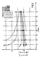
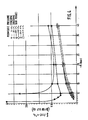
- Figures 3 and 4 show graphs which demonstrate the cost savings obtained following the above example by using a purge or sweep gas and a membrane by comparison with using only a vacuum across the membrane.
- Figure 3 shows the use of a cellulose acetate membrane and Figure 4 shows use of a polysulfone membrane.
- the y axis represents the cost in dollars for amounts of oxygen which are recovered and the x axis shows the variation in pressure shown in atmospheres.
- the solid lines representing the use of a vacuum is far more expensive than when a purge or sweep gas is used as represented by the dotted lines even at pressures as high as 1034 KPa.
- a further feature of the invention comprises balancing the partial pressure of a first gas to be retained to provide as close as possible substantially equal partial pressures across the membrane while at the same time providing a partial pressure differential across the membrane for a second gas to be retained, which partial pressure differential is less than the partial pressure differential of the gas to be separated. This will effectively maximize diffusion across the membrane of the gas to be separated while minimizing diffusion across the membrane of the gases to be retained.
- the partial pressure of nitrogen is balanced to the extent possible across the membrane while at the same time keeping the partial pressure differential across the membrane of carbon dioxide greater than the partial pressure differential across the membrane of oxygen. This causes the carbon dioxide to be preferentially diffused to the sweep side while diffusion of the nitrogen and oxygen in either direction is minimized.
Landscapes
- Chemical & Material Sciences (AREA)
- Engineering & Computer Science (AREA)
- Analytical Chemistry (AREA)
- General Chemical & Material Sciences (AREA)
- Oil, Petroleum & Natural Gas (AREA)
- Chemical Kinetics & Catalysis (AREA)
- Separation Using Semi-Permeable Membranes (AREA)
- Hydrogen, Water And Hydrids (AREA)
Claims (7)
- Verfahren zur kontinuierlichen, im wesentlichen vollständigen Abtrennung mindestens einer Gaskomponente aus einer Gasmischung zur Erzeugung eines Restgases, das im wesentlichen von diesen Gaskomponenten befreit ist, umfassend die Schritte:
Schaffung einer semipermeablen Membran mit einer Zuführgasseite und einer Abführgasseite;
Kontaktierung der Zuführgasseite der semipermeablen Membran mit einere Zuführgasmischung, die mindestens ein Gas enthält, das zurückgehalten werden soll, und mindestens ein Gas, das daraus abgetrennt werden soll;
gleichzeitiges Kontaktieren der Abführseite der semipermeablen Membran mit einem Abführgas, das einen niedrigeren Druck als das Zuführgas aufweist;
Abziehen eines Restgases nach Kontakt mit der Zuführseite der Membran, das im wesentlichen von den abzutrennenden Gasen befreit ist;
Abziehen eines Durchdringungsgases nach Kontakt mit der Abführseite der Membran, das im wesentlichen mit den abzutrennenden Gasen angereichert ist;
dadurch gekennzeichnet, dass es weiterhin die Einstellung des Partialdrucks von einer der auf der Zuführgasseite zurückzuhaltenden Gaskomponenten, die auf beiden Seiten der Membran vorliegt, umfasst, so dass die Partialdruckdifferenz auf beiden Seiten der Membran im wesentlichen Null ist. - Verfahren nach Anspruch 1, wobei die Zuführgasmischung zwei zurückzuhaltende Gase enthält, die auf der Abführgasseite vorhanden sind, dadurch gekennzeichnet, dass das Verfahren weiterhin die Schritte umfasst:
Einstellen des Partialdrucks eines ersten, zurückzuhaltenden Gases, um auf beiden Seiten der Membran soweit wie möglich im wesentlichen gleiche Partialdrücke zu schaffen, und gleichzeitig Schaffen einer Partialdruckdifferenz über die Membran für ein zweites, zurückzuhaltendes Gas, wobei die Partialdruckdifferenz geringer ist als die Partialdruckdifferenz des abzutrennenden Gases, um die Diffusion des abzutrennenden Gases über die Membran zu maximieren, während die Diffusion der zurückzuhaltenden Gase über die Membran minimiert wird. - Verfahren nach Anspruch 1 oder 2, dadurch gekennzeichnet, dass das Verfahren weiterhin die Schritte umfasst:
Schaffung eines Gehäuses mit darin angeordneter Membranvorrichtung, die das Gehäuse in eine erste und eine zweite Kammer auftrennt;
Treiben der Zuführgasmischung durch die erste Kammer unter Kontaktieren mit der Membran während gleichzeitigem Führen der Abführgasmischung durch die zweite Kammer;
Abziehen des Restgases aus der ersten Kammer, das im wesentlichen von den abzutrennenden Gasen befreit ist;
Abziehen des Durchgangsgases von der zweiten Kammer, das im wesentlichen mit den abzutrennenden Gasen angereichert ist. - Verfahren nach einem der Ansprüche 1 bis 3, dadurch gekennzeichnet, dass sich die Zuführgasmischung aus Stickstoff, Sauerstoff und Kohlendioxid zusammensetzt,
die zurückzuhaltenden Gaskomponenten Stickstoff und Sauerstoff umfassen,
die abzutrennende Gasekomponente Kohlendioxid umfasst, und
die zurückzuhaltende Gaskomponente, deren Partialdruck eingestellt wird, um im wesentlichen eine Partialdruckdifferenz über die Membran von Null zu schaffen, Stickstoff ist. - Verfahren gemäss einem der Ansprüche 1 bis 4, dadurch gekennzeichnet, dass das Abführgas Luft ist.
- Verfahren nach einem der Ansprüche 1 bis 4, dadurch gekennzeichnet, dass es in einem Fermentationsprozess eingesetzt wird.
- Vorrichtung zur Durchführung des Verfahrens nach Anspruch 6, gekennzeichnet durch:
eine Quelle für Druckluft;
eine Quelle für Sauerstoff;
eine Fermentationsküpe, die einen im wesentlichen geschlossenen Kessel mit einem Einlass und einem Auslass umfasst;
Vorrichtungen innerhalb der Küpe in Verbindung mit dem Einlass zur Einführung der Gase;
erste Führvorrichtungen in Verbindung mit der Druckluftquelle und der Sauerstoffquelle und mit den Vorrichtungen innerhalb der Küpe zur Einführung der Gase;
zweite Führvorrichtungen in Verbindung mit dem Auslass der Küpe;
einen Kohlenstoffdioxid- und Sauerstoffanalysator in Verbindung mit den zweiten Führvorrichtungen;
einen Kompressor in Verbindung mit den zweiten Führvorrichtungen zur Verdichtung von durchströmendem Gas;
ein Gehäuse;
eine semipermeable Membran, die innerhalb des Gehäuses angeordnet ist, und die das Gehäuse in ein erstes und zweites Trennabteil, die jeweils einen Einlass und einen Auslass aufweisen, aufteilt, wobei die Abteile nur durch den Durchfluss über die Membran in Verbindung stehen;
dritte Führvorrichtungen in Verbindung mit dem Kompressor und mit dem Einlass des ersten Abteils;
vierte Führvorrichtungen in Verbindung mit der Druckluftquelle und dem Einlass des zweiten Abteils des Gehäuses;
fünfte Führvorrichtungen in Verbindung mit dem Auslass des ersten Abteils des Gehäuses und mit den ersten Führvorrichtungen zur Leitung des Restgases von dem ersten Gehäuse zurück zu der Küpe zur Wiederverwendung.
Priority Applications (1)
| Application Number | Priority Date | Filing Date | Title |
|---|---|---|---|
| AT87402408T ATE67937T1 (de) | 1986-10-27 | 1987-10-26 | Verfahren fuer die membrantrennung von gasmischungen. |
Applications Claiming Priority (2)
| Application Number | Priority Date | Filing Date | Title |
|---|---|---|---|
| PCT/US1986/002296 WO1990007372A1 (en) | 1986-10-27 | 1986-10-27 | Process for membrane separation of gas mixtures |
| WOPCT/US86/02296 | 1986-10-27 |
Publications (2)
| Publication Number | Publication Date |
|---|---|
| EP0266271A1 EP0266271A1 (de) | 1988-05-04 |
| EP0266271B1 true EP0266271B1 (de) | 1991-10-02 |
Family
ID=22195692
Family Applications (1)
| Application Number | Title | Priority Date | Filing Date |
|---|---|---|---|
| EP87402408A Expired - Lifetime EP0266271B1 (de) | 1986-10-27 | 1987-10-26 | Verfahren für die Membrantrennung von Gasmischungen |
Country Status (8)
| Country | Link |
|---|---|
| US (1) | US4834779A (de) |
| EP (1) | EP0266271B1 (de) |
| JP (1) | JPS63178823A (de) |
| AT (1) | ATE67937T1 (de) |
| CA (1) | CA1315705C (de) |
| DE (1) | DE3773462D1 (de) |
| ES (1) | ES2025187B3 (de) |
| WO (1) | WO1990007372A1 (de) |
Families Citing this family (29)
| Publication number | Priority date | Publication date | Assignee | Title |
|---|---|---|---|---|
| FR2636341A1 (fr) * | 1988-09-12 | 1990-03-16 | Air Liquide | Procede et installation de recuperation des hydrocarbures les plus lourds d'un melange gazeux |
| GB8830107D0 (en) * | 1988-12-23 | 1989-02-22 | Boc Group Plc | Gas separation |
| US4931070A (en) * | 1989-05-12 | 1990-06-05 | Union Carbide Corporation | Process and system for the production of dry, high purity nitrogen |
| US5034025A (en) * | 1989-12-01 | 1991-07-23 | The Dow Chemical Company | Membrane process for removing water vapor from gas |
| US5149340A (en) * | 1991-03-12 | 1992-09-22 | Marathon Oil Company | Process and apparatus for separating impurities from hydrocarbons |
| US5205842A (en) * | 1992-02-13 | 1993-04-27 | Praxair Technology, Inc. | Two stage membrane dryer |
| US5336298A (en) * | 1993-03-29 | 1994-08-09 | Air Products And Chemicals, Inc. | Polyelectrolyte membranes for the separation of acid gases |
| TW314512B (de) * | 1993-09-20 | 1997-09-01 | Shell Int Research | |
| NL9401233A (nl) * | 1994-03-25 | 1995-11-01 | Tno | Werkwijze voor membraangasabsorptie. |
| CA2158236A1 (en) * | 1994-09-14 | 1996-03-15 | Dwayne T. Friesen | Organic and inorganic vapor permeation by countercurrent condensable sweep |
| CA2170190A1 (en) * | 1995-03-07 | 1996-09-08 | Dwayne T. Friesen | Volatile organic component removal by membrane separation using countercurrent sweep gas |
| US5611845A (en) * | 1995-08-22 | 1997-03-18 | Undersea Breathing Systems, Inc. | Oxygen enriched air generation system |
| DE19533407C1 (de) * | 1995-09-09 | 1997-02-06 | Dornier Gmbh | Verfahren und Vorrichtung zur Abtrennung von Kohlendioxid |
| US5843209C1 (en) * | 1996-08-14 | 2001-05-15 | Bend Res Inc | Vapor permeation system |
| NL1006013C2 (nl) * | 1997-05-09 | 1998-11-10 | Tno | Inrichting en werkwijze voor het uitvoeren van membraan-gas/vloeistofabsorptie bij verhoogde druk. |
| US20040000232A1 (en) * | 2001-11-13 | 2004-01-01 | Van Horne William J. | Device and method for exchanging oxygen and carbon dioxide between a gas and an aqueous liquid |
| US7318854B2 (en) * | 2004-10-29 | 2008-01-15 | New Jersey Institute Of Technology | System and method for selective separation of gaseous mixtures using hollow fibers |
| US7517388B2 (en) * | 2006-05-15 | 2009-04-14 | Generon Igs, Inc. | Air separation membrane module with variable sweep stream |
| US20080011161A1 (en) * | 2006-07-17 | 2008-01-17 | General Electric Company | Carbon dioxide capture systems and methods |
| US20080127632A1 (en) * | 2006-11-30 | 2008-06-05 | General Electric Company | Carbon dioxide capture systems and methods |
| JP6096513B2 (ja) * | 2009-12-17 | 2017-03-15 | コーニンクレッカ フィリップス エヌ ヴェKoninklijke Philips N.V. | プラズマポンプ及び膜による酸素分離方法並びにシステム |
| US9856769B2 (en) | 2010-09-13 | 2018-01-02 | Membrane Technology And Research, Inc. | Gas separation process using membranes with permeate sweep to remove CO2 from combustion exhaust |
| US9140186B2 (en) * | 2010-09-13 | 2015-09-22 | Membrane Technology And Research, Inc | Sweep-based membrane gas separation integrated with gas-fired power production and CO2 recovery |
| US9005335B2 (en) * | 2010-09-13 | 2015-04-14 | Membrane Technology And Research, Inc. | Hybrid parallel / serial process for carbon dioxide capture from combustion exhaust gas using a sweep-based membrane separation step |
| US8685142B2 (en) * | 2010-11-12 | 2014-04-01 | The Texas A&M University System | System and method for efficient air dehumidification and liquid recovery with evaporative cooling |
| US8641806B2 (en) * | 2010-11-12 | 2014-02-04 | The Texas A&M University System | Systems and methods for multi-stage air dehumidification and cooling |
| US9592171B2 (en) | 2011-08-25 | 2017-03-14 | Undersea Breathing Systems, Inc. | Hyperbaric chamber system and related methods |
| US9782718B1 (en) | 2016-11-16 | 2017-10-10 | Membrane Technology And Research, Inc. | Integrated gas separation-turbine CO2 capture processes |
| CN112358049B (zh) * | 2020-11-10 | 2023-03-24 | 中恒新材料科技(山东)有限责任公司 | 以特种气体分离膜为基材滤料的膜生物反应器及其处理废水的方法 |
Citations (7)
| Publication number | Priority date | Publication date | Assignee | Title |
|---|---|---|---|---|
| US3350844A (en) * | 1964-09-21 | 1967-11-07 | Gen Electric | Process for the separation or enrichment of gases |
| US3604246A (en) * | 1965-09-14 | 1971-09-14 | Minnesota Mining & Mfg | Permeability testing apparatus and method |
| US3661724A (en) * | 1970-04-02 | 1972-05-09 | Beckman Instruments Inc | Closed loop hygrometry |
| US3823529A (en) * | 1973-02-23 | 1974-07-16 | Standard Oil Co | Process for separating carbon monoxide |
| US4060566A (en) * | 1975-11-19 | 1977-11-29 | Standard Oil Company (Indiana) | Membrane process for separating materials |
| US4330633A (en) * | 1980-08-15 | 1982-05-18 | Teijin Limited | Solid electrolyte |
| GB2139110A (en) * | 1982-12-27 | 1984-11-07 | Gen Electric | Water vapor exchange system |
Family Cites Families (25)
| Publication number | Priority date | Publication date | Assignee | Title |
|---|---|---|---|---|
| US1496757A (en) * | 1920-07-26 | 1924-06-03 | Goodyear Tire & Rubber | Process of separating gases |
| DE1252185B (de) * | 1962-08-24 | 1967-10-19 | Engelhard Industries, Inc., Newark, NJ. (V. St. A.) | Verfahren zur Gewinnung von Wasserstoff aus einem wasserstoffhaltigen Gasgemisch |
| US3489144A (en) * | 1967-02-13 | 1970-01-13 | Gen Electric | Closed rebreather - respirator circuit for renovation and supply of oxygen/nitrogen gas mixture |
| US3494174A (en) * | 1968-01-30 | 1970-02-10 | Varian Associates | Gas chromatography apparatus |
| US3545931A (en) * | 1968-08-28 | 1970-12-08 | Monsanto Co | Ammonia analysis system |
| US3674435A (en) * | 1970-06-05 | 1972-07-04 | Environment One Corp | Low concentration constituent of gaseous mixture selective converter and detector |
| FR2148903A5 (de) * | 1971-08-10 | 1973-03-23 | Air Liquide | |
| US3735559A (en) * | 1972-02-02 | 1973-05-29 | Gen Electric | Sulfonated polyxylylene oxide as a permselective membrane for water vapor transport |
| GB1440963A (en) * | 1973-04-30 | 1976-06-30 | Skarstrom C W | Process for separating a component from a fluid mixture |
| US3925037A (en) * | 1974-02-04 | 1975-12-09 | Gen Electric | High pressure membrane package construction |
| US3923461A (en) * | 1974-06-07 | 1975-12-02 | Meloy Lab | Apparatus and method employing gas-permeable membrane for separating, diluting, or concentrating molecular species |
| US4080288A (en) * | 1976-04-08 | 1978-03-21 | Daniel Pilson | Symbiotic membrane systems |
| US4187086A (en) * | 1977-06-15 | 1980-02-05 | General Electric Company | Packaged membrane system and replenishment method |
| NL182796C (nl) * | 1978-03-20 | 1988-05-16 | Monsanto Co | Werkwijze voor het recirculeren van waterstof bij de bereiding van ammoniak. |
| CH651587A5 (de) * | 1980-11-18 | 1985-09-30 | Chemap Ag | Verfahren und vorrichtung zur submersen zuechtung von zellkulturen. |
| US4508548A (en) * | 1981-08-04 | 1985-04-02 | The Garrett Corporation | Air oxygen and nitrogen concentration device |
| DE3134539C2 (de) * | 1981-09-01 | 1984-10-31 | Leonid Nikolaevič Čekalov | Verfahren zur biologischen Reinigung von Abwasser mit Belebtschlamm |
| JPS6015303A (ja) * | 1983-07-06 | 1985-01-26 | Three T:Kk | 商品の自動配送方法 |
| DE3337572A1 (de) * | 1983-10-15 | 1985-04-25 | Linde Ag, 6200 Wiesbaden | Verfahren und vorrichtung zum abtrennen einer komponente aus einem gasgemisch |
| JPS60137806A (ja) * | 1983-12-23 | 1985-07-22 | Toyobo Co Ltd | 酸素濃度の制御方法 |
| JPS60183025A (ja) * | 1984-03-02 | 1985-09-18 | Mitsubishi Chem Ind Ltd | 水蒸気分離法 |
| JPS60197298A (ja) * | 1984-03-19 | 1985-10-05 | Matsushita Electric Ind Co Ltd | メタン発酵装置 |
| US4750918A (en) * | 1985-05-28 | 1988-06-14 | The Trustees Of The Stevens Institute Of Technology | Selective-permeation gas-separation process and apparatus |
| JPH0724839B2 (ja) * | 1986-05-13 | 1995-03-22 | 株式会社明電舍 | メタン発酵の制御方法 |
| EP0263212B1 (de) * | 1986-10-08 | 1990-12-27 | Ube Industries, Ltd. | Verfahren zur Entfernung von Wasserdampf aus einem wasserdampfhaltigen Gas |
-
1986
- 1986-10-27 US US07/193,103 patent/US4834779A/en not_active Expired - Lifetime
- 1986-10-27 WO PCT/US1986/002296 patent/WO1990007372A1/en not_active Ceased
-
1987
- 1987-10-23 JP JP62266703A patent/JPS63178823A/ja active Pending
- 1987-10-26 CA CA000550254A patent/CA1315705C/en not_active Expired - Fee Related
- 1987-10-26 ES ES87402408T patent/ES2025187B3/es not_active Expired - Lifetime
- 1987-10-26 DE DE8787402408T patent/DE3773462D1/de not_active Expired - Lifetime
- 1987-10-26 EP EP87402408A patent/EP0266271B1/de not_active Expired - Lifetime
- 1987-10-26 AT AT87402408T patent/ATE67937T1/de not_active IP Right Cessation
Patent Citations (7)
| Publication number | Priority date | Publication date | Assignee | Title |
|---|---|---|---|---|
| US3350844A (en) * | 1964-09-21 | 1967-11-07 | Gen Electric | Process for the separation or enrichment of gases |
| US3604246A (en) * | 1965-09-14 | 1971-09-14 | Minnesota Mining & Mfg | Permeability testing apparatus and method |
| US3661724A (en) * | 1970-04-02 | 1972-05-09 | Beckman Instruments Inc | Closed loop hygrometry |
| US3823529A (en) * | 1973-02-23 | 1974-07-16 | Standard Oil Co | Process for separating carbon monoxide |
| US4060566A (en) * | 1975-11-19 | 1977-11-29 | Standard Oil Company (Indiana) | Membrane process for separating materials |
| US4330633A (en) * | 1980-08-15 | 1982-05-18 | Teijin Limited | Solid electrolyte |
| GB2139110A (en) * | 1982-12-27 | 1984-11-07 | Gen Electric | Water vapor exchange system |
Non-Patent Citations (5)
| Title |
|---|
| C.Y. Pan & H.W. Habgood "An Analysis of the Single Stage Gaseous Permeation Process", Ind. Eng. Chem., Fundam., 13(4), pp. 323-331 (1974) * |
| Hwang & Kammermeyer, "Membranes in Separations", Krieger Publishing Company Inc., Florida U.S.A., pp. 86-87 (1984) * |
| Professor Patrick Meares - "Membrane Separation Processes", Elsevier, p. 10 1976 * |
| R.P. Hamlen, J.W. Marr and C.B. Murphy "Fuel Cell Membrane Permeation Measurements Using A Gas Chromatograph" Industrial and Engineering Chemical Product Research and Development, Vol 4 No. 4 (December 1965) * |
| T.L. Caskey "Dynamic Gas chromatographic Method for Measuring Gas Permeability of Filmx" Modern Plastics December 1967 pp 148, 153-154, 191 * |
Also Published As
| Publication number | Publication date |
|---|---|
| DE3773462D1 (de) | 1991-11-07 |
| ATE67937T1 (de) | 1991-10-15 |
| EP0266271A1 (de) | 1988-05-04 |
| US4834779A (en) | 1989-05-30 |
| JPS63178823A (ja) | 1988-07-22 |
| WO1990007372A1 (en) | 1990-07-12 |
| CA1315705C (en) | 1993-04-06 |
| ES2025187B3 (es) | 1992-03-16 |
Similar Documents
| Publication | Publication Date | Title |
|---|---|---|
| EP0266271B1 (de) | Verfahren für die Membrantrennung von Gasmischungen | |
| EP0377424B1 (de) | Verfahren zur Abtrennung von Stickstoff aus Luft mittels Gasabtrennungsmembranen | |
| US5500036A (en) | Production of enriched oxygen gas stream utilizing hollow fiber membranes | |
| US5120329A (en) | Integrated system and method for providing a controlled atmosphere in a food storage facility | |
| JP3850030B2 (ja) | 多ステージで半透過性膜を用いたガス分離プロセス | |
| US5390533A (en) | Pressurizing with and recovering helium | |
| US5308382A (en) | Container inerting | |
| KR920011567A (ko) | 3단 막 가스분리 공정 및 시스템 | |
| Stern et al. | Recycle and multimembrane permeators for gas separations | |
| EP0430304B1 (de) | Trennung von Gasgemischen | |
| US4478719A (en) | Method and apparatus for the separation of fluids by permeation | |
| Li et al. | Mathematical modelling of multicomponent membrane permeators | |
| RU2095698C1 (ru) | Способ кондиционирования атмосферы в камере хранения органических плодовых продуктов и установка для его осуществления | |
| EP1078677B1 (de) | Verfahren zur Konzentrationsregelung einer Gasmischung | |
| US4561864A (en) | Gas sweetening by membrane permeation | |
| DK0427099T3 (da) | Mikrofiltreringsfremgangsmåde | |
| EP0110858A1 (de) | Membran-Gastrennungsverfahren | |
| McCandless | A comparison of some recycle permeators for gas separations | |
| US5519152A (en) | Manufacturing ethylene oxide | |
| US4957513A (en) | Method of purifying a mixed H2 /H2 Se vapor stream | |
| EP0323430A2 (de) | Verfahren zur Produktion von hochwertigem Gas für Messgeräteausrüstung mit Einsatz von Gastrennungsmembranen | |
| US3566580A (en) | Membrane separation | |
| SU1637850A1 (ru) | Способ мембранного разделени газовых смесей и устройство дл его осуществлени | |
| RU2077937C1 (ru) | Способ осуществления массообмена | |
| CA1248462A (en) | Method and arrangement for the selective removal of acid gases from a feed gas |
Legal Events
| Date | Code | Title | Description |
|---|---|---|---|
| PUAI | Public reference made under article 153(3) epc to a published international application that has entered the european phase |
Free format text: ORIGINAL CODE: 0009012 |
|
| 17P | Request for examination filed |
Effective date: 19871029 |
|
| AK | Designated contracting states |
Kind code of ref document: A1 Designated state(s): AT BE CH DE ES FR GB GR IT LI LU NL SE |
|
| 17Q | First examination report despatched |
Effective date: 19891013 |
|
| GRAA | (expected) grant |
Free format text: ORIGINAL CODE: 0009210 |
|
| ITF | It: translation for a ep patent filed | ||
| AK | Designated contracting states |
Kind code of ref document: B1 Designated state(s): AT BE CH DE ES FR GB GR IT LI LU NL SE |
|
| PG25 | Lapsed in a contracting state [announced via postgrant information from national office to epo] |
Ref country code: GR Free format text: LAPSE BECAUSE OF FAILURE TO SUBMIT A TRANSLATION OF THE DESCRIPTION OR TO PAY THE FEE WITHIN THE PRESCRIBED TIME-LIMIT Effective date: 19911002 Ref country code: AT Effective date: 19911002 |
|
| REF | Corresponds to: |
Ref document number: 67937 Country of ref document: AT Date of ref document: 19911015 Kind code of ref document: T |
|
| ET | Fr: translation filed | ||
| PGFP | Annual fee paid to national office [announced via postgrant information from national office to epo] |
Ref country code: GB Payment date: 19911015 Year of fee payment: 5 |
|
| REF | Corresponds to: |
Ref document number: 3773462 Country of ref document: DE Date of ref document: 19911107 |
|
| REG | Reference to a national code |
Ref country code: ES Ref legal event code: FG2A Ref document number: 2025187 Country of ref document: ES Kind code of ref document: B3 |
|
| PLBI | Opposition filed |
Free format text: ORIGINAL CODE: 0009260 |
|
| 26 | Opposition filed |
Opponent name: THE DOW CHEMICAL COMPANY Effective date: 19920630 |
|
| NLR1 | Nl: opposition has been filed with the epo |
Opponent name: THE DOW CHEMICAL COMPANY |
|
| PG25 | Lapsed in a contracting state [announced via postgrant information from national office to epo] |
Ref country code: GB Effective date: 19921026 |
|
| GBPC | Gb: european patent ceased through non-payment of renewal fee |
Effective date: 19921026 |
|
| EPTA | Lu: last paid annual fee | ||
| EAL | Se: european patent in force in sweden |
Ref document number: 87402408.6 |
|
| APAC | Appeal dossier modified |
Free format text: ORIGINAL CODE: EPIDOS NOAPO |
|
| APAA | Appeal reference recorded |
Free format text: ORIGINAL CODE: EPIDOS REFN |
|
| APAC | Appeal dossier modified |
Free format text: ORIGINAL CODE: EPIDOS NOAPO |
|
| PLAW | Interlocutory decision in opposition |
Free format text: ORIGINAL CODE: EPIDOS IDOP |
|
| PLAW | Interlocutory decision in opposition |
Free format text: ORIGINAL CODE: EPIDOS IDOP |
|
| RDAH | Patent revoked |
Free format text: ORIGINAL CODE: EPIDOS REVO |
|
| APAC | Appeal dossier modified |
Free format text: ORIGINAL CODE: EPIDOS NOAPO |
|
| APAE | Appeal reference modified |
Free format text: ORIGINAL CODE: EPIDOS REFNO |
|
| APAC | Appeal dossier modified |
Free format text: ORIGINAL CODE: EPIDOS NOAPO |
|
| APCC | Communication from the board of appeal sent |
Free format text: ORIGINAL CODE: EPIDOS OBAPO |
|
| APCC | Communication from the board of appeal sent |
Free format text: ORIGINAL CODE: EPIDOS OBAPO |
|
| APCC | Communication from the board of appeal sent |
Free format text: ORIGINAL CODE: EPIDOS OBAPO |
|
| APCC | Communication from the board of appeal sent |
Free format text: ORIGINAL CODE: EPIDOS OBAPO |
|
| APCC | Communication from the board of appeal sent |
Free format text: ORIGINAL CODE: EPIDOS OBAPO |
|
| APCC | Communication from the board of appeal sent |
Free format text: ORIGINAL CODE: EPIDOS OBAPO |
|
| PGFP | Annual fee paid to national office [announced via postgrant information from national office to epo] |
Ref country code: FR Payment date: 20010910 Year of fee payment: 15 |
|
| PGFP | Annual fee paid to national office [announced via postgrant information from national office to epo] |
Ref country code: CH Payment date: 20010919 Year of fee payment: 15 |
|
| PGFP | Annual fee paid to national office [announced via postgrant information from national office to epo] |
Ref country code: SE Payment date: 20010920 Year of fee payment: 15 Ref country code: NL Payment date: 20010920 Year of fee payment: 15 |
|
| PGFP | Annual fee paid to national office [announced via postgrant information from national office to epo] |
Ref country code: DE Payment date: 20010924 Year of fee payment: 15 |
|
| PGFP | Annual fee paid to national office [announced via postgrant information from national office to epo] |
Ref country code: BE Payment date: 20011004 Year of fee payment: 15 |
|
| PGFP | Annual fee paid to national office [announced via postgrant information from national office to epo] |
Ref country code: LU Payment date: 20011005 Year of fee payment: 15 |
|
| PGFP | Annual fee paid to national office [announced via postgrant information from national office to epo] |
Ref country code: ES Payment date: 20011009 Year of fee payment: 15 |
|
| APCC | Communication from the board of appeal sent |
Free format text: ORIGINAL CODE: EPIDOS OBAPO |
|
| APAC | Appeal dossier modified |
Free format text: ORIGINAL CODE: EPIDOS NOAPO |
|
| PLAW | Interlocutory decision in opposition |
Free format text: ORIGINAL CODE: EPIDOS IDOP |
|
| PLAW | Interlocutory decision in opposition |
Free format text: ORIGINAL CODE: EPIDOS IDOP |
|
| PG25 | Lapsed in a contracting state [announced via postgrant information from national office to epo] |
Ref country code: SE Free format text: LAPSE BECAUSE OF NON-PAYMENT OF DUE FEES Effective date: 20021027 |
|
| PG25 | Lapsed in a contracting state [announced via postgrant information from national office to epo] |
Ref country code: LI Free format text: LAPSE BECAUSE OF NON-PAYMENT OF DUE FEES Effective date: 20021031 Ref country code: CH Free format text: LAPSE BECAUSE OF NON-PAYMENT OF DUE FEES Effective date: 20021031 |
|
| RDAH | Patent revoked |
Free format text: ORIGINAL CODE: EPIDOS REVO |
|
| EUG | Se: european patent has lapsed | ||
| REG | Reference to a national code |
Ref country code: CH Ref legal event code: PL |
|
| RDAG | Patent revoked |
Free format text: ORIGINAL CODE: 0009271 |
|
| STAA | Information on the status of an ep patent application or granted ep patent |
Free format text: STATUS: PATENT REVOKED |
|
| NLV4 | Nl: lapsed or anulled due to non-payment of the annual fee |
Effective date: 20030501 |
|
| 27W | Patent revoked |
Effective date: 20030324 |
|
| REG | Reference to a national code |
Ref country code: FR Ref legal event code: ST |
|
| APAH | Appeal reference modified |
Free format text: ORIGINAL CODE: EPIDOSCREFNO |