EP0265845A2 - Method of and apparatus for jitter correction of a polygon mirror in an image recording apparatus - Google Patents
Method of and apparatus for jitter correction of a polygon mirror in an image recording apparatus Download PDFInfo
- Publication number
- EP0265845A2 EP0265845A2 EP87115501A EP87115501A EP0265845A2 EP 0265845 A2 EP0265845 A2 EP 0265845A2 EP 87115501 A EP87115501 A EP 87115501A EP 87115501 A EP87115501 A EP 87115501A EP 0265845 A2 EP0265845 A2 EP 0265845A2
- Authority
- EP
- European Patent Office
- Prior art keywords
- polygon mirror
- clock signal
- dot recording
- dot
- crossover
- Prior art date
- Legal status (The legal status is an assumption and is not a legal conclusion. Google has not performed a legal analysis and makes no representation as to the accuracy of the status listed.)
- Granted
Links
Images


Classifications
-
- H—ELECTRICITY
- H04—ELECTRIC COMMUNICATION TECHNIQUE
- H04N—PICTORIAL COMMUNICATION, e.g. TELEVISION
- H04N1/00—Scanning, transmission or reproduction of documents or the like, e.g. facsimile transmission; Details thereof
- H04N1/04—Scanning arrangements, i.e. arrangements for the displacement of active reading or reproducing elements relative to the original or reproducing medium, or vice versa
- H04N1/047—Detection, control or error compensation of scanning velocity or position
- H04N1/053—Detection, control or error compensation of scanning velocity or position in main scanning direction, e.g. synchronisation of line start or picture elements in a line
-
- H—ELECTRICITY
- H04—ELECTRIC COMMUNICATION TECHNIQUE
- H04N—PICTORIAL COMMUNICATION, e.g. TELEVISION
- H04N1/00—Scanning, transmission or reproduction of documents or the like, e.g. facsimile transmission; Details thereof
- H04N1/04—Scanning arrangements, i.e. arrangements for the displacement of active reading or reproducing elements relative to the original or reproducing medium, or vice versa
- H04N1/113—Scanning arrangements, i.e. arrangements for the displacement of active reading or reproducing elements relative to the original or reproducing medium, or vice versa using oscillating or rotating mirrors
- H04N1/1135—Scanning arrangements, i.e. arrangements for the displacement of active reading or reproducing elements relative to the original or reproducing medium, or vice versa using oscillating or rotating mirrors for the main-scan only
-
- H—ELECTRICITY
- H04—ELECTRIC COMMUNICATION TECHNIQUE
- H04N—PICTORIAL COMMUNICATION, e.g. TELEVISION
- H04N1/00—Scanning, transmission or reproduction of documents or the like, e.g. facsimile transmission; Details thereof
- H04N1/04—Scanning arrangements, i.e. arrangements for the displacement of active reading or reproducing elements relative to the original or reproducing medium, or vice versa
- H04N1/12—Scanning arrangements, i.e. arrangements for the displacement of active reading or reproducing elements relative to the original or reproducing medium, or vice versa using the sheet-feed movement or the medium-advance or the drum-rotation movement as the slow scanning component, e.g. arrangements for the main-scanning
-
- H—ELECTRICITY
- H04—ELECTRIC COMMUNICATION TECHNIQUE
- H04N—PICTORIAL COMMUNICATION, e.g. TELEVISION
- H04N2201/00—Indexing scheme relating to scanning, transmission or reproduction of documents or the like, and to details thereof
- H04N2201/024—Indexing scheme relating to scanning, transmission or reproduction of documents or the like, and to details thereof deleted
- H04N2201/02406—Arrangements for positioning elements within a head
- H04N2201/02439—Positioning method
-
- H—ELECTRICITY
- H04—ELECTRIC COMMUNICATION TECHNIQUE
- H04N—PICTORIAL COMMUNICATION, e.g. TELEVISION
- H04N2201/00—Indexing scheme relating to scanning, transmission or reproduction of documents or the like, and to details thereof
- H04N2201/04—Scanning arrangements
- H04N2201/047—Detection, control or error compensation of scanning velocity or position
- H04N2201/04701—Detection of scanning velocity or position
- H04N2201/0471—Detection of scanning velocity or position using dedicated detectors
-
- H—ELECTRICITY
- H04—ELECTRIC COMMUNICATION TECHNIQUE
- H04N—PICTORIAL COMMUNICATION, e.g. TELEVISION
- H04N2201/00—Indexing scheme relating to scanning, transmission or reproduction of documents or the like, and to details thereof
- H04N2201/04—Scanning arrangements
- H04N2201/047—Detection, control or error compensation of scanning velocity or position
- H04N2201/04701—Detection of scanning velocity or position
- H04N2201/04732—Detecting at infrequent intervals, e.g. once or twice per line for main-scan control
-
- H—ELECTRICITY
- H04—ELECTRIC COMMUNICATION TECHNIQUE
- H04N—PICTORIAL COMMUNICATION, e.g. TELEVISION
- H04N2201/00—Indexing scheme relating to scanning, transmission or reproduction of documents or the like, and to details thereof
- H04N2201/04—Scanning arrangements
- H04N2201/047—Detection, control or error compensation of scanning velocity or position
- H04N2201/04701—Detection of scanning velocity or position
- H04N2201/04744—Detection of scanning velocity or position by detecting the scanned beam or a reference beam
-
- H—ELECTRICITY
- H04—ELECTRIC COMMUNICATION TECHNIQUE
- H04N—PICTORIAL COMMUNICATION, e.g. TELEVISION
- H04N2201/00—Indexing scheme relating to scanning, transmission or reproduction of documents or the like, and to details thereof
- H04N2201/04—Scanning arrangements
- H04N2201/047—Detection, control or error compensation of scanning velocity or position
- H04N2201/04753—Control or error compensation of scanning position or velocity
- H04N2201/04758—Control or error compensation of scanning position or velocity by controlling the position of the scanned image area
- H04N2201/04767—Control or error compensation of scanning position or velocity by controlling the position of the scanned image area by controlling the timing of the signals, e.g. by controlling the frequency o phase of the pixel clock
- H04N2201/04768—Controlling the frequency of the signals
- H04N2201/04774—Controlling the frequency of the signals using a reference clock or oscillator
-
- H—ELECTRICITY
- H04—ELECTRIC COMMUNICATION TECHNIQUE
- H04N—PICTORIAL COMMUNICATION, e.g. TELEVISION
- H04N2201/00—Indexing scheme relating to scanning, transmission or reproduction of documents or the like, and to details thereof
- H04N2201/04—Scanning arrangements
- H04N2201/047—Detection, control or error compensation of scanning velocity or position
- H04N2201/04753—Control or error compensation of scanning position or velocity
- H04N2201/04793—Control or error compensation of scanning position or velocity using stored control or compensation data, e.g. previously measured data
-
- H—ELECTRICITY
- H04—ELECTRIC COMMUNICATION TECHNIQUE
- H04N—PICTORIAL COMMUNICATION, e.g. TELEVISION
- H04N2201/00—Indexing scheme relating to scanning, transmission or reproduction of documents or the like, and to details thereof
- H04N2201/04—Scanning arrangements
- H04N2201/047—Detection, control or error compensation of scanning velocity or position
- H04N2201/04753—Control or error compensation of scanning position or velocity
- H04N2201/04794—Varying the control or compensation during the scan, e.g. using continuous feedback or from line to line
Landscapes
- Engineering & Computer Science (AREA)
- Multimedia (AREA)
- Signal Processing (AREA)
- Facsimile Scanning Arrangements (AREA)
- Mechanical Optical Scanning Systems (AREA)
Abstract
Description
- The present invention relates to a method of and an apparatus for jitter correction of a polygon mirror in order to reduce dot misregistration in scanning lines caused by rotational errors of the polygon mirror in an image recording apparatus such as a flat scanning type facsimile or electronic process scanner, and for performing image recording by scanning recording beams modulated in response to variable density levels (including black and white) of respective dots in synchronization with dot recording clock signals by a polygon mirror on a photosensitive material such as a photographic paper or a film.
- In a flat scanning type image recording apparatus employing laser beams as recording beams, a polygon mirror is generally used as a scanning deflector for the laser beams. However, the polygon mirror inevitably creates rotational errors whereby scanning lengths vary with respective reflecting mirror surfaces of the polygon mirror to cause dot misregistration in scanning lines, as shown in Fig. 1. Although the start positions of respective scanning lines are substantially registered or even in the figure, dot misregistration or unevenness by a distance corresponding to 1/2 dot occurs as compared to a correct scanning length L in the end position of the second scanning line. Such dot misregistration deteriorates the picture quality of the recorded image. Particularly an electronic process scanner for duplicating halftone images is adapted to record regular halftone images (halftone dot patterns), and hence misregistration of even 1/2 dot significantly deteriorates the picture quality.
- In general, dot misregistration in scanning lines caused by rotational errors of a polygon mirror has been corrected as follows:
- A first method employs grating (linear encoding). In this method, a grating laser is assembled in the same optical system with a recording laser. These laser beams are deflected by a polygon mirror that performs exposure recording/scanning by the recording laser beam while grate scanning the grating laser beam to obtain pulse signals indicating positions of the recording laser beam. Dot misregistration in the respective scanning lines is eliminated by creating dot recording clock signals synchronous with the pulse signals through a synchronous control circuit such as a PLL circuit. Although dot misregistration is eliminated by this method, the optical system is complicated since the grating laser beam is assembled in the optical system. Adjustment is complicated and the PLL circuit is increased in cost when high resolution and high frequency are required.
- In a second method, a crystal oscillator is combined with a start sensor. This method employs a polygon mirror of high accuracy as a deflector with a reference clock signal generated by the crystal oscillator creating a plurality of clock signals by delaying the reference clock signal by appropriate times, synchronizing the clock signal with a recording laser beam and start sensor in order to process the same as a dot recording clock signal in the corresponding scanning line, and thereby to register the start positions of respective scanning lines. A main scanning synchronous system in this method is simple in structure and hence the same can be relatively easily adjusted, and manufactured at a relatively low cost. In this method, however, the polygon mirror is inherently inferior in accuracy to the crystal oscillator and the start sensor. Thus, although the respective scanning lines substantially coincide in timing with each other without dot misregistration immediately after starting, dot misregistration is inevitably caused by slight rotational errors of the polygon mirror in the vicinity of the end positions, causing terminating ends of the scanning lines to be irregularized. Even when a polygon mirror of higher accuracy is attained in order to prevent this irregularization, such attempts are restricted by both cost and technical limitations.
- A third method is adapted to modulate the frequency of a dot recording clock signal in response to rotational errors. This method analogously obtains voltage responsive to the rotational speed of the polygon mirror to perform voltage-frequency (V-F) conversion of the same in order to generate the dot recording clock signal, while digitally generating a reference clock signal to frequency-divide the reference clock signal in a frequency dividing ratio responsive to the rotational speed of the polygon mirror, thereby generating the dot recording clock signal. However, this method requires voltage ratio values of high accuracy, and selection. When the wanted frequency is finely changed in the latter method adjustment of the frequncy is difficult.
- The present invention is directed to a method of and an apparatus for jitter correction of a polygon mirror for a scanning recording beam modulated in synchronization with a dot recording clock signal on a photosensitive material performing image recording.
- According to the present invention, a start sensor for detecting a recording beam in advance to scanning of one scanning line and an end sensor for detecting passage of the recording beam upon completion of scanning of one scanning line are provided while N dot recording clock signals obtained by delaying a dot recording clock signal of a cycle t by t/N are previously prepared.
- In a first mode of the present invention, an interval between detecting times when the beam cross the two sensors is counted in time resolution t/N every one surface of a polygon mirror to obtain the difference between the count value and a prescribed reference count value as a resulting clock crossover number; a sign of the difference as a crossover phase direction, and one of the N dot recording clock signals is selected in synchronization with detection output of the start sensor for every surface of the polygon mirror, thereby to perform image recording by a crossover dot recording clock signal obtained by performing crossover from the selected dot recording clock signal to dot recording clock signals adjacent in phase sequentially in the crossover phase direction by the crossover number.
- In other words, the first mode employs the aforementioned second conventional method for registering start positions of respective main scanning lines but eliminates dot misregistration of the scanning lines caused by rotational errors of the polygon mirror by performing crossover operation of the N dot recording clock signals delayed by t/N number of times responsive to the amount of dot misregistration during scanning of one scanning line.
- In a second mode of the present invention, a detection time interval between the start sensor and the end sensor is counted in time resolution t/N through the N dot recording clock signals to obtain rotational error times for respective surfaces of the polygon mirror thereby performing image recording by dot recording clock signals phase-shifted in a direction for reducing dot misregistration caused by the errors by a period about half the respective error times with respect to respective surfaces.
- Namely, in the second mode, the amounts of dot misregistration in the scanning lines caused by rotational errors of the polygon mirror are suppressed to about one half of maximum and disperses the amounts over the entire set of scanning lines (particularly in the vicinity of both ends) thereby reducing the overall misregistration.
- Accordingly, an object of the present invention is to overcome the aforementioned problems of the prior art and provide a method of and apparatus for jitter correction of a polygon mirror, which can substantially eliminate or reduce dot misregistration of scanning lines caused by rotational errors of the polygon mirror in simple structure, without providing grating technique or a synchronous control circuit and without requiring a polygon mirror of high accuracy.
- These and other objects, features, aspects and advantages of the present invention will become more apparent from the following detailed description of the present invention when taken in conjunction with the accompanying drawings.
-
- Fig. 1 illustrates the result of dot misregistration in a conventional method;
- Fig. 2 is an explanatory diagram showing the basic concept of a first embodiment of the present invention;
- Fig. 3 illustrates relation between one dot and delayed dot recording clock signals;
- Fig. 4 is an explanatory diagram of crossover of dot recording clock signals;
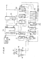
- Fig. 5 is a block diagram showing the first embodiment of the present invention;
- Fig. 6 is a block diagram for creating a crossover dot recording clock signal;
- Fig. 7 is an explanatory diagram of detection of the amounts of dot misregistration;
- Fig. 8 shows another block diagram for creating the crossover dot recording clock signal;
- Fig. 9 is a block diagram showing an example of a frequency divider/delay circuit;
- Fig. 10 is a signal waveform diagram showing the operation thereof;
- Fig. 11 illustrates a modification of the example shown in Fig. 8;
- Fig. 12 is an explanatory diagram showing the basic concept of correction according to a second embodiment of the present invention;
- Fig. 13 is a block diagram for generating dot recording clock signals responsive to rotational errors of a polygon mirror;
- Fig. 14 illustrates the relation between one dot and delayed clock signals;
- Fig. 15 is an explanatory diagram showing the manner of obtaining the scanning interval between a start sensor and an end sensor; and
- Fig. 16 illustrates the result of correction according to the present invention.
- With reference to Fig. 2, description is now set forth according to a first embodiment of the present invention. Fig. 2(A) shows a dot train formed on a standard scanning line with no dot misregistration and a dot recording clock signal for forming the dot train, on the assumption that one scanning line of standard scanning length L is formed by 12 dots (for convenience of illustration). On the other hand, Fig. 2(B) shows the case where the average rotational speed on a reflecting mirror surface is delayed by approximately 2.5% (1/40) with respect to the standard level, by a rotation error of a polygon mirror or the like and dot misregistration of (d/10) x 3 is caused at the terminating end of the scanning line. The start position of the scanning line is correct by employment of, e.g., the aforementioned second conventional method. Both of the cases of Figs. 2(A) and 2(B) require the same time for 12 cycles of the dot recording clock signals, whereas the scanning length in the said time is shorter than the standard scanning length L in the case of Fig. 2(B) as the result of delay in scanning speed. Symbol d denotes a standard dot diameter. Although the dot diameter is illustrated as equal to a dot interval, the dot diameter is generally larger than the dot interval for exposure/recording. The following description is made on the assumption that the dot diameter is equal to the dot interval. In the case of Fig. 2(B), dot misregistration of d/10 is caused every four dots of the dot train, and the dot misregistration at the 12-th dot in the terminating end of the scanning line is (d/10) x 3.
- Fig. 2(C) shows a case where crossover correction according to the present invention is performed in scanning of Fig. 2(B) to eliminate the dot misregistration. In order to perform such crossover correction, N dot recording clock signals φ₁ to φN are previously prepared in the present invention by equally dividing the period t of a reference dot recording clock signal φ₁ into N to delay the same by 1/N as shown in Fig. 3. Fig. 3 illustrates an example in the case of N = 10. As hereinafter described, time resolution adjustable by crossover correction of these dot recording clock signals φ₁ to φN is t/N, and length resolution is d/N (in case of standard scanning speed).
- Fig. 4 is an explanatory diagram showing crossover correction of the dot recording clock signals. In this case, crossover is performed from a dot recording clock signal φK within the N signals to a phase-lagging dot recording clock signal φK+1 adjacent to φK in timing as shown by an arrow in the figure, to obtain a crossover dot recording clock signal φX. In the cycle where crossover of the crossover dot recording clock signal φX is performed, the pulse time width is lengthened by t/N, whereby the dot diameter formed in the cycle is larger by d/N that the standard diameter. Thus, as compared with the scanning length only by the dot recording clock signal φK, the scanning length by the crossover dot recording clock signal φX obtained by crossover of φK to φK+1 is large by d/N. When crossover is performed toward a phase-leading side as φK to φK-1 to the contrary, the scanning length is shorter by d/N. Thus, the scanning length can be adjusted in a multiple of d/N by performing a plurality of times of crossover in a scanning interval for one scanning line.
- Referring again to Fig. 2, it is assumed that scanning causing the dot misregistration of Fig. 2(B) is performed in synchronization with φ₃ within previously prepared ten dot recording clock signals φ₁ to φ₁₀. In the crossover correction of the present invention shown in Fig. 2(C), operation is started from the dot recording clock signal φ₃ for performing crossover of the dot recording clock signals sequentially in the phase lag direction as φ₃ →φ₄ →φ₅ →φ₆ three times before completion of scanning in order to create the crossover dot recording clock signal φX, and thereby perform scanning synchronously with the same. Namely, adjustment is so performed that the scanning length is lengthened by d/10 per cycle of the crossover shown by arrows in the figure, whereby the dot misregistration of (d/10) x 3 caused in the case of Fig. 2(B) is completely eliminated at the terminating end of the scanning line. Further, adjustment of the dot misregistration is uniformly dispersed over one scanning line, whereby no unnaturalness is caused in the dot train thus obtained.
- Fig. 5 is a block diagram showing an embodiment of the present invention for performing the aforementioned crossover correction. Referring to Fig. 5, a
film feed roller 1 is rotatingly driven by asubscanning motor 2, whereby afilm 3 serving as a recording photosensitive material is fed in a subscanning direction shown by an arrow in the figure. Animage processing circuit 4 processes image signals obtained from an input apparatus or the like to output dot signals indicating variable density (including black and white) of respective dots to asemiconductor laser 5 in synchronization with crossover dot recording clock signals internally generated according to the described embodiment. Thesemiconductor laser 5 outputs a laser beam responsive to the dot signals as received. The laser beam divergently outputted from thesemiconductor laser 5 is changed into parallel beam by acollimator lens 6 and corrected by acylindrical lens 7, in order to be irradiated on reflecting mirror surfaces of ahexahedral polygon mirror 8. - The
polygon mirror 8 comprises a hexahedral rotation mirror for reflecting and deflecting the laser beam, to scan one line of a dot train by one reflecting mirror surface. The laser beam reflected and deflected by thepolygon mirror 8 is scanned in the main scanning direction on thefilm 3 through anfϑ lens 9 and acylindrical lens 10. Thefϑ lens 9 is adapted to obtain light collecting points in the same size regardless of positions of the laser beam on the scanning lines so that the spot of the collected light is moved by a certain distance when the polygon mirror is rotated by a certain angle, i.e., to enable scanning on the scanning lines at a constant speed. Thecylindrical lens 10 is adapted to perform straightening correction of the laser beams in a subscanning direction similarly to thecylindrical lens 7, which are adapted to compensate straightening errors of thepolygon mirror 8 in industrial processing. - A reflecting
mirror 11 and astart sensor 12 formed by an optical detector such as a photodiode are provided immediately in front of a main scanning start position in order to detect passage of the laser beam in advance of scanning one scanning line. A reflectingmirror 13 and anend sensor 14 similar to thestart sensor 12 are provided immediately at the back of a main scanning end position in order to detect passage of the laser beam after completion of scanning of one scanning line. Detection signals from thesensors image processing circuit 4. - Even if the start positions of respective scanning lines are registered or regularized by the
start sensor 12 as hereinabove described with reference to the second conventional method, dot misregistration can be caused by the rotational error of thepolygon mirror 8 at the terminating end of each scanning line as hereinabove described with reference to Fig. 2(B). The amount of possible dot misregistration at the terminating end of the scanning line is expressed as follows:
ΔY = L x J ...(1)
where symbol L indicates the scanning length and symbol J indicates a rotational error (speed regulation). Assuming that, for example, L = 200 mm for main-scanning a shorter edge of A4 size and J = 0.02 % as the rotational error of a commercially available polygon mirror, the amount of dot misregistration at the terminating end of the scanning line is expressed as follows:
ΔY = 200 x 0.0002 = 0.04 mm ...(2)
Assuming that recording resolution is 1270 lines/inch (diameter d of one dot = 20 µm), the ratio of the amount of dot misregistration to one dot is as follows:
ΔY/d = 0.04 / 0.02 = 2 ...(3)
When misregistration of two dots is caused, linear edges of a recorded image are irregularized to the point of being useless as a line original or a halftone plate. Picture quality is considerably deteriorated for images other than half tone plates. - In the embodiment shown in Fig. 5, therefore,
image processing circuit 4 generates N dot recording clock signals φ₁ to φN shown in Fig. 3 in synchronization with the detection output of the start sensor 12 (i.e., to regularize the start positions of the respective scanning lines) while creating the crossover dot recording clock signals φX obtained by starting operation from the selected dot recording clock signal in order to perform crossover correction by a number of times responsive to the amount of dot misregistration. Thus, the start positions of the respective scanning lines are registered or regularized and the dot misregistration at the terminating ends of the scanning lines can be substantially eliminated. - Fig. 6 is a block diagram showing an exemplary circuit for generating the aforementioned crossover dot recording clock signal φX in the
image processing circuit 4. A reference dot recording clock signal is generated by aclock generator 15 such as a crystal oscillator and passed through adelay circuit 16, to create the N dot recording clock signals φ₁ to φN by equally dividing the cycle t of the reference dot recording clock signal into N and delaying the same by t/N. Dot recording clock signals φ₁ to φN are employed for creating the crossover dot recording clock signal φX, as well as for detecting the amounts of dot misregistration on the respective reflecting mirror surfaces caused by rotational errors of thepolygon mirror 8, in this embodiment. As hereinabove described, the time resolution for detection of the dot misregistration amounts is t/N and the length resolution is d/N (d: dot diameter). With reference to a timing chart of Fig. 7, description is now made in detail on detection of dot misregistration. - As shown in Fig. 7, detection output of the
start sensor 12 is supplied to a clock input of alatch circuit 17, so that current states (1, 1, 0, 0, 0, 0, 0, 1, 1, 1 in Fig. 7) of the dot recording clock signals φ₁ to φN are latched in thelatch circuit 17. Anencoder 18 encodes the contents latched in thelatch circuit 17 to output a signal indicating a sequence number (3 of φ₃ in Fig. 7) of a dot recording clock signal synchronized with the detection output of the start sensor 12 (i.e., rising immediately after the detection output of thestart sensor 12 to become "1"). Encoding in theencoder 18 can be performed by identifying, for example, the first occurence of continuous "0" or "0" immediately after continuous "1". Output from theendoder 18 is supplied to afirst selector 19, which in turn selects the corresponding dot recording clock signal (φ₃ in case of Fig. 7), to output the same to athird counter 20. - The detection output of the
start sensor 12 is also supplied to a clock input of a D flip-flop 22 through anOR gate 21, whereby the Q output of the D flip-flop 22 rises to "1". This Q output is supplied to an enable terminal of thethird counter 20, which in turn is activated to count the selected dot recording clock signal (φ₃ in Fig. 7) in response to its leading edge. Thereafter, detection output of theend sensor 14 is supplied to the clock input of the D flip-flop 22 through theOR gate 21, whereby the Q output of the D flip-flop 22 falls to "0". Thus, thethird counter 20 is disabled and terminates counting. Fig. 7 shows the case where counting is performed up to 10002. This count value indicates the number of dots that can be recorded between the start sensor position and the end sensor position, whereas such number is not effective since the final one count does not correspond produce a whole dot (i.e., one cycle of the dot recording clock signal) as shown in Fig. 7. This count value is reformed in the manner as hereafter described. - A
subtracter 23 receive the count value to subtract a reference count value previously set in alatch circuit 24 through a CPU or the like from the count value. For example, the interval from the start sensor position to the end sensor position is mapped with the shorter edge side of 200 mm of the A4 size, to scan the same in a main scanning direction in resolution of the 1270 lines/inch (dot diameter = 20 µm). In this case, the standard dot number is:
200 ÷ 0.02 = 10000 (dots) ...(4)
whereas the final one count within the count value of thethird counter 20 is not effective as hereinabove described, therefore 10001, obtained by adding 1 to the standard dot number of 10000, is set in thelatch circuit 24 as a reference count value in order to exclude the final one count by subtraction. Therefore, the result of subtraction by thesubtracter 23 is:
10002 - 10001 = +1 ...(5)
Thus, it is evident that the amount of dot misregistration in the unit of dot is + 1 dot. The + sign means that the rotational speed at the reflecting surface of thepolygon mirror 8 is delayed as compared with the standard rotational speed, and therefore the scanning length of one scanning line is shorter than the standard scanning length (terminating end of one scanning line is immediately ahead of 10001-th count). - On the other hand, the following processing is performed in order to detect the amount of dot misregistration smaller than one dot by time resolution of t/N (length resolution of d/N in standard rotational speed): The current states of the dot recording clock signals φ₁ to φN are latched in a
latch circuit 25 in response to detection output of theend sensor 14 to encode the same by anencoder 26 in order to derive a sequence number (i.e., 9 in Fig. 7) of a dot recording clock signal (φ₉ in Fig. 7) synchronous with the detection output of theend sensor 14. This operation is similar to that in the aforementioned case of deriving the sequence number of the dot recording clock signal synchronous with the detection output of thestart sensor 12 by thelatch circuit 17 and theencoder 18. Asubtracter 27 receives the outputs from theencoders encoder 18 from that of theencoder 26. In the example shown in Fig. 7, the result is:
9 - 3 = +6 ...(6)
Thus, it is evident that the amount of dot misregistration smaller than one dot is (d/10) x 6. When the result of subtraction in thesubtracter 27 is negative, a number N (10 in Fig. 7) is added to the negative result of subtraction in a translation table 28 (of a subsequent stage) to process the result as a positive value. Assuming that, for example, the detection output of theend sensor 14 is generated as the timing shown by the one-dot chain line, the dot recording clock signal synchronous with this is φ₁ and the result of subtracting thesubtracter 27 is 1 - 3 = -2, while the translation table 28 changes the result into 10 - 2 = 8, in order to perform processing on the assumption that the amount of dot misregistration smaller than one dot is (d/10) x 8. - The amounts of dot misregistration thus resulting, i.e., the results of subtraction in the
subtracters - For example, the manner of obtaining the table data in the case where N is 10 and the standard dot number of one scanning line is 10000 is as follows:
- (1) When the result of subtraction in the
subtracter 23 is +1 and thesubtracter 27 is +6: - The total amount of dot misregistration in this case is (d/10) x 16 since 10 x 1 + 6 = 16, therefore, crossover of the dot recording clock signals may be performed 16 times. In order to uniformly perform a crossover of 16 times during one scanning (i.e., 10000 dots), crossover must be performed every 10000/17 dots. Since the result of subtraction in the
subtracter 23 is positive and the scanning length of one scanning line is shorter than the standard value as hereinabove described, the crossover phase direction is that of phase lag. - (2) When the result of subtraction in the
subtracter 23 is -2 and that in thesubtracter 27 is -3: - As hereinabove described, -3 is processed as 7. The total amount of dot misregistration is (d/10) x 13 since 10 (-2) + 7 = -13, whereby crossover may be performed every 10000/14 dots for the reson described in the item (1). Since the result of subtraction in the
subtracter 23 is negative and the scanning length of one scanning line is longer than the standard value, the crossover phase direction is that of phase lead. - Symbols of the table data created on the basis of the above are shown as follows: (Symbol INT indicates integral parts and symbols U and D indicate crossover phase directions of phase lag and phase lead respectively.

- When there is no error, a value causing no carry, e.g., INT(10000/1) + 1 = 10001 is loaded in a
first counter 30. Then, no crossover takes place since the output of asecond counter 31 remains at zero. - The data of the crossover timing and the crossover phase direction thus obtained are inputted in a
shift register 29 and applied to the same reflecting mirror surface of thepolygon mirror 8 after one rotation. Theshift register 29 then shifts the data in response to a detection output of thestart sensor 12, i.e., every 1/6 rotation of thepolygon mirror 8, in order to supply the data to thefirst counter 30 upon one rotation of thepolygon mirror 8. It is well known that there is considerable regularity concerning rotational error(s) of each surface of a general polygon mirror, and hence no new errors are introduced even if correction is performed by employing error data of a preceding mirror rotation. - Further operation is described with reference to Fig. 2, on the assumption that INT (12/4) = 3 as obtained from the crossover timing and U (lag) is obtained as the crossover phase direction. (This assumption is made in order to facilitate easy understanding of the present invention.) When there is detection output from the
start sensor 12 with respect to the same reflecting mirror surface of thepolygon mirror 8 after one rotation from the time when the above data was generated, crossover timing = 3 is preset in thefirst counter 30 from theshift register 29, while the data of crossover phase direction = U (lag) is preset in thesecond counter 31 from theshift register 29. At the same time, the sequence number of the dot recording clock signal synchronous with the detection output of thestart sensor 12 is detected by thelatch circuit 17 and theencoder 18, as hereinafter described. The following description is made on the assumption that the dot recording clock signal synchronous with the detection output of thestart sensor 12 is φ₃ and the sequence number = 3 is obtained from theencoder 18. - The
counter 31 is reset in a blanking interval from the detection output of theend sensor 14 to precede scanning the detection output of thestart sensor 12 of the current scanning, and hence the count output of thesecond counter 31 is zero at the beginning. The D flip-flop 22 and thethird counter 20 are similarly reset in the blanking interval. On the other hand, aload value 3 is loaded in thefirst counter 30 upon receipt of the detection output from thestart sensor 12. Immediately after the detection output of thestart sensor 15, therefore, anadder 32 receivesvalue 3 from theencoder 18 and value zero from thesecond counter 31, and also supplies thevalue 3 to asecond selector 33. Thesecond selector 33 responsively selects φ₃ from the dot recording clock signals φ₃ to φN and outputs the crossover dot recording clock signal φX. This crossover dot recording clock signal φX is supplied to clock inputs of the first andsecond counters second counter 31 is connected to the carry output of thefirst counter 30 and therefor thesecond counter 31 is disabled until occurrence of the carry output; hence counting is first performed only by thefirst counter 30. - The
first counter 30 down-counts one by one from the aforementionedpreset value 3 for every leading edge of the crossover dot recording clock signal φX. The carry output of thefirst counter 30 rises when the count value reaches 1, whereby thesecond counter 31 is activated. In response to a subsequent leading edge of the crossover dot recording clock signal φX. The carry output of thefirst counter 30 rises when the count value reaches 1, whereby thesecond counter 31 is activated. In response to a subsequent leading edge of the crossover dot recording clock signal φX, thesecond counter 31 up-counts by one from zero, whereby the count value becomes 1. The instruction for the up-counting is supplied by the aforementioned preset data of crossover phase direction = U (lag). If the crossover phase direction = D (lead), down-counting is performed so that the count value becomes -1. The carry output of thefirst counter 30 falls at the same time when the count value of thesecond counter 31 becomes 1, whereby thesecond counter 31 is again disabled, and thepreset value 3 is loaded in thefirst counter 30 on the trailing edge thereof. - When the count value of the
second counter 31 is 1, theadder 32 receives 3 and 1, and therefore the added output resulting thereof is 4. Thesecond selector 33 responsively selects the dot recording clock signal φ₄ to output the same as the crossover dot recording signal φX. Thus, crossover of adjacent dot recording clock signals in the phase lag direction is performed. - Similar cycles of operation are repeated in order to create the crossover dot recording clock signal φX subjected to crossover in uniform intervals of φ₃ → φ₄ → φ₅ → φ₆ every three cycles (i.e., three dots) of the crossover dot recording clock signal φX. The dot misregistration in Fig. 2(B) is eliminated by scanning in synchronization with the crossover dot recording clock signal φX, as hereinabove described. Although the 13-th dot is a dot recording clock signal φ₇, no influence is exerted by the same since scanning of one scanning line is completed by 12 dots.
- Fig. 8 is a block diagram showing a modification of the circuit for creating the crossover dot recording clock signal φX in the
image processing circuit 4. In this modification, aclock generator 15 generates a clock signal φORG of a frequency N times the dot recording clock signals φ₁ to φN (i.e., cycle t/N) to be frequency-divided and delayed by a frequency divider/delay circuit 34, in order to create N dot recording clock signals φ₁ to φN. - Fig. 9 is a block diagram showing an example of the frequency divider/
delay circuit 34. The clock signal φORG from theclock generator 15 is frequency-divided into 1/N by afrequency dividing counter 35. The clock signal thus frequency- divided into 1/N is input to D₁ input of a D flip-flop 31, to be outputted as a dot recording clock signal φ₁ in response to the leading edge of the clock signal φORG. The dot recording clock signal φ₁ is also input to D₂ input of the D flip-flop 36, to be outputted as a dot recording clock signal φ₂ in response to a subsequent leading edge of the clock signal φORG. Thus, N dot recording clock signals φ₁ to φN delayed by the cycle t/N of the clock signal φORG can be generated. (Fig. 10 illustrates this situation.) - In the modification shown in Fig. 8, the
third counter 20 receives the clock signal φORG at its clock input and is activated only during the interval between the detection output of thestart sensor 12 and that of theend sensor 14 to count the clock signal φORG, as hereinabove described with reference to the embodiment of Fig. 5. This count value is latched in alatch circuit 37 in synchronization with the detection output of theend sensor 14. Since the cycle of the clock signal φORG is t/N, the count value of thethird counter 20 is a count value by a time resolution of t/N (length resolution in standard rotational speed of thepolygon mirror 8 is d/N). Therefore, if there is no dot misregistration when the standard dot number of one scanning line is 10000 for example, the count value of thethird counter 20 is 10000 x N. In other words, 10000 x N is processed as a reference count value, so that difference between this reference count value and the count value of thethird counter 20 indicates the amount of dot misregistration by the length resolution of d/N. - The translation table 28 receives the count value of the
third counter 20 latched in thelatch circuit 37 and outputs data for crossover timing and crossover phase direction required to eliminate the amount of dot misregistration expressed by the count value. The concept of creation of table data is similar to that in the embodiment of Fig. 6, and examples of the dot number of one scanning line is equal to 10000 and N is equal to 10 are as follows:
first counter 30, similar to the embodiment of Fig. 6. - This data is supplied to the
shift register 29, so that the crossover dot recording clock signal φX is generated similarly to the embodiment of Fig. 6. Then, scanning is performed without dot misregistration by the crossover dot recording signal. - Although crossover for 16 times is performed every 10000/17 dots during scanning when the result of subtraction in the
subtracters shift register 29 by the translation table 28 as a result of subtraction. The first data 10000/32 is loaded in thefirst counter 30 at the beginning and the second data 10000/16 is loaded in thefirst counter 30 when a carry is caused from thefirst counter 30 after starting of recording. When the result of subtraction by the subtractors 23 and 27 is within ± 1, both the first and second data are identical to those as hereinabove described. This also applies to the modification shown in Fig. 8. - Figs. 11(A) and 11(B) shows a modification of this case. The translation table 28 transfers U/D signal and two types of load values to the
shift register 29 as hereinabove described with reference to Fig. 6, on the basis of the result in thesubtracters timing circuit 50 goes low at timing shown in Fig. 11(B), and thefirst counter 30 fetches first data (INT(10000/32)) at the timing of φX during this interval. The output Q₂ of thetiming circuit 50 goes high when φX continues, and second data (INT(10000/16)) is transferred as the load value to thefirst counter 30. When counting by thefirst counter 30 continues so that thefirst counter 30 causes a carry, the second data is loaded in thefirst counter 30. Thereafter the output Q₂ of thetiming circuit 50 holds the high level, whereby the second data is loaded very time a carry occurs. - Although crossover in each of the aforementioned embodiments, and modifications are performed toward adjacent phases, such crossovers may be performed toward adjacent phases, such crossovers may be perfomed when a phase is excessive by one and remain within a range where the picture quality is not deteriorated. The amount of crossover is reduced by the excess, as a matter of course.
- According to the first embodiment of the present invention as hereinafter described, dot misregistration on the scanning lines caused by rotational errors of the polygon mirror can be easily eliminated with simple structure without providing grating or synchronous control circuitry and without requiring a polygon mirror of high accuracy.
- With reference to Fig. 12, description is now made on the basic concept of a second embodiment of the present invention. First, assume the start positions of respective scanning lines are registered by the
start sensor 12 as hereinabove described with reference to the second conventional method, for example, dot misregistration is caused by rotational error of thepolygon mirror 8 at the terminating end of each scanning line as shown in Fig. 12(a). Referring to Fig. 12, symbols S and E denote correct start and end positions (dot center positions) of the scanning lines. The amount ΔY of dot misregistration at the terminating end of the scanning line is expressed as follows:
ΔY = L x J ...(7)
where symbol L indicates scanning length and symbol J indicates rotational error (speed regulation). When L = 100 mm and J = 0.01 %, for example, the amount of dot misregistration at the terminating end of the scanning line is
ΔY = 100 x 0.0001 = 0. 01 mm ...(8)
Assuming that recording resolution is 1270 lines/inch (diameter d of one dot = 20 µm), the ratio of the amount of dot misregistration to one dot is:
ΔY/d = 0.01 / 0.02 = 1/2 ...(9)
Fig. 12(a) shows the case of dot misregistration of 1/2 dot, whose recorded image edges are non-linear and indented. This image cannot be employed for a line original or a halftone plate. - The second embodiment of the present invention reduces dot misregistration by compensating for approximately one half of the dot misegistration caused at the terminating end of the scanning line in a starting point of scanning. For example, the terminating end of the second scanning line shown in Fig. 12(a) is leftwardly misregistered by 1/4 dot, and hence the same is rightwardly displaced by half the amount of misregistration ,i.e., 1/8 dot from the scanning start position as shown in Fig. 12(b). The terminating end of the third scanning line in Fig. 12(a) is rightwardly misregistered by 1/4 dot, and hence the same is leftwardly displaced by half the amount of misregistration, i.e. 1/8 dot from the scanning start position as shown in Fig. 12(b). The scanning start positions are misaligned by this operation, whereas it is obvious that the total amount of dot misregistration is reduced to a half, i.e., 1/4 dot. According to this method, the amounts of dot misregistration at the terminating ends of the scanning lines are suppressed to about half that of the prior art at the maximum, while the same are dispersed over the entire screen (particularly in the vicinity of both ends) thereby reducing the amount of dot misregistration as a whole. Such an effect is increased as dot resolution is increased and rotational error accuracy of the polygon mirror is improved, so that apparent picture quality is improved.
- In order to implement the aforementioned concept, the embodiment obtains the rotational error times of respective surfaces of the polygon mirror and performs image recording by dot recording clock signals out of phase by about half the error time of each surface of the mirror having a rotational error. The structure shown in Fig. 5 may be employed, and in this case, the
image processing circuit 4 receiving the detection signals from thestart sensor 12 and theend sensor 14 obtains the rotational error time of each surface of thepolygon mirror 8, in order to output a dot signal indicating variable density of each dot to thesemiconductor laser 5, for every surface of thepolygon mirror 8, in synchronization with a dot recording clock signal responsive to the obtained rotational error of each surface of the mirror. - Fig. 13 is a block diagram showing circuitry of the
image processing circuit 4 for generating the dot recording clock signals responsive to the rotational errors of the respective surfaces of thepolygon mirror 8. Acrystal oscillator 15 generates a reference clock signal, which is passed through adelay circuit 16 so that the cycle t of the reference clock signal is equally divided into N to create N clock signals delayed by t/N. The N clock signals are numbered from 1 to N in sequence from the reference clock signal. Fig. 14 illustrates the case of N = 10. Time resolution measurable by employment of the N clock signals is t/N, and length resolution is d/N (assuming that the diameter of one dot is d). - According to the embodiment hereafter described in detail, the aforementioned N clock signals are used to obtain the rotational error factor of the respective reflecting mirror surfaces of the
polygon mirror 8 while selecting a clock signal, from the N signals, which is out of phase by 1/2 of the obtained rotational error times with respect to a clock signal synchronous with detection output of thestart sensor 12, to employ the same as a dot recording clock signal. - First, a clock signal synchronous with the detection output of the
start sensor 12 is selected form φ₁ to φN in a circuit formed by a J-K flip-flop 17, adelay circuit 18, a D flip-flop 19, adecoder 20 and aselector 21. The operation is as follows: - The J-K flip-
flop 17 is reset in a blanking interval preceding scanning and current scanning; for example, to enter a set standby state by receiving the detecting output of thestart sensor 12 in its J input. Thereafter, Q output corresponding to a first inputted signal of clock signal φ₁ to φN becomes "1", and the current state of the Q output is latched in the D flip-flop 19 by clocking the D flip-flop 19 by a signal generated by delaying the detection output of thestart sensor 12 through adelay circuit 18. Thedecoder 20 decodes the Q output of the D flip-flop 19, and outputs a signal CKS (CKS = 1 to N) representing the number of the clock signal synchronous with the detection output of thestart sensor 12, Theselector 21 then selects a clock signal φ(CKS) corresponding to CKS from the N clock signals φ₁ to φN. Fig. 15 shows an example in which a clock signal of No. 3 (CKS = 3) is selected in response to the detection output of thestart sensor 12. - On the other hand, a circuit part formed by a J-K flip-
flop 22, adelay circuit 23, D flip-flop 24 and adecoder 25 obtains a signal CKE (CKE = 1 to N) representing the number of a clock signal synchronous with the detection output of theend sensor 14. This operation is similar to that for obtaining CKS as hereinabove described, and hence description thereof is omitted. Fig. 15 shows an example where a clock signal of No. 9 (CKS = 9) is selected in response to the detection output of theend sensor 14. - The clock signal φ(CKS) selected by the
selector 21 is counted by acounter 26 until detection output of theend sensor 14 is generated. Assuming that COUNT(CKS) represents the count number, the scanning time between thestart sensor 12 and theend sensor 14 is generated from the same and the aforementioned CKS and CKE, as follows:
When CKS ≦ CKE,
T = COUNT(CKS) x t + (CKE - CKS) x t/N ...(10)
when CKS > CKE,
T = (COUNT(CKS) + 1) x t - (CKS - CKE) x t/N
= COUNT(CKS) x t + (N + CKE - CKS) x t/N ...(11) - When the time resolution t/N by the N clock signals is normalized to 1, i.e., when the scanning time is the same in resolution of the numbering of the clock signals, the count value CT of the scanning time can be expressed as follows:
When CKS ≦ CKE,
CT = T x N/t = COUNT(CKS) x N + CKE - CKS ...(12)
When CKS> CKE,
CT = T x N/t = COUNT(CKS) x N + N + CKE - CKS ...(13) - In the example shown in Fig. 15, COUNT(CKS) = 5, CKE - CKS = 6 and N = 10, and CT = 56 from the above expression (12).
- In the embodiment shown in Fig. 13, circuitry for generating the above expressions (12) and (13) comprises a
multiplier 27, asubtracter 28, anadder 29, aselector 30 and anadder 31. Themultiplier 27 multiplies COUNT(CKS) outputted from thecounter 26 by N, to generate the first terms of the expressions (12) and (13). Thesubtracter 28 receives the output of thedecoder 25, i.e., CKE in its subtracted input while receiving the output of thedecoder 20, i.e., CKS in its subtacting input and operates CKE - CKS thereby and outputs the result to theadder 29 and theselector 30, and outputs a sign indicating negative/positive value of the result of operation to theselector 30. Theadder 29 performs adding N, to output N + CKE - CKS to theselector 30. Theselector 30 selects CKE - CKS, i.e., the result of thesubtracter 28 when the result of thesubtacter 28 is positive or zero, i.e., when CKS ≦ CKE to output the same, while selecting N + CKE - CKS, i.e., the result of theadder 29 when CKS > CKE to output the same. Theaddder 31 adds up the output of themultiplier 27 and that of theselector 30, thereby obtaining the scanning time count value CT by the aforementioned expressions (12) and (13). - The scanning time count value CT is compared with a standard count value CTN, to recognize rotation error times of the respective surfaces of the
polygon mirror 8. In this embodiment, an average value CTAVE of six scanning time count values CT obtained by one rotation of thepolygon mirror 8 is employed as the standard count value CTN. Assuming that the obtained scanning time count values CT are CT₁, CT₂, ..., CT₆ in sequence,
CTAVE = (CT₁ + ... + CT₆) / 6 ...(14)
In general, M (M: integral multiple of the surface number of the polygon mirror 8) of CTj corresponding to an arbitrary rotation number of thepolygon mirror 8 can be averaged so that:
polygon mirror 8, and assuming that the count values of the rotational error times are expressed by CRj,
CRj = CTj - CTAVE ...(16) - In the embodiment shown in Fig. 13, circuitry for generating the expressions (14) and (16) comprises a
shift register 32, a summingcircuit 33, adivider 34 and asubtracter 35. Theshift register 32 receives CTj as the results of operation of theadder 31 and stores six of the same while shifting the same, and the shifted Cj are supplied to the subtracted input of thesubtracter 35. The summingcircuit 33 sums up the continuous six CTj stored in theshift register 32, so that CTAVE of the expression (14) is obtained by dividing the same into 1/6 by thedivider 34. The CTAVE is supplied to the subtracting input of thesubtracter 35, which in turn generates CTj - CTAVE of the expression (16). Thus, the count values CRj of the rotational error times of thepolygon mirror 8 are obtained. - The count value CRj corresponds to the corresponding surface in the preceding rotation of the
polygon mirror 8, and it is well known that there is considerable regularity with respect to rotational error(s) of each surface in general rotation of a polygon mirror, whereby no new error(s) is introduced by employing the data of rotational error times of a preceding rotation. - If CRj > 0, the scanning time between the
start sensor 12 and theend sensor 14 is no longer than the standard value (i.e., rotation of thepolygon mirror 8 is delayed), and the scanning length for one scanning line recording is shorter than the standard level, as shown in the second line in Fig. 12(a). When CRj < 0, on the other hand, the scanning length for one scanning line recording is longer than the standard level, as shown in the third line of Fig. 12(a). Therefore, the direction for reducing the dot misregistration caused by rotational errors of thepolygon mirror 8 is rightward direction (in Fig. 13) i.e., phase shift in a positive direction in dot recording clock signal when CRj > 0 , while the phase shift is to negative contrary when CRj < 0. - Assuming that CKH represents the count value of phase correction for finding a clock signal phase-shifted in a direction for reducing the dot misregistration caused by error by 1/2 of the rotational error time of the
polygon mirror 8, the following expression holds:
CKH = 1 / 2 · CRj ...(17)
Therefore, an identification number CKV for a clock signal to be selected as the dot recording clock signal (one of φ₁ to φN is obtained by the following expression:
CKV = (N + CKS + CKH) mod N ...(18)
N is added for operation in situations where the value of CKS + CKH is negative, while the remainder in the division by N is obtained since assumed is such case where the amount of dot misregistration is within one dot. - In the embodiment shown in Fig. 13, circuitry for generating the above expressions (17) and (18) comprises a
divider 36, a summingcircuit 37 and aROM 38. Thedivider 36 divides CRj outputted from thesubtracter 35 by 1/2 to generate CKH of the expression (17), and outputs the same to the summingcircuit 37. The summingcircuit 37 receives CKH, CKS outputted from thedecoder 20 and the constant N and sums up the same to generate N + CKS + CKH. On the other hand, the result of operation of (N + CKS + CKH)modN in the expression (18) is written in a look-up table in theROM 38, which in turn receives output from the summingcircuit 37, to read corresponding CKV. - The CKV thus obtained is input to a
selector 39, which in turn outputs a clock signal φ(CKV) corresponding to CKV from the N clock signals φ₁ to φN as the dot recording clock signal. The image processing circuit of Fig. 13 outputs a dot signal representing variable density of each dot in synchronization with the dot recording clock signal φ(CKV) is thus input to thesemiconductor laser 5. Thus, as shown by dotted lines in Fig. 16, the scanning lines causing dot misregistration are entirely shifted by half the amounts of misregistration, thereby reducing the total amount of dot misregistration. Referring to Fig. 16, dot misregistration of (1/2) · d is corrected by the present invention so that the amount of total dot misregistration is reduced to (1/4) · d. The dot misregistration is substantially zero at the center of the screen. The present invention is applicable to both on-off modulation and continuous modulation. - According to the second embodiment as hereinabove described, dot misregistration of scanning lines caused by rotational errors of a polygon mirror can be easily reduced with simple structure without providing grating or synchronous control circuitry and without requiring extremely accurate polygon mirrors. Further, the dot misregistration is substantially zero at the center of the screen.
- Although the present invention has been described and illustrated in detail, it is to be clearly understood that the same is by way of illustration and example only and is not to be taken by way of limitation, the spirit and scope of the present invention being limited only by the terms of the appended claims.
Claims (16)
generating N dot recording clock signals by delaying a dot recording clock signal of a cycle t by t/N;
detecting said recording beam by a start sensor in advance to scanning one scanning line;
detecting passage of said recording beam after completion of scanning one scanning line by an end sensor;
counting an interval between detection times when said beam impinges on said start and end sensors with a time resolution of t/N for each surface of said polygon mirror to obtain a difference between a counted value and a prescribed reference count value as a number of clock crossover times with a sign of said difference as a crossover phase direction;
selecting one of said N dot recording clock signals in synchronization with detection output of said start sensor for each surface of said polygon mirror;
generating a crossover dot recording clock signal by performing crossover correction from said selected dot recording clock signal sequentially to a dot recording clock signal adjacent in phase to said selected dot recording clock signal by said number of clock crossover times in said crossover phase direction; and
performing image recording by said crossover dot recording clock signal.
storing said number of clock crossover times and said crossover phase direction obtained; and
generating said crossover dot recording clock signal on the basis of storing said number of clock crossover times and said crossover phase direction after one rotation of said polygon mirror.
counting a first one of said N dot recording clock signals selected in synchronization with said detection output of said start sensor until a detection output is generated by said end sensor to obtain the count difference between said counted value and a prescribed reference count value; and
obtaining a sequence number difference between a second one of said N dot recording clock signals selected in synchronization with said detection output of said end sensor and said first dot recording clock signal to obtain said number of clock crossover times and said crossover phase direction on the basis of said count difference and said sequence number difference.
frequency-dividing a clock signal having a frequency N times that of said dot recording clock signal into 1/N while shifting said dot recording clock signal cycle by cycle to create N dot recording clock signals; and
counting said clock signal having said frequency of N times during the interval between said detection of outputs of said start sensor and said end sensor to obtain said number of clock crossover times and said crossover phase direction on the basis of the difference between the counted value and a reference count value and a sign of said difference.
detecting said recording beam by a start sensor in advance to scanning of one scanning line;
detecting passage of said recording beam after completion of scanning of one scanning line by an end sensor;
generating rotational error times for respective surfaces of said polygon mirror by obtaining a difference between a detection time interval when said recording beam impinges on said start and end sensors for each surface of said polygon mirror and a reference time interval;
generating a dot recording clock signal phase-shifted in a direction for reducing dot misregistration caused by said error by approximately one-half said error time for each surface of said polygon mirror; and
performing image recording by said generated dot recording clock signal.
said reference time interval corresponds to an average value of the detection time intervals between said start sensor and said end sensor with respect to respective surfaces of said polygon mirror.
creating N dot recording clock signals by delaying a dot recording clock signal of a cycle t by t/N;
obtaining rotation error times for respective surfaces of said polygon mirror by counting detection time intervals between said start sensor and said end sensor with a time resolution of t/N through said dot recording clock signals; and
selecting a dot recording clock signal phase-shifted in a direction for reducing dot misregistration caused by said error by approximately one-half said error time for each surface of said polygon mirror from said N dot recording clock signals to perform image recording thereby.
storing said rotational error times of respective surfaces of said polygon mirror as obtained; and
generating said dot recording clock signal on the basis of a corresponding one of said stored rotational error times while scanning by the same surface after one rotation of said polygon mirror.
means for generating N dot recording clock signals by equally dividing a cycle t of said dot recording clock signal and delaying said dot recording clock signal by t/N;
a start sensor for detecting passage of said recording beam in advance to scanning of one scanning line;
an end sensor for detecting passage of said recording beam after completion of scanning of one scanning line;
means for counting an interval between detection times when said beam crosses said start and end sensors in a time resolution of t/N for each surface of said polygon mirror thereby to obtain a number of clock crossover times and a crossover phase direction from a difference between a counted value and a reference count value and a sign of said difference, respectively;
means for selecting one of said N dot recording clock signals in synchronization with a detection output of said start sensor for each surface of said polygon mirror;
means for performing crossover from said selected dot recording clock signal in said crossover phase direction sequentially to adjacent dot recording clock signals by said number of clock crossover times to thereby create a crossover dot recording clock signal; and
means for performing image recording by said created crossover dot recording clock signal.
means for storing said number of clock crossover times and said crossover phase direction as obtained; and
means for obtaining said crossover dot recording clock signal on the basis of said stored number of clock crossover times and said crossover phase direction of scanning by the same surface after one rotation of said polygon mirror.
means for counting a first one of said N dot recording clock signals selected in synchronization with detection output of said start sensor until detection output is generated by said end sensor thereby to obtain the count difference between said counted value and a prescribed reference counted value; and
means for obtaining a sequence number difference between a second one of said N dot recording clock signals selected in synchronization with detection output of said end sensor and said first dot recording clock signal to thereby obtain said number of clock crossover times and said crossover phase direction on the basis of said count difference and said sequence number difference.
means for creating N dot recording clock signals by frequency-dividing a clock signal having a frequency N times that of said dot recording clock signal into 1/N wile shifting the said dot recording clock signal cycle by cycle; and
means for counting said clock signal of said frequency of N times in the interval between said detection output of said start sensor and that of said end sensor thereby to obtain said number of clock crossover times and said crossover phase direction on the basis of the difference between said count value and a reference count value and a sign of said difference.
a start sensor for detecting said recording beam in advance to scanning of one scanning line;
an end sensor for detecting passage of said recording beam after completion of scanning of one scanning line;
means for generating rotational error times for respective surfaces of said polygon mirror by obtaining a difference between an interval between detection times of said start and end sensors with respect to each surface of said polygon mirror and a prescribed reference time interval;
means for generating a dot recording clock signal phase- shifted in a direction for reducing misregistration caused by said error by approximately one-half said error time for each surface of said polygon mirror; and
means for performing image recording by said generated dot recording clock signal.
said reference time interval corresponds to an average value of detection time intervals between said start sensor and said end sensor with respect to respective surfaces of said polygon mirror.
means for creating N dot recording clock signals by delaying a dot recording clock signal of a cycle t by t/N;
means for generating rotational error times for respective surfaces of said polygon mirror by counting detection time intervals between said start sensor and said end sensor through said dot recording clock signals in a time resolution of t/N; and
means for selecting a dot recording clock signal phase-shifted in a direction for reducing dot misregistration caused by said error by approximately one-half said error time for each surface of said polygon mirror from said N dot recording clock signals perform image recording thereby.
means for storing said rotational error times for respective surfaces of said polygon mirror; and
means for generating said dot recording clock signal on the basis of a corresponding one of said stored rotational error times in scanning by the same surface after one rotation of said polygon mirror.
Applications Claiming Priority (4)
| Application Number | Priority Date | Filing Date | Title |
|---|---|---|---|
| JP61257727A JPH0668576B2 (en) | 1986-10-29 | 1986-10-29 | Jitter correction device for polygon mirror |
| JP257727/86 | 1986-10-29 | ||
| JP61279288A JPS63132214A (en) | 1986-11-21 | 1986-11-21 | Method and device for correcting jitter of polygon mirror |
| JP279288/86 | 1986-11-21 |
Publications (3)
| Publication Number | Publication Date |
|---|---|
| EP0265845A2 true EP0265845A2 (en) | 1988-05-04 |
| EP0265845A3 EP0265845A3 (en) | 1990-02-07 |
| EP0265845B1 EP0265845B1 (en) | 1993-09-22 |
Family
ID=26543370
Family Applications (1)
| Application Number | Title | Priority Date | Filing Date |
|---|---|---|---|
| EP87115501A Expired - Lifetime EP0265845B1 (en) | 1986-10-29 | 1987-10-22 | Method of and apparatus for jitter correction of a polygon mirror in an image recording apparatus |
Country Status (3)
| Country | Link |
|---|---|
| US (2) | US4872065A (en) |
| EP (1) | EP0265845B1 (en) |
| DE (1) | DE3787504T2 (en) |
Cited By (3)
| Publication number | Priority date | Publication date | Assignee | Title |
|---|---|---|---|---|
| EP0357190A2 (en) * | 1988-08-30 | 1990-03-07 | Kabushiki Kaisha TEC | Optical scanner |
| EP0605131A1 (en) * | 1992-12-29 | 1994-07-06 | Xerox Corporation | Method and apparatus for eliminating distortion via overscanned illumination for optical printers and the like having high gamma photosensitive recording media and high addressability |
| WO2010032862A1 (en) | 2008-09-16 | 2010-03-25 | Ricoh Company, Limited | Pixel clock generator and image forming apparatus |
Families Citing this family (26)
| Publication number | Priority date | Publication date | Assignee | Title |
|---|---|---|---|---|
| JPH0353212A (en) * | 1989-07-21 | 1991-03-07 | Minolta Camera Co Ltd | Light beam scanner |
| JP2937361B2 (en) * | 1989-09-29 | 1999-08-23 | 日本電気株式会社 | Laser processing machine |
| US5164843A (en) * | 1990-06-18 | 1992-11-17 | Olive Tree Technology, Inc. | Scanner with a linearized vco pixel clock |
| US5323183A (en) * | 1990-11-13 | 1994-06-21 | Canon Kabushiki Kaisha | Image recording apparatus |
| US5212570A (en) * | 1991-06-27 | 1993-05-18 | Xerox Corporation | Pixel clock phase locked loop for a laser scanner |
| JP3008225B2 (en) * | 1991-11-12 | 2000-02-14 | 富士写真フイルム株式会社 | Image recording device |
| US5477330A (en) * | 1992-10-16 | 1995-12-19 | Printware, Inc. | Synchronization to a start-of-scan detection, and digital generation of variable frequencies, from a fixed-frequency fixed-phase frequency source in an image generator in order to highly accurately time the placement of pixels upon a scan line |
| US5539441A (en) * | 1993-11-09 | 1996-07-23 | Xerox Corporation | Jitter reduction in an overfilled raster output polygon scanner system |
| JPH09281418A (en) * | 1996-04-11 | 1997-10-31 | Minolta Co Ltd | Image forming device |
| US6100915A (en) * | 1996-08-28 | 2000-08-08 | Asahi Kogaku Kogyo Kabushiki Kaisha | Laser drawing apparatus |
| JPH10260663A (en) * | 1997-01-14 | 1998-09-29 | Toshiba Corp | Jitter correcting circuit and plane display device |
| US6477656B1 (en) * | 1998-09-29 | 2002-11-05 | Konica Corporation | System for generating clock pulse which the number of pulses outputted within a predetermined time period is based on the number of calculated delay stages |
| US6219085B1 (en) * | 1998-10-21 | 2001-04-17 | International Business Machines Corporation | Method and system for improved performance of adjustable printer clocks in an electrophotographic device |
| JP3975626B2 (en) * | 1999-11-11 | 2007-09-12 | 株式会社オーク製作所 | Laser drawing device |
| US6549225B2 (en) * | 2001-02-28 | 2003-04-15 | Lexmark International, Inc. | Method of margin alignment and plane-to-plane registration in a tandem color electrophotographic machine |
| JP2002278408A (en) * | 2001-03-22 | 2002-09-27 | Konica Corp | Clock generating circuit and image forming device |
| US7271824B2 (en) * | 2001-09-28 | 2007-09-18 | Ricoh Company, Ltd. | Pixel clock generating apparatus, optical writing apparatus using a pixel clock, imaging apparatus, and method for generating pixel clocks |
| US7256815B2 (en) * | 2001-12-20 | 2007-08-14 | Ricoh Company, Ltd. | Image forming method, image forming apparatus, optical scan device, and image forming apparatus using the same |
| JP2003300341A (en) * | 2002-04-10 | 2003-10-21 | Ricoh Co Ltd | Pixel clock generating device, laser scanning device, and image forming apparatus |
| JP4593884B2 (en) * | 2002-05-10 | 2010-12-08 | キヤノン株式会社 | Laser scanning control device |
| US6933957B2 (en) * | 2002-09-24 | 2005-08-23 | Ricoh Company, Ltd. | Pixel clock generation apparatus, pixel clock generation method, and image forming apparatus capable of correcting main scan dot position shift with a high degree of accuracy |
| JP2006047590A (en) * | 2004-08-03 | 2006-02-16 | Sumitomo Precision Prod Co Ltd | Jitter measuring method, jitter measuring device, and image forming apparatus |
| JP5593749B2 (en) * | 2010-03-11 | 2014-09-24 | 株式会社リコー | Pixel clock generation apparatus and image forming apparatus |
| US8624949B2 (en) | 2011-03-29 | 2014-01-07 | Xerox Corporation | Raster output scanner with beam delay compensation to counteract jitter and wiper-induced banding |
| JP5947529B2 (en) * | 2011-12-05 | 2016-07-06 | キヤノン株式会社 | Image forming apparatus |
| US9327515B2 (en) | 2011-12-07 | 2016-05-03 | Xerox Corporation | Electronic banding compensation (EBC) of halftone-interaction banding using variable beam delays |
Citations (2)
| Publication number | Priority date | Publication date | Assignee | Title |
|---|---|---|---|---|
| GB2007459A (en) * | 1977-10-31 | 1979-05-16 | Xerox Corp | Electronic facet error correction for laser scanning |
| GB2041580A (en) * | 1979-02-09 | 1980-09-10 | Geosource Inc | High-resolution plotter with spot position error correction |
Family Cites Families (11)
| Publication number | Priority date | Publication date | Assignee | Title |
|---|---|---|---|---|
| US4032888A (en) * | 1975-12-15 | 1977-06-28 | The Singer Company | Nonlinear scan drive reader with variable clock correction |
| JPS5492769A (en) * | 1977-12-30 | 1979-07-23 | Fujitsu Ltd | Correction method of scanning light modulation clock |
| US4268867A (en) * | 1979-06-29 | 1981-05-19 | Xerox Corporation | Pixel clock for scanner |
| US4270131A (en) * | 1979-11-23 | 1981-05-26 | Tompkins E Neal | Adaptive error correction device for a laser scanner |
| US4320420A (en) * | 1980-07-03 | 1982-03-16 | Xerox Corporation | Hybrid bit clock servo |
| US4400740A (en) * | 1981-08-24 | 1983-08-23 | Xerox Corporation | Intensity control for raster output scanners |
| JPS59119963A (en) * | 1982-12-27 | 1984-07-11 | Fujitsu Ltd | Wide-range optical scanner |
| US4600945A (en) * | 1983-03-31 | 1986-07-15 | Rca Corporation | Digital video processing system with raster distortion correction |
| JPH069369B2 (en) * | 1984-11-22 | 1994-02-02 | 株式会社リコー | Image scanning clock generator in optical scanning device |
| US4635000A (en) * | 1985-11-12 | 1987-01-06 | Xerox Corporation | Temporal pixel clock synchronization system |
| JPS62204222A (en) * | 1986-03-04 | 1987-09-08 | Fuji Photo Film Co Ltd | Optical beam scanner |
-
1987
- 1987-10-22 EP EP87115501A patent/EP0265845B1/en not_active Expired - Lifetime
- 1987-10-22 DE DE87115501T patent/DE3787504T2/en not_active Expired - Fee Related
- 1987-10-28 US US07/113,743 patent/US4872065A/en not_active Expired - Fee Related
-
1989
- 1989-05-18 US US07/353,850 patent/US4920430A/en not_active Expired - Fee Related
Patent Citations (2)
| Publication number | Priority date | Publication date | Assignee | Title |
|---|---|---|---|---|
| GB2007459A (en) * | 1977-10-31 | 1979-05-16 | Xerox Corp | Electronic facet error correction for laser scanning |
| GB2041580A (en) * | 1979-02-09 | 1980-09-10 | Geosource Inc | High-resolution plotter with spot position error correction |
Non-Patent Citations (1)
| Title |
|---|
| FUJITSU SCIENTIFIC & TECHNICAL JOURNAL, vol. 18, no. 4th, December 1982, pages 579-594, Kawasaki, JP; T. MIKAMI et al.: "A correction method for laser scanning errors in high speed laser printers" * |
Cited By (10)
| Publication number | Priority date | Publication date | Assignee | Title |
|---|---|---|---|---|
| EP0357190A2 (en) * | 1988-08-30 | 1990-03-07 | Kabushiki Kaisha TEC | Optical scanner |
| EP0357190A3 (en) * | 1988-08-30 | 1991-09-11 | Kabushiki Kaisha TEC | Optical scanner |
| US5430472A (en) * | 1991-07-29 | 1995-07-04 | Xerox Corporation | Method and apparatus for eliminating distortion via overscanned illumination for optical printers and the like having high gamma photosensitive recording media and high addressability |
| EP0605131A1 (en) * | 1992-12-29 | 1994-07-06 | Xerox Corporation | Method and apparatus for eliminating distortion via overscanned illumination for optical printers and the like having high gamma photosensitive recording media and high addressability |
| WO2010032862A1 (en) | 2008-09-16 | 2010-03-25 | Ricoh Company, Limited | Pixel clock generator and image forming apparatus |
| EP2326511A1 (en) * | 2008-09-16 | 2011-06-01 | Ricoh Company, Ltd. | Pixel clock generator and image forming apparatus |
| CN102159404A (en) * | 2008-09-16 | 2011-08-17 | 株式会社理光 | Pixel clock generator and image forming apparatus |
| EP2326511A4 (en) * | 2008-09-16 | 2012-03-14 | Ricoh Co Ltd | Pixel clock generator and image forming apparatus |
| US8493578B2 (en) | 2008-09-16 | 2013-07-23 | Ricoh Company, Limited | Pixel clock generator and image forming apparatus |
| CN102159404B (en) * | 2008-09-16 | 2014-05-07 | 株式会社理光 | Pixel clock generator and image forming apparatus |
Also Published As
| Publication number | Publication date |
|---|---|
| EP0265845B1 (en) | 1993-09-22 |
| US4920430A (en) | 1990-04-24 |
| EP0265845A3 (en) | 1990-02-07 |
| DE3787504D1 (en) | 1993-10-28 |
| US4872065A (en) | 1989-10-03 |
| DE3787504T2 (en) | 1994-05-11 |
Similar Documents
| Publication | Publication Date | Title |
|---|---|---|
| EP0265845B1 (en) | Method of and apparatus for jitter correction of a polygon mirror in an image recording apparatus | |
| US4149183A (en) | Electronic halftone generator | |
| US4196451A (en) | Electronic halftone generator | |
| US8405329B2 (en) | Motor drive controller and image forming apparatus incorporating the motor drive controller | |
| JPS6239975A (en) | Picture processor | |
| US5212570A (en) | Pixel clock phase locked loop for a laser scanner | |
| US5164843A (en) | Scanner with a linearized vco pixel clock | |
| US6236415B1 (en) | Image forming apparatus and control method therefor | |
| US4803367A (en) | Light beam scanning apparatus employing beam modulation in accordance with the start of scan and end of scan signals | |
| US6642949B2 (en) | Image forming with synchronized control | |
| JP3923293B2 (en) | Image processing method, image processing apparatus, and image forming apparatus | |
| JP3147231B2 (en) | Image processing device | |
| JPH04293359A (en) | Picture reader | |
| JP2869321B2 (en) | Polygon mirror jitter correction device | |
| JPH0668576B2 (en) | Jitter correction device for polygon mirror | |
| JPS63132214A (en) | Method and device for correcting jitter of polygon mirror | |
| US4912564A (en) | Clock signal generation apparatus | |
| JPH07154544A (en) | Optical beam scanner | |
| JP2647397B2 (en) | Image processing device | |
| JP3585987B2 (en) | Pixel modulation circuit and recording device | |
| JP3046034B2 (en) | Image forming device | |
| JP2749322B2 (en) | Image processing method for digital color copier | |
| JPH07298052A (en) | Image processing unit and its method | |
| JPH0256174A (en) | Picture reader | |
| JP3003183B2 (en) | Image reading device |
Legal Events
| Date | Code | Title | Description |
|---|---|---|---|
| PUAI | Public reference made under article 153(3) epc to a published international application that has entered the european phase |
Free format text: ORIGINAL CODE: 0009012 |
|
| 17P | Request for examination filed |
Effective date: 19871124 |
|
| AK | Designated contracting states |
Kind code of ref document: A2 Designated state(s): DE FR GB |
|
| PUAL | Search report despatched |
Free format text: ORIGINAL CODE: 0009013 |
|
| AK | Designated contracting states |
Kind code of ref document: A3 Designated state(s): DE FR GB |
|
| 17Q | First examination report despatched |
Effective date: 19920129 |
|
| GRAA | (expected) grant |
Free format text: ORIGINAL CODE: 0009210 |
|
| AK | Designated contracting states |
Kind code of ref document: B1 Designated state(s): DE FR GB |
|
| PG25 | Lapsed in a contracting state [announced via postgrant information from national office to epo] |
Ref country code: FR Effective date: 19930922 |
|
| REF | Corresponds to: |
Ref document number: 3787504 Country of ref document: DE Date of ref document: 19931028 |
|
| EN | Fr: translation not filed | ||
| PLBE | No opposition filed within time limit |
Free format text: ORIGINAL CODE: 0009261 |
|
| STAA | Information on the status of an ep patent application or granted ep patent |
Free format text: STATUS: NO OPPOSITION FILED WITHIN TIME LIMIT |
|
| 26N | No opposition filed | ||
| PGFP | Annual fee paid to national office [announced via postgrant information from national office to epo] |
Ref country code: GB Payment date: 19971013 Year of fee payment: 11 |
|
| PGFP | Annual fee paid to national office [announced via postgrant information from national office to epo] |
Ref country code: DE Payment date: 19971031 Year of fee payment: 11 |
|
| PG25 | Lapsed in a contracting state [announced via postgrant information from national office to epo] |
Ref country code: GB Free format text: LAPSE BECAUSE OF NON-PAYMENT OF DUE FEES Effective date: 19981022 |
|
| GBPC | Gb: european patent ceased through non-payment of renewal fee |
Effective date: 19981022 |
|
| PG25 | Lapsed in a contracting state [announced via postgrant information from national office to epo] |
Ref country code: DE Free format text: LAPSE BECAUSE OF NON-PAYMENT OF DUE FEES Effective date: 19990803 |