EP0265434B1 - Kettenspann- und rückstossvorrichtung mit veränderlicher hebelkraft - Google Patents
Kettenspann- und rückstossvorrichtung mit veränderlicher hebelkraft Download PDFInfo
- Publication number
- EP0265434B1 EP0265434B1 EP86904654A EP86904654A EP0265434B1 EP 0265434 B1 EP0265434 B1 EP 0265434B1 EP 86904654 A EP86904654 A EP 86904654A EP 86904654 A EP86904654 A EP 86904654A EP 0265434 B1 EP0265434 B1 EP 0265434B1
- Authority
- EP
- European Patent Office
- Prior art keywords
- pivot
- recoil
- end portion
- idler wheel
- link
- Prior art date
- Legal status (The legal status is an assumption and is not a legal conclusion. Google has not performed a legal analysis and makes no representation as to the accuracy of the status listed.)
- Expired - Lifetime
Links
- 230000007246 mechanism Effects 0.000 title claims abstract description 45
- 230000003247 decreasing effect Effects 0.000 claims abstract 2
- 230000008901 benefit Effects 0.000 abstract description 7
- 230000006835 compression Effects 0.000 abstract description 2
- 238000007906 compression Methods 0.000 abstract description 2
- 230000003068 static effect Effects 0.000 description 6
- 230000002441 reversible effect Effects 0.000 description 4
- 239000000463 material Substances 0.000 description 2
- 230000000717 retained effect Effects 0.000 description 2
- 239000000654 additive Substances 0.000 description 1
- 230000000996 additive effect Effects 0.000 description 1
- 230000001276 controlling effect Effects 0.000 description 1
- 230000002596 correlated effect Effects 0.000 description 1
- 230000000875 corresponding effect Effects 0.000 description 1
- 239000000428 dust Substances 0.000 description 1
- 230000000750 progressive effect Effects 0.000 description 1
- 239000007787 solid Substances 0.000 description 1
- 125000006850 spacer group Chemical group 0.000 description 1
Images


Classifications
-
- B—PERFORMING OPERATIONS; TRANSPORTING
- B62—LAND VEHICLES FOR TRAVELLING OTHERWISE THAN ON RAILS
- B62D—MOTOR VEHICLES; TRAILERS
- B62D55/00—Endless track vehicles
- B62D55/08—Endless track units; Parts thereof
- B62D55/30—Track-tensioning means
- B62D55/305—Track-tensioning means acting on pivotably mounted idlers
Definitions
- This invention relates generally to recoil mechanisms and more particularly to a variable leverage recoil mechanism for preventing the tension in a track belt from increasing excessively during recoil.
- Track-laying vehicles commonly use a recoil mechanism to relieve excessive stresses in the track system when foreign material is ingested between the track and the idler and/or drive wheels.
- Most of such recoil mechanisms use a stiff recoil spring which resiliently resists movement of the idler wheel toward the drive wheel but which will permit such movement of the idler wheel if the force acting on the idler wheel is sufficient to overcome the bias of the recoil spring.
- the idler wheel of the majority of such track-laying vehicles is rotatably carried by mounting brackets slidably mounted to the track roller frame.
- the idler wheel thus moves in a rectilinear path against the force of the recoil spring in a one- to-one relationship such that movement of the idler wheel results in an equal amount of compression of the spring.
- the tension in the track progressively increases during recoil due to the increasing bias of the recoil spring as it becomes progressively compressed.
- the track roller frame, bearings, and related supporting structure must be designed to accommodate such excessive internal stresses generated therein. This results in a more massive and heavier components.
- US-A-3,899,218 discloses a track mechanism in which the idler wheel is swingably mounted to an idler wheel support having one end pivotally connected to the frame and the other end connected to the recoil mechanism through an elongate link.
- that mechanism provides a small degree of variability in the effective moment arm during recoil of the idler wheel against the recoil spring.
- the change in the effective moment arm is so small, no noticeable benefit is derived therefrom in relieving the excessive stresses in the track chain and related structure during recoil.
- that mechanism would not solve the problem of excessive forces generated in the mechanism during recoil.
- a recoil mechanism for resiliently resisting recoil movement of an idler wheel of a track belt mechanism which has a track belt entrained around both the idler wheel and a drive wheel, comprises a frame; an elongate recoil spring mechanism having first and second end portions, the first end portion being connected to the frame; an idler wheel mounting bracket having first and second end portions and an intermediate portion therebetween, the idler wheel rotatably mounted to the intermediate portion, the first end portion being pivotally connected to the frame at a first pivot whereby the mounting bracket is pivotal about the first pivot between a first position at which the idler wheel is at a normal operating position and a second position at which the idler wheel is at a recoiled position; a link having first and second end portions, the first end portion being pivotally connected to the second end portion of the mounting bracket at a second pivot and the second end portion being pivotally connected to the second end portion of the recoil spring mechanism at a third pivot; and means for guiding the third pivot in a pres
- the present invention provides an improved variable leverage recoil mechanism for preventing the tension in the belt from increasing excessively during recoil.
- the variable leverage recoil mechanism During recoil movement of the idler wheel towards the drive wheel, the variable leverage recoil mechanism provides an increasing mechanical advantage over the force of the recoil spring. The rate of the increase in mechanical advantage is such that it substantially matches the increasing force required to compress the recoil spring. Thus the stresses generated in the recoil mechanism are drastically reduced allowing the use of lighter weight components.
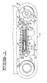
- a friction drive track belt mechanism 10 is suitably connected to a vehicle main frame partially, shown at 11 and includes an inextensible elastomeric endless track belt 12 entrained around a pair of axially space idler wheels 13 and a pair of drive wheels 14.
- the mechanism 10 includes variable leverage recoil mechanism 16 for resiliently resisting recoil movement of the idler wheels 13 toward the drive wheels 14.
- the recoil mechanism 16 in the embodiment illustrated, includes a roller frame 17, an elongate recoil spring mechanism 18, an idler wheel mounting bracket 19, and a pair of links 21 and 22.
- the roller frame 17 is suitably connected to the main frame 11 in the usual manner and includes an elongate lower beam 23 and an upper cylindrical portion 24.
- a plurality of rollers 26 are rotatably connected to a lower surface of the lower beam 23.
- a forward end portion 27 of the lower beam 23 extends forwardly between the pair of idler wheels 13.
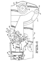
- the recoil spring mechanism 18 is contained within the cylindrical portion 24 of the roller frame 17 and has first and second end portions 28, 29 with the first end portion 28 being connected to the roller frame 17.
- the recoil spring mechanism 18 includes a recoil spring 31 and a spring support means 32 for supporting the recoil spring 31 and retaining the recoil spring in a pre-compressed condition.
- the spring support means 32 includes a tubular member 36 extending into one end of the recoil spring 31.
- the tubular member 36 has first and second bores 37, 38 therein with the first bore terminating at an annular shoulder 39.
- An annular flange 41 is integrally connected to an end of the tubular member 36.
- a mounting bracket 42 is secured to the flange 41 by a plurality of bolts 43 and is connected to the cylindrical portion 24 of the roller frame 17 with a pin 44.
- the support means also includes a rod 46 extending into the other end of the recoil spring and slidably extends through the second bore 38 of the tubular member 36.
- An annular flange 47 is integrally secured to the rod 36.
- a bifurcated bracket 48 extends from the flange 47 forwardly toward the idler wheels 13.
- a bolt 49 passes through a spacer 51 positioned for abutment with the shoulder 39 and threadably engages a threaded bore in the rod 46.
- An annular dust seal 52 is suitably connected to the annular flange 47 and sealingly contacts the inner surface of the cylindrical portion 24 of the roller frame 17.
- the mounting bracket 19 has first and second end portions 53, 54 and an intermediate portion 56 therebetween.
- the first end portion 53 is pivotally connected to the forward end portion 27 of the roller frame 17 by a pivot 57.
- a live shaft 58 extends through a bore 59 defined in the intermediate portion 56 of the mounting bracket 19 and is suitably journalled thereto by a bearing 60.
- the pair of idler wheels 13 are connected to the end portions of the shaft 58.
- the second end portion 54 of the mounting bracket 19 includes a pair of laterally spaced forwardly facing slots 61. The idler wheels 13 are thus swingably carried by the mounting bracket 19 so that they are movable toward and away from the drive wheels 14.
- this embodiment includes a pair of laterally spaced links 21 each of which can be selectively adjusted to change its effective length.
- Each of the links 21 is a multi-piece assembly including first and second members 62, 63 having overlapping portions releasably fastened together by a bolt 54.
- the first member 62 has an elongated slot 66 therein through which the bolt 54 extends.
- a pair of tapered surfaces 67 are formed on the first member 62.
- a pair of oppositely directed tapered surfaces 68 are similarly formed on the other member 63 in facing relationship to the tapered surfaces 67.
- a pair of wedges 69 are seated in the resulting "V" shaped slots formed by the tapered surfaces 67, 68.
- a threaded fastening means 70 is provided for controlling the relative positions of the wedges 69.
- the means 70 includes a bolt 71 and a nut 71a which retain the wedges in abutment with the tapered surfaces 67, 68.
- Both of the links 21 has first and second end portions 72, 73.
- the first end portions 72 of the pair of links 21 extends into the slots 61 of the mounting bracket 19 and are pivotally connected thereto by a pair of pivots 74.
- the second end portions 73 of the links 21 straddle the bifurcated bracket 48 and are pivotally connected thereto by a pivot 76.
- the link 22 has first and second end portions 77, 78 with the first end portion being pivotally connected to the roller frame 17 by a pivot 79.
- the second end portion 78 extends between the spaced apart elements of the bifurcated bracket 48 and is pivotally connected to both the bracket and the second end portion 73 of the links 21 by the common pivot 74.
- the link 22 extends through an elongated slot 81 in the roller frame 17 and includes a pair of arcuate surfaces 82, 83 having a center point coinciding with the axis of the pivot pin 76.
- the arcuate surface 82 is in close proximity to one end of the slot 81 and cooperates therewith to minimize the passage of foreign material through the slot 81.
- a scraper 84 is secured to the frame 17 at the other end of the elongate slot 81 by a bolt 86 in close proximity to the arcuate surface 83.
- the link 22 serves as a means 87 for guiding the pivot 74 between the link 21 and the recoil spring mechanism 18 in a preselected path.
- the tapered surfaces 67 and 68 of the first and second members 62, 63, the wedges 69 and the threaded fastening means 70 provide a means 88 for changing the effective length of the link 21.
- Figs. 1 and 2 show the idler wheels 13 and the variable leverage recoil mechanism 16 in their normal operating position.
- the upper run of the track belt 12 moves from left to right in the direction of the arrow.
- the upper run of the track belt moves from right to left when the vehicle is driven in reverse.
- the recoil spring 31 is retained in a pre-compressed condition between the flanges 41, 47 of the spring support means 32 and a preselected static tension is provided in the track belt 12.
- Static tension as hereinafter used is the tension in the track belt established by the relative position of the drive wheels 14 and idler wheels 13 when the vehicle is at rest.
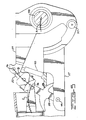
- the shaft 58 and the pivot 76 swing in an arcuate path represented by the arcs A & B respectively. Both the arcs are divided into spaces representing equal increments of idler wheel movement.
- An arc C represents the path of movement of the pivot 74. While the movement of the pivot 74 is basically rearwardly toward the drive wheels 14, the pivot 74 moves slightly upwardly away from the frame 17 during the initial portion of the arc. The arc C is divided to indicate corresponding increments of movement of the pivot 74 in relation to the equal increments of travel indicated on arcs A & B.
- the progressively shorter increments into which arc C is divided graphically illustrate that the pivot 74 moves progressively lesser distances for each fixed increment of idler wheel movement.
- Such lesser distances can be correlated to a progressive change in the effective movement arm whereby the variable leverage recoil mechanism 16 exhibits a progressively increasing mechanical advantage over the force of the recoil spring 31 during recoil movement of the idler wheels.
- the increase in the mechanical advantage over the recoil spring is sufficient to offset the increase in force required to compress the recoil spring 31 such that the tension in the track belt 12 remains substantially constant from the beginning of recoil to full recoil.
- the recoil spring 31 urges the bracket 48 forwardly causing the pin 74 to move forwardly in the arcuate path. This tends to move the links 21, 22 toward their former near straight line relationship thereby pivoting the mounting bracket 19 clockwise moving the idler wheels 13 toward their normal operating position.
- the recoil spring 31 is normally retained in a precompressed state.
- the amount of force exerted by the spring in the precompressed state in this embodiment is determined basically by two factors.
- the track drive in this embodiment is a friction drive arrangement wherein the power to the track belt 12 is provided by frictional contact between the track belt and the drive wheels 14.
- the position of the idler wheels 13 is adjusted in a manner hereinafter described to established a preselected static tension in the track belt.
- static tension applies a force to the idler wheels 13 urging the idler wheels rearwardly.
- such force is transmitted through the mounting bracket 19 and links 21, 22 so that the resultant force exerted against the recoil spring 31 is X units.
- the static tension in the track belt 12 is established by the length of the links 21.
- this is accomplished by positioning a hydraulic jack, schematically shown by broken lines at 90 on Fig. 5, of a preselected size at a preselected location between the second end portion 54 of the mounting bracket 19 and the roller frame 17.
- the bolts 64 holding the first and second members 62, 63 of the links 21 are loosened and the hydraulic jack pressurized to a preselected pressure to pivot the mounting bracket 19 clockwise about the pin 57.
- the nuts 71 on the bolt 70 are then tightened to force the wedges 69 into contact with the tapered surfaces 67, 68 and the bolts 64 retightened. It is assumed that the size of the hydraulic jack and the effective moment arm through which the force of the jack is applied to the mounting bracket 19 are known so that the preselected pressure needed to obtain the proper static tension is also known.
Landscapes
- Engineering & Computer Science (AREA)
- Chemical & Material Sciences (AREA)
- Combustion & Propulsion (AREA)
- Transportation (AREA)
- Mechanical Engineering (AREA)
- Devices For Conveying Motion By Means Of Endless Flexible Members (AREA)
- Liquid Crystal Substances (AREA)
- Pharmaceuticals Containing Other Organic And Inorganic Compounds (AREA)
- Organic Low-Molecular-Weight Compounds And Preparation Thereof (AREA)
Claims (9)
Applications Claiming Priority (2)
| Application Number | Priority Date | Filing Date | Title |
|---|---|---|---|
| US858789 | 1986-05-02 | ||
| US06/858,789 US4650260A (en) | 1986-05-02 | 1986-05-02 | Variable leverage recoil mechanism |
Publications (3)
| Publication Number | Publication Date |
|---|---|
| EP0265434A1 EP0265434A1 (de) | 1988-05-04 |
| EP0265434A4 EP0265434A4 (de) | 1988-05-31 |
| EP0265434B1 true EP0265434B1 (de) | 1990-12-05 |
Family
ID=25329190
Family Applications (1)
| Application Number | Title | Priority Date | Filing Date |
|---|---|---|---|
| EP86904654A Expired - Lifetime EP0265434B1 (de) | 1986-05-02 | 1986-07-14 | Kettenspann- und rückstossvorrichtung mit veränderlicher hebelkraft |
Country Status (7)
| Country | Link |
|---|---|
| US (1) | US4650260A (de) |
| EP (1) | EP0265434B1 (de) |
| JP (1) | JPS63503133A (de) |
| AU (1) | AU581775B2 (de) |
| DE (1) | DE3676094D1 (de) |
| WO (1) | WO1987006554A1 (de) |
| ZA (1) | ZA872831B (de) |
Families Citing this family (9)
| Publication number | Priority date | Publication date | Assignee | Title |
|---|---|---|---|---|
| US4836318A (en) * | 1987-08-28 | 1989-06-06 | Caterpillar Inc. | Track roller frame assembly |
| US4834478A (en) * | 1988-06-30 | 1989-05-30 | Caterpillar Inc. | Track roller frame assembly |
| US5368375A (en) * | 1993-08-24 | 1994-11-29 | Caterpillar Inc. | Belt tension indicating system |
| SE504474C2 (sv) * | 1995-06-16 | 1997-02-17 | Haegglunds Vehicle Ab | Fjädrande bandspänningsanordning för banddrivna fordon samt bandställsenhet innefattande sådan bandspänningsanordning |
| US6662421B1 (en) | 2001-06-25 | 2003-12-16 | Joe Krippelz, Sr. | Method and apparatus for installation of rubber tracks on vehicles |
| US7520575B2 (en) * | 2007-06-29 | 2009-04-21 | Agco Corporation | Tension management system for an endless track of a work machine |
| EP2050664B1 (de) * | 2007-10-18 | 2010-04-14 | Joseph Voegele AG | Raupenfahrwerk |
| US9988111B2 (en) * | 2016-08-04 | 2018-06-05 | Caterpillar Inc. | Swing arm idler rise height adjustment |
| US12030568B2 (en) * | 2020-01-17 | 2024-07-09 | Barreto Manufacturing, Inc. | Hydraulic tensioning system for track drive vehicle |
Family Cites Families (9)
| Publication number | Priority date | Publication date | Assignee | Title |
|---|---|---|---|---|
| US2017729A (en) * | 1934-03-30 | 1935-10-15 | Int Harvester Co | Track adjustment for track type tractors |
| US2326486A (en) * | 1940-07-26 | 1943-08-10 | Allis Chalmers Mfg Co | Track release mechanism |
| US2719062A (en) * | 1953-04-15 | 1955-09-27 | Arps Corp | Detachable half track attachment |
| US2843431A (en) * | 1956-12-28 | 1958-07-15 | John M Beaufort | Hydraulic track tensioning device |
| DE1108575B (de) * | 1960-10-17 | 1961-06-08 | Hugo Cordes Dipl Ing | Leitrad- und Kettenschutz fuer Gleiskettenfahrzeuge |
| DE1158379B (de) * | 1961-01-05 | 1963-11-28 | Hugo Cordes Dipl Ing | Hydraulisch-pneumatische Kettenspanneinrichtung fuer Gleiskettenfahrzeuge |
| FR1401309A (fr) * | 1964-04-20 | 1965-06-04 | Creusot Forges Ateliers | Véhicule à chenilles à poulies de tension réglables longitudinalement et verticalement |
| US3343889A (en) * | 1964-08-04 | 1967-09-26 | Int Harvester Co | Crawler tractor suspension |
| US3899218A (en) * | 1973-12-26 | 1975-08-12 | Caterpillar Tractor Co | Combined integral component enclosure and track roller frame |
-
1986
- 1986-05-02 US US06/858,789 patent/US4650260A/en not_active Expired - Fee Related
- 1986-07-14 EP EP86904654A patent/EP0265434B1/de not_active Expired - Lifetime
- 1986-07-14 WO PCT/US1986/001451 patent/WO1987006554A1/en not_active Ceased
- 1986-07-14 DE DE8686904654T patent/DE3676094D1/de not_active Expired - Fee Related
- 1986-07-14 AU AU61435/86A patent/AU581775B2/en not_active Ceased
- 1986-07-14 JP JP61504118A patent/JPS63503133A/ja active Pending
-
1987
- 1987-04-22 ZA ZA872831A patent/ZA872831B/xx unknown
Also Published As
| Publication number | Publication date |
|---|---|
| AU581775B2 (en) | 1989-03-02 |
| EP0265434A1 (de) | 1988-05-04 |
| JPS63503133A (ja) | 1988-11-17 |
| ZA872831B (en) | 1987-12-30 |
| DE3676094D1 (de) | 1991-01-17 |
| AU6143586A (en) | 1987-11-24 |
| EP0265434A4 (de) | 1988-05-31 |
| US4650260A (en) | 1987-03-17 |
| WO1987006554A1 (en) | 1987-11-05 |
Similar Documents
| Publication | Publication Date | Title |
|---|---|---|
| US4953919A (en) | Track suspension system | |
| CA1267669A (en) | Method and apparatus for tensioning frictionally driven, ground engaging belts | |
| EP1523438B1 (de) | Spannvorrichtung für eine raupenkette | |
| EP0613434B1 (de) | Fahrgestell für ein fahrzeug | |
| US4406501A (en) | Recoil system with guided slide assembly for track-type vehicles | |
| US4923257A (en) | Belted vehicle suspension system | |
| EP0265434B1 (de) | Kettenspann- und rückstossvorrichtung mit veränderlicher hebelkraft | |
| KR960015712B1 (ko) | 후륜조타장치 | |
| JPS6132193B2 (de) | ||
| GB2393696A (en) | Tensioning system for a tracked vehicle | |
| EP0426673B1 (de) | Raupenspann- und rücklaufvorrichtung | |
| KR0127287B1 (ko) | 후륜조타장치 | |
| US4147375A (en) | Central articulation for a self-propelling, articulated vehicle | |
| EP0664754B1 (de) | Anzeigevorrichtung für gleiskettenspannung | |
| CA1273037A (en) | Variable leverage recoil mechanism | |
| US4369854A (en) | Parking devices for vehicles | |
| JPH09226642A (ja) | ベルト型又は履帯型機械の下部構造体 | |
| AU691594B2 (en) | Rail vehicle | |
| SU1221016A1 (ru) | Гусеничный движитель |
Legal Events
| Date | Code | Title | Description |
|---|---|---|---|
| PUAI | Public reference made under article 153(3) epc to a published international application that has entered the european phase |
Free format text: ORIGINAL CODE: 0009012 |
|
| 17P | Request for examination filed |
Effective date: 19880128 |
|
| AK | Designated contracting states |
Kind code of ref document: A1 Designated state(s): BE DE FR GB IT |
|
| A4 | Supplementary search report drawn up and despatched |
Effective date: 19880531 |
|
| 17Q | First examination report despatched |
Effective date: 19900118 |
|
| GRAA | (expected) grant |
Free format text: ORIGINAL CODE: 0009210 |
|
| AK | Designated contracting states |
Kind code of ref document: B1 Designated state(s): BE DE FR GB IT |
|
| ITF | It: translation for a ep patent filed | ||
| ET | Fr: translation filed | ||
| REF | Corresponds to: |
Ref document number: 3676094 Country of ref document: DE Date of ref document: 19910117 |
|
| PGFP | Annual fee paid to national office [announced via postgrant information from national office to epo] |
Ref country code: FR Payment date: 19910605 Year of fee payment: 6 |
|
| PGFP | Annual fee paid to national office [announced via postgrant information from national office to epo] |
Ref country code: GB Payment date: 19910610 Year of fee payment: 6 |
|
| PGFP | Annual fee paid to national office [announced via postgrant information from national office to epo] |
Ref country code: BE Payment date: 19910619 Year of fee payment: 6 |
|
| PGFP | Annual fee paid to national office [announced via postgrant information from national office to epo] |
Ref country code: DE Payment date: 19910704 Year of fee payment: 6 |
|
| ITTA | It: last paid annual fee | ||
| PLBE | No opposition filed within time limit |
Free format text: ORIGINAL CODE: 0009261 |
|
| STAA | Information on the status of an ep patent application or granted ep patent |
Free format text: STATUS: NO OPPOSITION FILED WITHIN TIME LIMIT |
|
| 26N | No opposition filed | ||
| PG25 | Lapsed in a contracting state [announced via postgrant information from national office to epo] |
Ref country code: GB Effective date: 19920714 |
|
| PG25 | Lapsed in a contracting state [announced via postgrant information from national office to epo] |
Ref country code: BE Effective date: 19920731 |
|
| BERE | Be: lapsed |
Owner name: CATERPILLAR INC. Effective date: 19920731 |
|
| GBPC | Gb: european patent ceased through non-payment of renewal fee |
Effective date: 19920714 |
|
| PG25 | Lapsed in a contracting state [announced via postgrant information from national office to epo] |
Ref country code: FR Effective date: 19930331 |
|
| PG25 | Lapsed in a contracting state [announced via postgrant information from national office to epo] |
Ref country code: DE Effective date: 19930401 |
|
| REG | Reference to a national code |
Ref country code: FR Ref legal event code: ST |
|
| PG25 | Lapsed in a contracting state [announced via postgrant information from national office to epo] |
Ref country code: IT Free format text: LAPSE BECAUSE OF NON-PAYMENT OF DUE FEES;WARNING: LAPSES OF ITALIAN PATENTS WITH EFFECTIVE DATE BEFORE 2007 MAY HAVE OCCURRED AT ANY TIME BEFORE 2007. THE CORRECT EFFECTIVE DATE MAY BE DIFFERENT FROM THE ONE RECORDED. Effective date: 20050714 |