EP0264943A2 - Improved powder feeder - Google Patents
Improved powder feeder Download PDFInfo
- Publication number
- EP0264943A2 EP0264943A2 EP87115504A EP87115504A EP0264943A2 EP 0264943 A2 EP0264943 A2 EP 0264943A2 EP 87115504 A EP87115504 A EP 87115504A EP 87115504 A EP87115504 A EP 87115504A EP 0264943 A2 EP0264943 A2 EP 0264943A2
- Authority
- EP
- European Patent Office
- Prior art keywords
- powder
- axis
- container
- injection nozzle
- feeder
- Prior art date
- Legal status (The legal status is an assumption and is not a legal conclusion. Google has not performed a legal analysis and makes no representation as to the accuracy of the status listed.)
- Granted
Links
- 239000000843 powder Substances 0.000 title claims abstract description 110
- 238000002347 injection Methods 0.000 claims abstract description 26
- 239000007924 injection Substances 0.000 claims abstract description 26
- 239000011295 pitch Substances 0.000 claims abstract description 14
- 238000000034 method Methods 0.000 abstract description 5
- 238000005453 pelletization Methods 0.000 abstract description 2
- 239000003814 drug Substances 0.000 description 3
- 229940079593 drug Drugs 0.000 description 3
- 230000000694 effects Effects 0.000 description 3
- 239000008188 pellet Substances 0.000 description 3
- 239000011324 bead Substances 0.000 description 2
- 230000015572 biosynthetic process Effects 0.000 description 2
- 230000005484 gravity Effects 0.000 description 2
- 238000012986 modification Methods 0.000 description 2
- 230000004048 modification Effects 0.000 description 2
- 229920005596 polymer binder Polymers 0.000 description 2
- 239000002491 polymer binding agent Substances 0.000 description 2
- CIVCELMLGDGMKZ-UHFFFAOYSA-N 2,4-dichloro-6-methylpyridine-3-carboxylic acid Chemical compound CC1=CC(Cl)=C(C(O)=O)C(Cl)=N1 CIVCELMLGDGMKZ-UHFFFAOYSA-N 0.000 description 1
- 239000011248 coating agent Substances 0.000 description 1
- 238000000576 coating method Methods 0.000 description 1
- KWGRBVOPPLSCSI-UHFFFAOYSA-N d-ephedrine Natural products CNC(C)C(O)C1=CC=CC=C1 KWGRBVOPPLSCSI-UHFFFAOYSA-N 0.000 description 1
- 229960000525 diphenhydramine hydrochloride Drugs 0.000 description 1
- 238000004519 manufacturing process Methods 0.000 description 1
- 229960003447 pseudoephedrine hydrochloride Drugs 0.000 description 1
- BALXUFOVQVENIU-KXNXZCPBSA-N pseudoephedrine hydrochloride Chemical compound [H+].[Cl-].CN[C@@H](C)[C@@H](O)C1=CC=CC=C1 BALXUFOVQVENIU-KXNXZCPBSA-N 0.000 description 1
Images


Classifications
-
- B—PERFORMING OPERATIONS; TRANSPORTING
- B65—CONVEYING; PACKING; STORING; HANDLING THIN OR FILAMENTARY MATERIAL
- B65G—TRANSPORT OR STORAGE DEVICES, e.g. CONVEYORS FOR LOADING OR TIPPING, SHOP CONVEYOR SYSTEMS OR PNEUMATIC TUBE CONVEYORS
- B65G53/00—Conveying materials in bulk through troughs, pipes or tubes by floating the materials or by flow of gas, liquid or foam
- B65G53/34—Details
- B65G53/40—Feeding or discharging devices
- B65G53/48—Screws or like rotary conveyors
Definitions
- the present invention is directed to an apparatus for feeding powder and particularly to such an apparatus which smoothly delivers powder in a pelletization process without interruption.
- a process is known whereby drugs in powder form are coated onto small pellets or beads such as sugar seeds with the help of a sticky polymer binder. In order to effect such process it is necessary to uniformly feed the drug in powder form to the product bowl where the coating operation is performed.
- an apparatus having a novel structure is provided, with the result that continuous delivery of powder is provided.
- the above objects are accomplished by providing modifications to an existing powder feeder.
- the conventional powder injection nozzle which is shaped so as to include an abrupt change of direction or discontinuity is replaced with a powder injection nozzle which tapers smoothly without any discontinuity.
- the axis of the powder injection nozzle is arranged to be at an obtuse angle to the axis of the powder container so that the powder flows downwardly from the container into the injection nozzle.
- the pitch and shaft diameter of screw feed means used to feed the powder in the axis direction of the powder container are arranged to provide better feed control, and interchangeable screw feeds of varying pitch are provided for different powders.
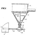
- a powder feeder in accordance with the prior art is depicted, and for example, this may correspond to the structure of the Glatt GPCG-5 Powder Coater Granulator with a rotor insert and equipped with the necessary accessories to manufacture pellets.
- powder is fed to powder container 2, and after being transported through the apparatus is fed continuously from blow-out jet 4 into product bowl 6.
- the powder may be coated onto small spherical beads or pellets, which for example may be sugar seeds which have been coated with a sticky polymer binder.
- the powder feeder after being fed to product container 2, the powder falls by gravity to portion 8 of the container, which is in the shape of a right circular cone. There, the powder is mixed by stripper 10, which is attached to shaft 12 for rotation.
- Feed screw 14 then moves the powder through relatively more narrow container portion 18, whereafter the powder is fed to powder injection nozzle 20.
- Compressed air entering through air hose 22 and nozzle orifice 24, factilitates feeding of the powder to and through injection nozzle 20.
- the powder is fed through connecting hose 26 and out of blow-out jet 4 into the product bowl 6.
- injection nozzle 20 is comprised of a conical mouth portion 30 which leads to and is terminated by a cylindrical portion 32 of relatively narrower diameter. At area 36, there is a change of direction and resultant discontinuity in the nozzle, and at this area there is a tendency for a powder plug to form. In addition to this, jet 4 is constricted at its end, and also may become backed up, especially if humidity conditions are not carefully controlled.
- powder injection nozzle 20 as shown in Figure 2 is replaced with powder injection nozzle 20 ⁇ .
- Nozzle 20 ⁇ is constructed so as to taper from a relatively wider mouth portion to a relatively narrower exit portion gradually, and without the presence of an abrupt change of direction or discontinuity such as is denoted by reference numeral 36 in Figure 2. This facilitates smooth flow of powder through nozzle 20 ⁇ without the occurrence of a plug or blockage.
- housing 25 of Figure 2 in which the powder injection nozzle and air jet are located is replaced by housing 25′ shown in Figure 3, which is located at an obtuse angle (axis a/axis b) with respect to cylindrical container 18.
- housing 25′ shown in Figure 3
- axis a/axis b obtuse angle
- the side of element 25 ⁇ which houses the powder injection nozzle is at an angle of 105° to cylindrical element 18, and such an embodiment is illustrated in Figure 4.
- blow out jet 4 has a constriction at its end, which as mentioned, tends to become blocked.
- blow out jet 4 is replaced with extension tube 38, which has an open end 40, which does not become blocked.
- a feed screw 14 is provided for moving the powder through cylindrical container 18.
- the original feed screw is cut off and replaced with feed screws which are customized to the particular powder being worked with. This provides better control over the powder being fed, and minimizes the effects of air from jet 24 which may circulate in container 18 and can interfere with the desired powder feed path. Since the powder feed can be influenced by the screw pitches, changes in pitch provides in addition to the helical screw speed and the compressed air pressure, a third dimension to controlling the feed rate.
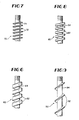
- Figure 6 shows a feed screw having two pitch per inch while Figure 7 shows a feed screw having four pitch per inch.
- Figure 8 shows a feed screw having three pitch per inch
- Figure 9 shows a feed screw having one pitch per inch.
- the thickness of the shaft e.g., identified by reference numeral 64 in Figure 6
- the modified feed screws are tapped into shaft 12, as at reference numeral 15.
- the apparatus of the invention may be used to feed many different powders.
- some drugs in powder form which may be pelletized by use of the powder feeder disclosed herein are pseudoephedrine hydrochloride and diphenhydramine hydrochloride, such as that capable of passing through a 60 mesh screen.
Landscapes
- Engineering & Computer Science (AREA)
- Mechanical Engineering (AREA)
- Disintegrating Or Milling (AREA)
- Screw Conveyors (AREA)
- Filling Or Emptying Of Bunkers, Hoppers, And Tanks (AREA)
- Nonmetallic Welding Materials (AREA)
- Formation And Processing Of Food Products (AREA)
- Detergent Compositions (AREA)
Abstract
Description
- The present invention is directed to an apparatus for feeding powder and particularly to such an apparatus which smoothly delivers powder in a pelletization process without interruption.
- A process is known whereby drugs in powder form are coated onto small pellets or beads such as sugar seeds with the help of a sticky polymer binder. In order to effect such process it is necessary to uniformly feed the drug in powder form to the product bowl where the coating operation is performed.
- There is known apparatus for feeding powder for the above-described purpose. However, it has been found that the prior art apparatus becomes backed up or clogged with the powder during operation, thereby resulting in interruption of the process line.
- In accordance with the present invention, an apparatus having a novel structure is provided, with the result that continuous delivery of powder is provided.
- It is therefore an object of the invention to provide a powder feeder which delivers powder smoothly and does not become clogged.
- It is a further object of the invention to modify an existing powder feeder so that delivery of powder is not interrupted by the formation of a powder plug.
- It is still a further object of the invention to effect modifications to an existing powder feeder which are relatively simple and inexpensive.
- In accordance with the invention, the above objects are accomplished by providing modifications to an existing powder feeder. In a first aspect of the invention, the conventional powder injection nozzle, which is shaped so as to include an abrupt change of direction or discontinuity is replaced with a powder injection nozzle which tapers smoothly without any discontinuity.
- In accordance with a further aspect of the invention, the axis of the powder injection nozzle is arranged to be at an obtuse angle to the axis of the powder container so that the powder flows downwardly from the container into the injection nozzle.
- In accordance with still further features of the present invention, the pitch and shaft diameter of screw feed means used to feed the powder in the axis direction of the powder container are arranged to provide better feed control, and interchangeable screw feeds of varying pitch are provided for different powders.
- The invention will be better understood by referring to the accompanying drawings, in which:
- Figure 1 is a schematic representation of a known powder feeder in accordance with the prior art.
- Figure 2 is a detailed schematic representation of a portion of the prior art powder feeder.
- Figure 3 is a schematic representation of improvements in accordance with the present invention.
- Figure 4 is a further schematic representation of improvements in accordance with the present invention.
- Figure 5 is a schematic representation of a powder feeder having the improved feed screw and means provided by the invention.
- Figures 6 to 9 are exemplary feed screws which are provided by the invention.
- Referring to Figure 1, a powder feeder in accordance with the prior art is depicted, and for example, this may correspond to the structure of the Glatt GPCG-5 Powder Coater Granulator with a rotor insert and equipped with the necessary accessories to manufacture pellets.
- In the operation of the apparatus shown in Figure 1, powder is fed to
powder container 2, and after being transported through the apparatus is fed continuously from blow-outjet 4 intoproduct bowl 6. - In the product bowl, the powder may be coated onto small spherical beads or pellets, which for example may be sugar seeds which have been coated with a sticky polymer binder.
- Referring more specifically to the operation of the powder feeder, after being fed to
product container 2, the powder falls by gravity toportion 8 of the container, which is in the shape of a right circular cone. There, the powder is mixed by stripper 10, which is attached toshaft 12 for rotation. - Feed
screw 14 then moves the powder through relatively morenarrow container portion 18, whereafter the powder is fed topowder injection nozzle 20. Compressed air, entering throughair hose 22 andnozzle orifice 24, factilitates feeding of the powder to and throughinjection nozzle 20. After the injection nozzle, the powder is fed through connectinghose 26 and out of blow-outjet 4 into theproduct bowl 6. - As mentioned above, a problem which has been encountered with the use of the prior art powder feeder is that it becomes backed up with powder, with the result that operation is interrupted.
- Referring to Figure 2, it is noted that
injection nozzle 20 is comprised of aconical mouth portion 30 which leads to and is terminated by acylindrical portion 32 of relatively narrower diameter. Atarea 36, there is a change of direction and resultant discontinuity in the nozzle, and at this area there is a tendency for a powder plug to form. In addition to this,jet 4 is constricted at its end, and also may become backed up, especially if humidity conditions are not carefully controlled. - Referring to Figure 3, expedients in accordance with the present invention for solving the above-described problems are depicted.
- In the arrangement of Figure 3,
powder injection nozzle 20 as shown in Figure 2, is replaced with powder injection nozzle 20ʹ. Nozzle 20ʹ is constructed so as to taper from a relatively wider mouth portion to a relatively narrower exit portion gradually, and without the presence of an abrupt change of direction or discontinuity such as is denoted byreference numeral 36 in Figure 2. This facilitates smooth flow of powder through nozzle 20ʹ without the occurrence of a plug or blockage. - Additionally,
housing 25 of Figure 2 in which the powder injection nozzle and air jet are located is replaced byhousing 25′ shown in Figure 3, which is located at an obtuse angle (axis a/axis b) with respect tocylindrical container 18. This disposes the entrance to nozzle 20ʹ in the path of powder flow, and since nozzle 20ʹ is directed downwardly, allows the force of gravity to augment the powder flow. In a preferred embodiment, the side of element 25ʹ which houses the powder injection nozzle is at an angle of 105° tocylindrical element 18, and such an embodiment is illustrated in Figure 4. - Referring again to the illustration of the prior art in Figure 2, it is noted that blow out
jet 4 has a constriction at its end, which as mentioned, tends to become blocked. - Referring to Figure 3, it is noted that blow out
jet 4 is replaced withextension tube 38, which has anopen end 40, which does not become blocked. - Thus, in accordance with the invention, as depicted in the embodiments of Figures 3 and 4, a structure is provided which eliminates the formation of a blockage at powder injection nozzle 20ʹ and thus provides for the uninterrupted flow of powder. Additionally, the problem wherein powder blockages formed at blow out
jet 4 has been obviated. - Further improvements which are provided by the present invention are illustrated in Figures 5 to 9.
- Referring to Figure 1, it is noted that in the prior art apparatus a
feed screw 14 is provided for moving the powder throughcylindrical container 18. In accordance with the invention, the original feed screw is cut off and replaced with feed screws which are customized to the particular powder being worked with. This provides better control over the powder being fed, and minimizes the effects of air fromjet 24 which may circulate incontainer 18 and can interfere with the desired powder feed path. Since the powder feed can be influenced by the screw pitches, changes in pitch provides in addition to the helical screw speed and the compressed air pressure, a third dimension to controlling the feed rate. - Typical feed screws which may be employed are illustrated in Figures 6 to 9.
- Thus, Figure 6 shows a feed screw having two pitch per inch while Figure 7 shows a feed screw having four pitch per inch. Similarly, Figure 8 shows a feed screw having three pitch per inch, while Figure 9 shows a feed screw having one pitch per inch. Additionally, the thickness of the shaft (e.g., identified by
reference numeral 64 in Figure 6) may be varied to further control powder feed. - As shown in Figure 5, the modified feed screws are tapped into
shaft 12, as atreference numeral 15. - It is to be understood that the apparatus of the invention may be used to feed many different powders. By way of non-limiting example, some drugs in powder form which may be pelletized by use of the powder feeder disclosed herein are pseudoephedrine hydrochloride and diphenhydramine hydrochloride, such as that capable of passing through a 60 mesh screen.
- While the invention has been described in accordance with illustrative embodiments, it should be understood that variations will occur to those skilled in the art, and the scope of the invention is to be limited only by the claims appended hereto and equivalents.
Claims (10)
a powder container (2) for receiving powder to be fed, said powder container (2) having an axis which lies in the direction of powder feed,
powder injection nozzle means (20) having an axis which is not co-linear with said container axis,
an orifice (24) for supplying gas under pressure having an axis which is co-linear with said powder injection nozzle means (20) axis, said gas under pressure being operational to feed said powder through said injection nozzle means (20), and
said powder injection nozzle means (20) having a wider diameter at its powder receiving end (30) and a narrower diameter at the powder exit end (32) and tapering from said wider to said narrower diameter gradually and without the presence of a discontinuity, wherein said powder is fed uninterruptedly through said powder injection nozzle means (20).
a powder container (2) for receiving powder to be fed, said container having an axis (a) which lies in the direction of powder feed,
powder injection nozzle means (20) having an axis (b),
an orifice (24) for supplying gas under pressure having an axis which is co-linear with said powder injection nozzle means (20) axis (b),
said gas under pressure being operative to feed said powder through said nozzle injection means (20), and said nozzle means (20) and orifice axes (axis b) being disposed at an obtuse angle with respect to said container axis (a), whereby said powder flows downwardly into said injection nozzle means. (20).
Priority Applications (1)
| Application Number | Priority Date | Filing Date | Title |
|---|---|---|---|
| AT87115504T ATE59364T1 (en) | 1986-10-23 | 1987-10-22 | FEED POWDER MATERIAL. |
Applications Claiming Priority (2)
| Application Number | Priority Date | Filing Date | Title |
|---|---|---|---|
| US92257886A | 1986-10-23 | 1986-10-23 | |
| US922578 | 1986-10-23 |
Publications (3)
| Publication Number | Publication Date |
|---|---|
| EP0264943A2 true EP0264943A2 (en) | 1988-04-27 |
| EP0264943A3 EP0264943A3 (en) | 1988-08-10 |
| EP0264943B1 EP0264943B1 (en) | 1990-12-27 |
Family
ID=25447249
Family Applications (1)
| Application Number | Title | Priority Date | Filing Date |
|---|---|---|---|
| EP87115504A Expired EP0264943B1 (en) | 1986-10-23 | 1987-10-22 | Improved powder feeder |
Country Status (5)
| Country | Link |
|---|---|
| EP (1) | EP0264943B1 (en) |
| AT (1) | ATE59364T1 (en) |
| DE (1) | DE3767121D1 (en) |
| ES (1) | ES2019358B3 (en) |
| GR (1) | GR3001249T3 (en) |
Cited By (5)
| Publication number | Priority date | Publication date | Assignee | Title |
|---|---|---|---|---|
| DE4306983A1 (en) * | 1993-03-05 | 1993-08-26 | Richard Lorke | Extruder for forming decorative work in cement mortar - has tapered conveyor base attached to conveyor housing with nozzle, conveyor screw connected to smaller screw in nozzle |
| DE19933707A1 (en) * | 1999-07-19 | 2001-01-25 | Johannes Moeller Hamburg Engin | Feeder for finely divided or powdery material |
| EP1426684A2 (en) * | 2002-03-06 | 2004-06-09 | GEOPLAST Kunststofftechnik Ges.m.b.H. | Device for receiving resp. storing and picking a solid or pourable fuel |
| CN115744310A (en) * | 2022-11-21 | 2023-03-07 | 西安西热锅炉环保工程有限公司 | Reducing self-suction paper basin vibration type multi-material synchronous mixing and continuous powder feeding device |
| CN116492549A (en) * | 2023-05-24 | 2023-07-28 | 重庆联佰博超医疗器械有限公司 | Fine powder spraying device |
Families Citing this family (1)
| Publication number | Priority date | Publication date | Assignee | Title |
|---|---|---|---|---|
| RU2514005C2 (en) * | 2012-05-10 | 2014-04-27 | Федеральное государственное бюджетное образовательное учреждение высшего профессионального образования "Национальный минерально-сырьевой университет "Горный" | Hydraulic conveyor |
Citations (2)
| Publication number | Priority date | Publication date | Assignee | Title |
|---|---|---|---|---|
| DE2923717A1 (en) * | 1979-06-12 | 1981-01-08 | Metallgesellschaft Ag | Measuring installation for fine pourable materials - includes storage container, conveyor system and regulating device with last two driven by common shaft |
| DE2930236A1 (en) * | 1979-07-26 | 1981-02-12 | Wyhlen Ag Eisenbau | Solid particle delivery equipment from vessel - has bucket wheel sluice valve discharging to transporting gas |
-
1987
- 1987-10-22 DE DE8787115504T patent/DE3767121D1/en not_active Expired - Fee Related
- 1987-10-22 EP EP87115504A patent/EP0264943B1/en not_active Expired
- 1987-10-22 ES ES87115504T patent/ES2019358B3/en not_active Expired - Lifetime
- 1987-10-22 AT AT87115504T patent/ATE59364T1/en not_active IP Right Cessation
-
1990
- 1990-12-28 GR GR90401030T patent/GR3001249T3/en unknown
Patent Citations (2)
| Publication number | Priority date | Publication date | Assignee | Title |
|---|---|---|---|---|
| DE2923717A1 (en) * | 1979-06-12 | 1981-01-08 | Metallgesellschaft Ag | Measuring installation for fine pourable materials - includes storage container, conveyor system and regulating device with last two driven by common shaft |
| DE2930236A1 (en) * | 1979-07-26 | 1981-02-12 | Wyhlen Ag Eisenbau | Solid particle delivery equipment from vessel - has bucket wheel sluice valve discharging to transporting gas |
Cited By (8)
| Publication number | Priority date | Publication date | Assignee | Title |
|---|---|---|---|---|
| DE4306983A1 (en) * | 1993-03-05 | 1993-08-26 | Richard Lorke | Extruder for forming decorative work in cement mortar - has tapered conveyor base attached to conveyor housing with nozzle, conveyor screw connected to smaller screw in nozzle |
| DE4306983C2 (en) * | 1993-03-05 | 1999-08-05 | Richard Lorke | Device with storage container and screw conveyor for dosing sieved cement mortar |
| DE19933707A1 (en) * | 1999-07-19 | 2001-01-25 | Johannes Moeller Hamburg Engin | Feeder for finely divided or powdery material |
| EP1426684A2 (en) * | 2002-03-06 | 2004-06-09 | GEOPLAST Kunststofftechnik Ges.m.b.H. | Device for receiving resp. storing and picking a solid or pourable fuel |
| EP1426684A3 (en) * | 2002-03-06 | 2005-02-02 | GEOPLAST Kunststofftechnik Ges.m.b.H. | Device for receiving resp. storing and picking a solid or pourable fuel |
| CN115744310A (en) * | 2022-11-21 | 2023-03-07 | 西安西热锅炉环保工程有限公司 | Reducing self-suction paper basin vibration type multi-material synchronous mixing and continuous powder feeding device |
| CN116492549A (en) * | 2023-05-24 | 2023-07-28 | 重庆联佰博超医疗器械有限公司 | Fine powder spraying device |
| CN116492549B (en) * | 2023-05-24 | 2023-11-21 | 重庆联佰博超医疗器械有限公司 | Fine powder spraying device |
Also Published As
| Publication number | Publication date |
|---|---|
| GR3001249T3 (en) | 1992-07-30 |
| EP0264943B1 (en) | 1990-12-27 |
| ES2019358B3 (en) | 1991-06-16 |
| DE3767121D1 (en) | 1991-02-07 |
| EP0264943A3 (en) | 1988-08-10 |
| ATE59364T1 (en) | 1991-01-15 |
Similar Documents
| Publication | Publication Date | Title |
|---|---|---|
| JPS62500377A (en) | screw powder feeder | |
| JPS6127294B2 (en) | ||
| US4044717A (en) | Apparatus for coating a surface with a pulverulent product | |
| US5660466A (en) | Apparatus and method for uniformly wetting hard-to-wet powders | |
| EP0695583A1 (en) | Powder paint supply device | |
| JP2014507965A (en) | Powder feeder | |
| JPH0745011B2 (en) | Method and apparatus for agglomerating and / or coating particles | |
| EP0264943A2 (en) | Improved powder feeder | |
| US2987221A (en) | Powder ejector assembly | |
| EP0850746A1 (en) | Discharge device for mixing and discharging solids of thermoplastic substance and fibers and plasticizing device having this device | |
| JPH0345151B2 (en) | ||
| US2604659A (en) | Feeding apparatus for plastic extruders | |
| CA2241229C (en) | Powder discharge apparatus and method for using the same | |
| US5498115A (en) | Distributor for particulate material | |
| EP0359113B1 (en) | Device for continuously delivering a powder in a gas stream | |
| EP0405969A1 (en) | Spray nozzle | |
| PT1771500E (en) | Method for mixing a plastic granulate with an additive and mixing device for carrying out said method and device provided with said mixing device | |
| DE2659058A1 (en) | Gas operated powder intake pipe - has concentric gas pipe producing conical current to loosen powder in vessel | |
| JP2006188302A (en) | Material supply device | |
| US3942721A (en) | Fluidized powder feed system for rotary distributor of electrostatic coating apparatus | |
| JP2518861Y2 (en) | Konjac molding equipment | |
| JPS582144B2 (en) | Continuous quantitative supply turntable feeder for powder and granular materials | |
| JPH0237782Y2 (en) | ||
| EP0205224A1 (en) | A pneumatic conveyor | |
| JPS6227234Y2 (en) |
Legal Events
| Date | Code | Title | Description |
|---|---|---|---|
| PUAI | Public reference made under article 153(3) epc to a published international application that has entered the european phase |
Free format text: ORIGINAL CODE: 0009012 |
|
| 17P | Request for examination filed |
Effective date: 19871022 |
|
| AK | Designated contracting states |
Kind code of ref document: A2 Designated state(s): AT BE CH DE ES FR GB GR IT LI LU NL SE |
|
| PUAL | Search report despatched |
Free format text: ORIGINAL CODE: 0009013 |
|
| AK | Designated contracting states |
Kind code of ref document: A3 Designated state(s): AT BE CH DE ES FR GB GR IT LI LU NL SE |
|
| 17Q | First examination report despatched |
Effective date: 19881216 |
|
| ITF | It: translation for a ep patent filed | ||
| GRAA | (expected) grant |
Free format text: ORIGINAL CODE: 0009210 |
|
| AK | Designated contracting states |
Kind code of ref document: B1 Designated state(s): AT BE CH DE ES FR GB GR IT LI LU NL SE |
|
| REF | Corresponds to: |
Ref document number: 59364 Country of ref document: AT Date of ref document: 19910115 Kind code of ref document: T |
|
| ET | Fr: translation filed | ||
| REF | Corresponds to: |
Ref document number: 3767121 Country of ref document: DE Date of ref document: 19910207 |
|
| PGFP | Annual fee paid to national office [announced via postgrant information from national office to epo] |
Ref country code: FR Payment date: 19910703 Year of fee payment: 5 |
|
| PGFP | Annual fee paid to national office [announced via postgrant information from national office to epo] |
Ref country code: SE Payment date: 19910712 Year of fee payment: 5 |
|
| PGFP | Annual fee paid to national office [announced via postgrant information from national office to epo] |
Ref country code: GB Payment date: 19910723 Year of fee payment: 5 |
|
| PGFP | Annual fee paid to national office [announced via postgrant information from national office to epo] |
Ref country code: LU Payment date: 19910724 Year of fee payment: 5 |
|
| PGFP | Annual fee paid to national office [announced via postgrant information from national office to epo] |
Ref country code: GR Payment date: 19910916 Year of fee payment: 5 |
|
| PGFP | Annual fee paid to national office [announced via postgrant information from national office to epo] |
Ref country code: BE Payment date: 19911024 Year of fee payment: 5 Ref country code: AT Payment date: 19911024 Year of fee payment: 5 |
|
| PGFP | Annual fee paid to national office [announced via postgrant information from national office to epo] |
Ref country code: CH Payment date: 19911025 Year of fee payment: 5 |
|
| PGFP | Annual fee paid to national office [announced via postgrant information from national office to epo] |
Ref country code: ES Payment date: 19911030 Year of fee payment: 5 |
|
| ITTA | It: last paid annual fee | ||
| PGFP | Annual fee paid to national office [announced via postgrant information from national office to epo] |
Ref country code: NL Payment date: 19911031 Year of fee payment: 5 |
|
| PLBE | No opposition filed within time limit |
Free format text: ORIGINAL CODE: 0009261 |
|
| STAA | Information on the status of an ep patent application or granted ep patent |
Free format text: STATUS: NO OPPOSITION FILED WITHIN TIME LIMIT |
|
| PGFP | Annual fee paid to national office [announced via postgrant information from national office to epo] |
Ref country code: DE Payment date: 19911126 Year of fee payment: 5 |
|
| 26N | No opposition filed | ||
| REG | Reference to a national code |
Ref country code: GR Ref legal event code: FG4A Free format text: 3001249 |
|
| EPTA | Lu: last paid annual fee | ||
| PG25 | Lapsed in a contracting state [announced via postgrant information from national office to epo] |
Ref country code: LU Free format text: LAPSE BECAUSE OF NON-PAYMENT OF DUE FEES Effective date: 19921022 Ref country code: GB Effective date: 19921022 Ref country code: AT Effective date: 19921022 |
|
| PG25 | Lapsed in a contracting state [announced via postgrant information from national office to epo] |
Ref country code: SE Effective date: 19921023 Ref country code: ES Free format text: LAPSE BECAUSE OF THE APPLICANT RENOUNCES Effective date: 19921023 |
|
| PG25 | Lapsed in a contracting state [announced via postgrant information from national office to epo] |
Ref country code: LI Effective date: 19921031 Ref country code: CH Effective date: 19921031 Ref country code: BE Effective date: 19921031 |
|
| BERE | Be: lapsed |
Owner name: WARNER-LAMBERT CY Effective date: 19921031 |
|
| PG25 | Lapsed in a contracting state [announced via postgrant information from national office to epo] |
Ref country code: GR Free format text: THE PATENT HAS BEEN ANNULLED BY A DECISION OF A NATIONAL AUTHORITY Effective date: 19930430 |
|
| PG25 | Lapsed in a contracting state [announced via postgrant information from national office to epo] |
Ref country code: NL Effective date: 19930501 |
|
| GBPC | Gb: european patent ceased through non-payment of renewal fee |
Effective date: 19921022 |
|
| NLV4 | Nl: lapsed or anulled due to non-payment of the annual fee | ||
| PG25 | Lapsed in a contracting state [announced via postgrant information from national office to epo] |
Ref country code: FR Effective date: 19930630 |
|
| REG | Reference to a national code |
Ref country code: CH Ref legal event code: PL |
|
| PG25 | Lapsed in a contracting state [announced via postgrant information from national office to epo] |
Ref country code: DE Effective date: 19930701 |
|
| REG | Reference to a national code |
Ref country code: FR Ref legal event code: ST |
|
| REG | Reference to a national code |
Ref country code: GR Ref legal event code: MM2A Free format text: 3001249 |
|
| EUG | Se: european patent has lapsed |
Ref document number: 87115504.0 Effective date: 19930510 |
|
| REG | Reference to a national code |
Ref country code: ES Ref legal event code: FD2A Effective date: 19991007 |
|
| PG25 | Lapsed in a contracting state [announced via postgrant information from national office to epo] |
Ref country code: IT Free format text: LAPSE BECAUSE OF NON-PAYMENT OF DUE FEES;WARNING: LAPSES OF ITALIAN PATENTS WITH EFFECTIVE DATE BEFORE 2007 MAY HAVE OCCURRED AT ANY TIME BEFORE 2007. THE CORRECT EFFECTIVE DATE MAY BE DIFFERENT FROM THE ONE RECORDED. Effective date: 20051022 |