EP0264451A1 - Installation a impulsions thermiques pour l'ebarbage - Google Patents
Installation a impulsions thermiques pour l'ebarbage Download PDFInfo
- Publication number
- EP0264451A1 EP0264451A1 EP86904468A EP86904468A EP0264451A1 EP 0264451 A1 EP0264451 A1 EP 0264451A1 EP 86904468 A EP86904468 A EP 86904468A EP 86904468 A EP86904468 A EP 86904468A EP 0264451 A1 EP0264451 A1 EP 0264451A1
- Authority
- EP
- European Patent Office
- Prior art keywords
- chamber
- space
- valve
- workpieces
- housing
- Prior art date
- Legal status (The legal status is an assumption and is not a legal conclusion. Google has not performed a legal analysis and makes no representation as to the accuracy of the status listed.)
- Granted
Links
Images

Classifications
-
- B—PERFORMING OPERATIONS; TRANSPORTING
- B23—MACHINE TOOLS; METAL-WORKING NOT OTHERWISE PROVIDED FOR
- B23D—PLANING; SLOTTING; SHEARING; BROACHING; SAWING; FILING; SCRAPING; LIKE OPERATIONS FOR WORKING METAL BY REMOVING MATERIAL, NOT OTHERWISE PROVIDED FOR
- B23D79/00—Methods, machines, or devices not covered elsewhere, for working metal by removal of material
- B23D79/005—Methods, machines, or devices not covered elsewhere, for working metal by removal of material for thermal deburring
Definitions
- the present invention relates to systems for deburring workpieces and relates to a thermal pulse system for deburring workpieces.
- a thermal pulse system for deburring workpieces which contains a C-shaped frame with a working chamber and a table with floors for receiving the workpieces, which is moved by means of a working cylinder (see, for example, US Pat. No. 3,666,252, class 266 / 2 R, announced on May 30, 1972).
- thermo-pulse system for deburring workpieces which contains a frame with a working chamber equipped with spark plugs, an inlet valve for filling the chamber with a fuel mixture, an outlet valve for the discharge of the combustion products from the chamber the chamber and a cover for receiving the workpieces to be treated, which can execute a reciprocating movement inside the chamber (see, for example, SU copyright certificate No. 988499, class B 23 K 28/00, B 23 K 7 / 06, announced on January 25, 1983).
- the outlet valve is located on the cover of the working chamber and is exposed to the direct effects of the hot combustion products generated when the fuel mixture is burned off.
- a gas flow acts on the exhaust valve, which contains particles of metal oxides and burned material of the ridges. Under these conditions, the valve is insufficiently resistant to the repetitive effects of the factors mentioned and must be replaced frequently.
- the present invention has for its object to scnaffen a thermal pulse system for deburring workpieces, in which the frame with the working chamber and the exhaust valve are designed so that the reliability and operational safety of the entire system and the life of the exhaust valve increases and significantly the noise level at Escape of the combustion products from the chamber is reduced while cleaning the combustion products from metal oxides and material particles of the removed ridges.
- a thermal pulse system for deburring workpieces which contains a frame with a working chamber with spark plugs, an inlet valve for filling the space of the chamber with a fuel mixture, an outlet valve for the discharge of the combustion products from the space of Chamber and a lid is provided for receiving the workpieces to be treated, which can perform a reciprocating movement inside the chamber
- the frame is in the form of a hollow housing
- the working chamber inside this housing with the formation of a space between the inner walls of the housing and the outer walls of the chamber for a liquid partially filling this space is housed
- the outlet valve is mounted in the lower part of the working chamber along its longitudinal axis along a liquid layer and openings are made in its side walls which provide the space for the liquid connect the space of the working chamber, and in the cover for receiving the workpieces to be treated on the side of the exhaust valve openings for the passage of the combustion products from the space of the working chamber through the inlet opening of the exhaust valve and its openings formed in the side walls into the
- Such a constructive design of the system according to the invention enables an increase in the reliability of the exhaust valve, a reduction in the noise generated when the combustion products emerge from the chamber of the working chamber after the treatment process and a cleaning of the combustion products mentioned from material particles contained in them and the burnt ridges and from metal oxides their passage through the liquid.
- the thermal pulse system according to the invention for deburring workpieces contains a frame.
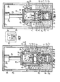
- the frame is in the form of a hollow housing 1 (Fig.1). Inside this housing 1 there is a chamber 2 which is fastened to the housing 1 with the aid of bolts 3. Between the inner walls 4 of the housing 1 and its bottom 5, the outer walls 6 of the chamber 2 and the bars 3 there is a space 7 for a liquid 8 which partially fills it.
- the housing and the chamber can have any shape suitable for the given purpose.
- the working chamber 2 has spark plugs 9, an inlet valve 10 for filling the space 11 of the chamber 2 with a fuel mixture (in the direction of arrow B), an outlet valve 12 for the exit of the combustion products from the space 11 of the chamber 2 (in the direction of arrow C , see FIG. 2) and a cover 13 (FIG. 1) for receiving the workpiece 14 to be treated, which has burrs 15 to be removed.
- spark plugs 9 and the valve 10 are installed in the chamber 2 on the part of the outer walls 6 above the bars 3.
- the outlet valve 12 is installed in the lower part of the working chamber 2 under a layer of the liquid 8 along the longitudinal axis 16 of the chamber 2.
- the outlet valve 12 contains a hollow housing 17, in which a slide 18 is accommodated with a sealing element 19, which goes into the inlet opening 20 of the valve 12, which is formed in one of the end faces 21 of the housing 17, and the bottom of the chamber 2 forms.
- the other end face 24 of the housing 17 has an opening 25.
- the end face 24 of the housing 17 is in the bottom 5 of the housing 1 installed.
- the lid 13 can perform a reciprocating movement inside the chamber 2 with the aid of a hydraulic cylinder 26.
- the hydraulic cylinder 26 is fastened in the upper part 27 of the housing 1.
- the cover 13 is designed in the form of a hollow housing 28.
- One end face 29 of the housing 28 is fastened to the piston rod 30 of the hydraulic cylinder 26, while the other end face 31 on the side of the exhaust valve 12 has openings 32 for the passage of the combustion products from the space 11 of the chamber 2 through the inlet opening 20 of the valve 12 , through a space 33 located above the slide 18 and through the openings 23 of the valve 12 into the liquid 8 and further into the space 7 and a tube 34 which is installed in one of the bolts 3 and out of the housing 1 through one of the windows 35 is led out, which are carried out in the side walls 36 of the housing 1 and are primarily intended for the placement of the workpieces 14 to be treated on the lid 13 and for the removal of the treated workpieces through windows 37 (FIG. 3) which are in the walls 38 of the housing 28 of the cover 13 are executed.
- the exhaust valve and the cover can have a b elie- bige, suitable for the given purpose form.
- the cover 13 In the starting position (FIG. 1), the cover 13 is in its upper end position. In this position, the workpiece 14 to be treated, which has burrs 15, is placed through the windows 35 and 37 on the end face 31 of the housing 28 of the cover 13.
- the slide 18 of the exhaust valve 13 is in its upper End position and closes the inlet opening 20 of the outlet valve 12 in that it rests with the sealing element 19 on the end wall 21 of the housing 17 of the valve 12.
- the hydraulic cylinder 26 sets the piston rod 30 in motion, and the cover 13 with the workpiece 14 to be treated on it assumes its lower end position .
- the end wall 31 of the housing 28 of the cover 13 comes to lie above the liquid 8.
- the inlet valve 10 in the direction of arrow B, the space 11 of the chamber 2 is filled with a fuel mixture. After the predetermined pressure has been reached in space 11, the fuel mixture is ignited with the aid of spark plug 9.
- the ridges 15 located on the workpiece 14 to be treated are burned and / or melted due to their developed surface and relatively small mass.
- the combustion products 40 displace the liquid 8 above the sealing element 19 through the opening 20 and the openings 23 and enter the space 7 through a layer of the liquid. They are cleaned of dust and small floating particles and give them their heat and energy from. Furthermore, they escape through the pipe 34 from the room 7 and from the system in the direction of arrow D.
- the openings 32 made in the end wall 31 of the housing 28 of the cover 13 serve for the passage of the combustion products 40 and for collecting larger particles of the burned ridges 15 and thus the protection of the sealing element 19 from damage.
- the system according to the invention enables an expansion of the nomenclature of the workpieces to be treated, since the excess heat of the scalding products is not transferred to the workpieces to be treated, but is removed from the working chamber through the outlet valve, which is particularly important for aluminum alloy workpieces and some others.
- the workpieces have a lower coating of metal oxides and particles of the burnt ridges after the treatment.
- the invention can be used in mechanical engineering companies for cleaning workpieces made of metal and plastic.
Landscapes
- Physics & Mathematics (AREA)
- Thermal Sciences (AREA)
- Optics & Photonics (AREA)
- Engineering & Computer Science (AREA)
- Mechanical Engineering (AREA)
- Crystals, And After-Treatments Of Crystals (AREA)
- Fuel-Injection Apparatus (AREA)
- Perforating, Stamping-Out Or Severing By Means Other Than Cutting (AREA)
- Cylinder Crankcases Of Internal Combustion Engines (AREA)
- Incineration Of Waste (AREA)
Abstract
Applications Claiming Priority (1)
| Application Number | Priority Date | Filing Date | Title |
|---|---|---|---|
| PCT/SU1986/000040 WO1987006513A1 (fr) | 1986-04-30 | 1986-04-30 | Installation a impulsions thermiques pour l'ebarbage |
Publications (3)
| Publication Number | Publication Date |
|---|---|
| EP0264451A1 true EP0264451A1 (fr) | 1988-04-27 |
| EP0264451A4 EP0264451A4 (fr) | 1989-04-05 |
| EP0264451B1 EP0264451B1 (fr) | 1991-08-28 |
Family
ID=21616992
Family Applications (1)
| Application Number | Title | Priority Date | Filing Date |
|---|---|---|---|
| EP86904468A Expired - Lifetime EP0264451B1 (fr) | 1986-04-30 | 1986-04-30 | Installation a impulsions thermiques pour l'ebarbage |
Country Status (5)
| Country | Link |
|---|---|
| US (1) | US4802654A (fr) |
| EP (1) | EP0264451B1 (fr) |
| JP (1) | JPS63503129A (fr) |
| DE (1) | DE3681172D1 (fr) |
| WO (1) | WO1987006513A1 (fr) |
Cited By (1)
| Publication number | Priority date | Publication date | Assignee | Title |
|---|---|---|---|---|
| DE4025566A1 (de) * | 1990-08-11 | 1992-02-13 | Audi Ag | Verfahren zum entgraten der kanten metallischer bauteile |
Families Citing this family (3)
| Publication number | Priority date | Publication date | Assignee | Title |
|---|---|---|---|---|
| US4993171B1 (en) * | 1989-11-22 | 1996-07-02 | Boc Group Inc | Covering for a hydraulic ram of a freeze dryer |
| SE465358B (sv) * | 1990-01-15 | 1991-09-02 | Asea Brown Boveri | Varmisostatisk hoegtryckspress anordnad foer snabbkylning av lastutrymmet |
| DE10116726A1 (de) * | 2001-04-04 | 2002-10-10 | Bosch Gmbh Robert | Anlage zur thermischen Behandlung von Werkstücken mit einem explosiven Gasgemisch, insbesondere thermische Entgratanlage |
Citations (3)
| Publication number | Priority date | Publication date | Assignee | Title |
|---|---|---|---|---|
| US1362535A (en) * | 1918-12-02 | 1920-12-14 | William M Hughes | Liquid-seal check-valve |
| SU795823A1 (ru) * | 1978-10-23 | 1981-01-15 | Харьковский Авиационный Институтим.H.E.Жуковского | Способ удалени заусенцев сиздЕлий |
| SU988499A1 (ru) * | 1981-04-03 | 1983-01-15 | Харьковский Ордена Ленина Авиационный Институт Им.Н.Е.Жуковского | Устройство дл термического удалени заусенцев с изделий |
Family Cites Families (5)
| Publication number | Priority date | Publication date | Assignee | Title |
|---|---|---|---|---|
| FR1568813A (fr) * | 1967-11-23 | 1969-05-30 | ||
| US3475229A (en) * | 1968-04-22 | 1969-10-28 | Chemotronics International Inc | Process for treating articles of manufacture to eliminate superfluous projections |
| US3666252A (en) * | 1970-05-25 | 1972-05-30 | Chemotronics International Inc | Apparatus for rapid high energy removal of superfluous projections |
| DE7927450U1 (de) * | 1979-09-27 | 1981-03-26 | Robert Bosch Gmbh, 70469 Stuttgart | Entgratkammer fuer thermisches entgraten |
| DE3204995A1 (de) * | 1982-02-12 | 1983-08-25 | Robert Bosch Gmbh, 7000 Stuttgart | Vorrichtung zur behandlung von werkstuecken in einer brennkammer |
-
1986
- 1986-04-30 DE DE8686904468T patent/DE3681172D1/de not_active Expired - Lifetime
- 1986-04-30 US US07/156,914 patent/US4802654A/en not_active Expired - Fee Related
- 1986-04-30 EP EP86904468A patent/EP0264451B1/fr not_active Expired - Lifetime
- 1986-04-30 JP JP61503682A patent/JPS63503129A/ja active Pending
- 1986-04-30 WO PCT/SU1986/000040 patent/WO1987006513A1/fr active IP Right Grant
Patent Citations (3)
| Publication number | Priority date | Publication date | Assignee | Title |
|---|---|---|---|---|
| US1362535A (en) * | 1918-12-02 | 1920-12-14 | William M Hughes | Liquid-seal check-valve |
| SU795823A1 (ru) * | 1978-10-23 | 1981-01-15 | Харьковский Авиационный Институтим.H.E.Жуковского | Способ удалени заусенцев сиздЕлий |
| SU988499A1 (ru) * | 1981-04-03 | 1983-01-15 | Харьковский Ордена Ленина Авиационный Институт Им.Н.Е.Жуковского | Устройство дл термического удалени заусенцев с изделий |
Non-Patent Citations (3)
| Title |
|---|
| See also references of WO8706513A1 * |
| SOVIET INVENTIONS ILLUSTRATED, Sektion M, Woche D40, 11. November 1981, Derwent Publications Ltd, GB; & SU-A-795 823 (KHARK AVIAT INST) 25-01-1981 * |
| SOVIET INVENTIONS ILLUSTRATED, Sektion M, Woche K45, 21. Dezember 1983, Derwent Publications Ltd, GB; & SU-A-988 499 (BOZHKO VP) 15-01-1983 * |
Cited By (1)
| Publication number | Priority date | Publication date | Assignee | Title |
|---|---|---|---|---|
| DE4025566A1 (de) * | 1990-08-11 | 1992-02-13 | Audi Ag | Verfahren zum entgraten der kanten metallischer bauteile |
Also Published As
| Publication number | Publication date |
|---|---|
| JPS63503129A (ja) | 1988-11-17 |
| EP0264451B1 (fr) | 1991-08-28 |
| WO1987006513A1 (fr) | 1987-11-05 |
| DE3681172D1 (de) | 1991-10-02 |
| EP0264451A4 (fr) | 1989-04-05 |
| US4802654A (en) | 1989-02-07 |
Similar Documents
| Publication | Publication Date | Title |
|---|---|---|
| DE3006332C2 (de) | Kolbenkompressor, insbesondere zum Verdichten von Sauerstoff | |
| DE3509439A1 (de) | Lueftungssystem fuer ein kurbelgehaeuse und verfahren zur entfernung von oelnebel von dem gas des systems | |
| DE2821164A1 (de) | Heissgasmotor | |
| DE2261621C3 (de) | Abgasreaktor für Brennkraftmaschinen | |
| EP0086264B1 (fr) | Dispositif de traitement de pièces dans une chambre de combustion | |
| DE69931802T2 (de) | Flammenrückschlagsicherung | |
| EP0264451B1 (fr) | Installation a impulsions thermiques pour l'ebarbage | |
| DE4130640C2 (de) | Vorrichtung und Verfahren zum Reinigen eines Filters | |
| DE4344700A1 (de) | Vorrichtung zum Reinigen schadstoffhaltiger Abluft aus Industrieanlagen durch regenerative Nachverbrennung | |
| EP0522245A1 (fr) | Filtre pour particules de suie | |
| DE3344704A1 (de) | Absperrarmatur fuer gasleitungen | |
| EP0281629A1 (fr) | Installation pour le sechage conductif de materiaux en vrac | |
| DE851863C (de) | Verbrennungskammer mit Zuendkerzenanordnung fuer Gasturbinen mit Gleichdruckverbrennung | |
| EP0370088A1 (fr) | Bruleur radiant pour combustible gazeux | |
| AT506459A2 (de) | Vorrichtung und verfahren zur reinigung von schadstoffhaltigem abgas | |
| DE4240202A1 (fr) | ||
| EP0139653A1 (fr) | Installation pour le traitement de pieces a usiner dans une chambre de combustion. | |
| DE7927450U1 (de) | Entgratkammer fuer thermisches entgraten | |
| EP0272323B1 (fr) | Dispositif d'ebarbage thermique | |
| DE4420477A1 (de) | Industriebrenner mit regenerativer Luftvorwärmung | |
| EP0310665A1 (fr) | Dispositif pour l'ebarbage thermique | |
| EP0622104B1 (fr) | Dispositif de filtrage de gaz chargés de poussières | |
| DE2346515C2 (de) | Industrie-Rauchgaskamin mit einem in einem Außenmantelrohr aufgehängten Stahl-Rauchgasrohr | |
| WO1987002124A1 (fr) | Four de fusion et de maintien en temperature | |
| DE4025933C2 (fr) |
Legal Events
| Date | Code | Title | Description |
|---|---|---|---|
| PUAI | Public reference made under article 153(3) epc to a published international application that has entered the european phase |
Free format text: ORIGINAL CODE: 0009012 |
|
| 17P | Request for examination filed |
Effective date: 19871217 |
|
| AK | Designated contracting states |
Kind code of ref document: A1 Designated state(s): DE FR GB IT SE |
|
| A4 | Supplementary search report drawn up and despatched |
Effective date: 19890405 |
|
| 17Q | First examination report despatched |
Effective date: 19901023 |
|
| GRAA | (expected) grant |
Free format text: ORIGINAL CODE: 0009210 |
|
| AK | Designated contracting states |
Kind code of ref document: B1 Designated state(s): DE FR GB IT SE |
|
| PG25 | Lapsed in a contracting state [announced via postgrant information from national office to epo] |
Ref country code: IT Free format text: LAPSE BECAUSE OF FAILURE TO SUBMIT A TRANSLATION OF THE DESCRIPTION OR TO PAY THE FEE WITHIN THE PRE;WARNING: LAPSES OF ITALIAN PATENTS WITH EFFECTIVE DATE BEFORE 2007 MAY HAVE OCCURRED AT ANY TIME BEFORE 2007. THE CORRECT EFFECTIVE DATE MAY BE DIFFERENT FROM THE ONE RECORDED.SCRIBED TIME-LIMIT Effective date: 19910828 |
|
| REF | Corresponds to: |
Ref document number: 3681172 Country of ref document: DE Date of ref document: 19911002 |
|
| GBT | Gb: translation of ep patent filed (gb section 77(6)(a)/1977) | ||
| ET | Fr: translation filed | ||
| PG25 | Lapsed in a contracting state [announced via postgrant information from national office to epo] |
Ref country code: GB Effective date: 19920430 |
|
| PG25 | Lapsed in a contracting state [announced via postgrant information from national office to epo] |
Ref country code: SE Effective date: 19920501 |
|
| PLBE | No opposition filed within time limit |
Free format text: ORIGINAL CODE: 0009261 |
|
| STAA | Information on the status of an ep patent application or granted ep patent |
Free format text: STATUS: NO OPPOSITION FILED WITHIN TIME LIMIT |
|
| 26N | No opposition filed | ||
| PG25 | Lapsed in a contracting state [announced via postgrant information from national office to epo] |
Ref country code: FR Effective date: 19921230 |
|
| PG25 | Lapsed in a contracting state [announced via postgrant information from national office to epo] |
Ref country code: DE Effective date: 19930101 |
|
| GBPC | Gb: european patent ceased through non-payment of renewal fee |
Effective date: 19920430 |
|
| REG | Reference to a national code |
Ref country code: FR Ref legal event code: ST |
|
| EUG | Se: european patent has lapsed |
Ref document number: 86904468.5 Effective date: 19921204 |