EP0263243B1 - Package assembly for an article - Google Patents
Package assembly for an article Download PDFInfo
- Publication number
- EP0263243B1 EP0263243B1 EP87109833A EP87109833A EP0263243B1 EP 0263243 B1 EP0263243 B1 EP 0263243B1 EP 87109833 A EP87109833 A EP 87109833A EP 87109833 A EP87109833 A EP 87109833A EP 0263243 B1 EP0263243 B1 EP 0263243B1
- Authority
- EP
- European Patent Office
- Prior art keywords
- flanges
- package assembly
- tube
- article
- housing portions
- Prior art date
- Legal status (The legal status is an assumption and is not a legal conclusion. Google has not performed a legal analysis and makes no representation as to the accuracy of the status listed.)
- Expired
Links
Images

Classifications
-
- B—PERFORMING OPERATIONS; TRANSPORTING
- B65—CONVEYING; PACKING; STORING; HANDLING THIN OR FILAMENTARY MATERIAL
- B65D—CONTAINERS FOR STORAGE OR TRANSPORT OF ARTICLES OR MATERIALS, e.g. BAGS, BARRELS, BOTTLES, BOXES, CANS, CARTONS, CRATES, DRUMS, JARS, TANKS, HOPPERS, FORWARDING CONTAINERS; ACCESSORIES, CLOSURES, OR FITTINGS THEREFOR; PACKAGING ELEMENTS; PACKAGES
- B65D45/00—Clamping or other pressure-applying devices for securing or retaining closure members
- B65D45/02—Clamping or other pressure-applying devices for securing or retaining closure members for applying axial pressure to engage closure with sealing surface
- B65D45/30—Annular members, e.g. with snap-over action or screw-threaded
Definitions
- the present invention relates to a packaged article, and more particularly, concerns a package assembly for an article which is sterilized after being packaged.
- US-A-2 681 142 describes a hard-shelled container for packaging easy damageable objects.
- the container comprises two housing portions each of which has a flange.
- Two diaphragms are positioned between the flanges of the container and between the diaphragms, the article is positioned in the interior of the container.
- the two flanges of the housing portions are secured to each other by a flexible partial ring grooved in its inner circumference.
- This partial ring which is of U-shaped cross-section may be formed of metal or plastic. It effects a tight juncture of the two housing portions.
- the ring member is not secured against unintended removal from the housing portions. Further, the ring member has, due to its U-shape, only a very limited resiliency.
- the first factor relates to convenience for the user.
- the package, while sealed to maintain sterility should be simple, straightforward and easy to open, while not disturbing the sterilized article contained inside the package.
- the second factor relates to manufacturing operations and cost.
- inexpensive materials, as well as simple, direct techniques for sealing the article inside the package, while not compromising on the quality of the packaged article, are the goals of the manufacturers of these packaged articles.
- ETO ethylene oxide
- Blister package components may be sealed by a number of different techniques including radio frequency (RF) sealing, staking or the use of snaps.
- RF radio frequency
- these sealing techniques have been known to restrict the movement of the blister package components, and cause warpage of the blister trays during the ETO sterilization procedures.
- the package contents are frequently disrupted or displaced upon opening due to uneven seal strength of the blister package components. Snaps are difficult to form in a reliable fashion, and often per form in an in cons is tent manner.
- a catheter set sold as the MINI-BALLOONTM catheter system by Becton, Dickinson and Company, Franklin Lakes, New Jersey employs a polyethylene tube to hold the upper and lower packaging trays together.
- the package trays, together with polyethylene securing tube are then inserted in a large blister tub which is sealed with a peelable cover for sterilization purposes. It is appreciated that the multiple packaging components not only adds expense and considerable bulk to the packaged product, but requires additional time and manipulation for gaining access to the sterilized product.
- the package assembly of the present invention has the features of claim 1.
- a package assembly in which the package components are securely and positively closed.
- Base of manufacture is a key feature of the present invention, as well as ease and convenience in opening the package assembly for gaining access to the article for use.
- the number of package components is held to a minimum in order to take cost constraints into account.
- assembling the package in the manufacturing operation is a straightforward procedure which takes a minimal amount of time to complete.
- the package assembly of the present invention is amenable to sterilization techniques, including ETO sterilization, simply by inserting the assembly into a pouch or the like.
- the preferred securing tube for holding the blister trays together not only holds the components securely together, but also allows for expansion during sterilization.
- the preferred securing tube as part of the present invention is easily removed by hand by the attendant immediately prior to using the packaged article. Further, the packaged assembly of the present invention may be opened in such a convenient way that the contents of the package should not be spilled which could cause damage or contamination.
- the package described here allows for ETO gas to easily flow into and out of the package.
- assembly 10 is comprised of a first or upper housing portion 12 and a second or lower housing portion 14. These housing portions may be in the form of trays, receptacles or other containers.
- housing portions 12 and 14 are commonly known as a blister package in which the housing portion includes one or more blister-like sections into which the article or parts of the article may be positioned.
- the housing portions of the present package assembly may be in the form of a tray and a cover or lid therefor. Therefore, it is appreciated that housing portions 12 and 14, although preferably in the form of blister packages, may take on many shapes and configurations for holding an article.
- housing portions 12 and 14 are substantially circular in cross-section, as more clearly seen in Figs. 1 and 2.
- an edge 15 of the housing portions is relatively straight as opposed to the remaining arcuate shape of the housing portions.
- Straight edge 15 is a relatively small portion of the periphery of the housing portions and is included to facilitate the assembly and subsequent removal of the securing tube which holds the housing portions together.
- first housing portion 12 includes an outwardly extending flange 16 extending around substantially the entire periphery thereof.
- second housing portion 14 has an outwardly extending flange 18 extending around substantially the entire periphery of the second housing portion.
- Flanges 16 and 18 are substantially flat or planar and lie in a substantially flat plane around the respective peripheries of the housing portions. It is preferred that flanges 16 and 18 be integrally formed with the first and second housing portions, respectively, so that the flanges and the housing portions may be made from the same material is an economic manufacturing operation, such as thermoforming.
- flanges 16 and 18 be of the same general shape and width around the peripheries of the first and second housing portions so that, when the housing portions are placed together, as seen in the drawings, the flanges are in surface-to-surface juxtaposition with each other in coextensive fashion.
- housing portion 12 When housing portion 12 is positioned with respect to housing portion 14, wherein the respective flanges are in mating engagement with each other, an interior compartment 19 is formed.
- one or more articles 20 Prior to mating the first and second housing portions together, one or more articles 20 are positioned to be maintained within compartment 20 in the final package.
- the preferred package assembly of the present invention is desirably suited to permit and maintain sterilization of the articles within the package.
- article 20 is preferably a medical article, and may be in many different forms or shapes. Although article 20 as illustrated in Fig. 4 is shown in block-like configuration, such representation is merely for illustrative purposes only.
- one or more of the respective housing portions may include shaped contours for defining a compartment to hold one or more articles of selected shapes, thereby minimizing the total amount of space that the housing portions require.
- flange 16 has a plurality of spaced-apart retaining dimples 22 protruding from the surface of that flange.
- Dimples 22 are preferably in the form of outwardly protruding detents, and are spaced around the periphery of the flange.
- dimples 22 need not be individualized or separated as illustrated in the drawings, but may be in the form of a continuous bump or ridge slightly inwardly spaced from the outer most edge of flange 16. Other configurations, shapes or locations of the retaining dimples may also be employed.
- dimples 22 may be on the surface of flange 16 or on flange 18 around second housing portion 14. It is also within the purview of the present invention to include dimples or the like on both flanges, if desired.
- tube 24 In order to hold together the two separate housing portions, a securing tube 24 is provided. It is preferred that tube 24 be resilient and substantially cylindrically shaped, although other shapes may be employed. Tube 24 is preferably hollow with a lumen 25 extending completely therethrough and surrounded by a wall 26 defining the body of tube 24. In order to impart resiliency to tube 24, it is preferred that the material out of which the tube is made be a polymeric material such as polyethylene, polypropylene, polyvinyl chloride and the like. As seen more clearly in Fig. 3, tube 24 is preferably elongate in nature and, due to its resiliency and flexibility, is readily bent or curved around its longitudinal axis 28 running through the tube.
- Extending parallel to longitudinal axis 28 is a slot 30 through wall 26 of the tube, thereby providing a discontinuity in the circular cross-section of the tube. Due the formed nature of the tube, and particularly when the tube is formed of polymeric material such as polyethylene, a spring-like resiliency is imparted to the slotted wall of the tube. Thus, the walls on either side of the slot tend to close-in toward each other thereby closing up the slot due to the spring-like characteristics inherent in this construction.
- tube 24 has been positioned over flanges 16 and 18.
- Tube 24 has been arcuately bent to assume the contour of the periphery of the respective flanges.
- Flanges 16 and 18, as well as retaining dimples 22 extend through slot 30 of the tube.
- the spring-like resiliency of the slotted wall of the tube provides a biasing force, in compression, to cause positive engagement between flanges 16 and 18. Therefore, tube 24, when properly positioned over the flanges, maintains the housing portions together with article 20 inside compartment 19.
- tube 24 extend in continuous fashion around substantially the entire arcuate peripheries of the juxtaposed flanges.
- one or more separate tubes to be employed, if desired at spaced intervals around the periphery of the flanges in order to hold the two housing portion together.
- the tube extend around the curved periphery of the flanges, while not covering straight edge 15 of the flanges.
- Package assembly 10 such as the embodiment illustrated in Fig. 1, is readily suitable for sterilization procedures, such as ETO sterilization.
- the package assembly may be placed in a pouch or like container, preferably flexible, which is constructed of materials representing a barrier to entrance of bacteria or microorganisms.
- one or more of the pouch materials preferably has sufficient porosity to permit the sterilization materials to penetrate into the interior of the pouch.
- Package assembly 10, as illustrated is normally itself not a bacteria barrier so that its contents may be sterilized in accordance with conventional sterilization procedures.
- the outer packaging materials into which package assembly 10 may be placed for sterilization and subsequent shipment may be chosen so as to be inexpensive and to minimize size or bulk.
- the present invention provides a package assembly which includes an article which may be sterilized after being packaged.
- the package components including the securing tube, provide a straightforward and inexpensive package, which may be readily opened by the user by hand without disrupting the contents within the package.
Abstract
Description
- The present invention relates to a packaged article, and more particularly, concerns a package assembly for an article which is sterilized after being packaged.
- US-A-2 681 142 describes a hard-shelled container for packaging easy damageable objects. The container comprises two housing portions each of which has a flange. Two diaphragms are positioned between the flanges of the container and between the diaphragms, the article is positioned in the interior of the container. The two flanges of the housing portions are secured to each other by a flexible partial ring grooved in its inner circumference. This partial ring which is of U-shaped cross-section may be formed of metal or plastic. It effects a tight juncture of the two housing portions. However, the ring member is not secured against unintended removal from the housing portions. Further, the ring member has, due to its U-shape, only a very limited resiliency.
- It is common and acceptable practice to pre-package medical articles prior to sterilization. Many medical products such as needles, syringes, catheters, cannulae and other devices normally intended for use in or on the body, or for use in a sterile environment, are required to be sterilized. If any of the aforementioned devices or products are intended for multiple uses, sterilization is usually performed by autoclaving techniques. However, many of these products are intended for one-time use and are disposable thereafter. These disposable, sterile products are typically packaged by the manufacturer, and then the packaged article or products are then sterilized in bulk. The articles inside the packages are maintained in a sterile condition by virtue of the properties or arrangement of the packaging material. Thus, when the user, such as a nurse, physician, hospital attendant or the like, is ready to make use of the article, the package is normally opened immediately before use of the article contained within.
- Since many disposable, sterile articles are packaged individually, there are at least two major considerations, in addition to the ability to permit and maintain sterilization, which should be taken into account with respect to the design of the packaging. The first factor relates to convenience for the user. In this regard, the package, while sealed to maintain sterility, should be simple, straightforward and easy to open, while not disturbing the sterilized article contained inside the package. The second factor relates to manufacturing operations and cost. Clearly since disposable medical articles are frequently packaged individually, the cost of the materials and labor for the packaging could become quite significant. Therefore, inexpensive materials, as well as simple, direct techniques for sealing the article inside the package, while not compromising on the quality of the packaged article, are the goals of the manufacturers of these packaged articles.
- Sterile, disposable medical products are often-times included in a blister package, usually in the form of a rigid tray and removable cover or lid sealed over the tray. The disposable article itself, is usually pre-packaged in the tray, and after the lid is sealed onto the tray, the packaged assembly, along with similar packaged assemblies, are sterilized in bulk. The most common technique for sterilization of these disposable medical articles is by ethylene oxide (ETO). While blister packages are quite common, effective to use and open, and are manufactured with cost constraints in mind, some problems, nevertheless, exist. Due to ETO sterilization, the package must be "breathable," i.e., allow ETO gas into package without allowing microorganisms to enter. Also ETO gas should be vented out of the package to keep residuals at acceptable levels. Blister package components may be sealed by a number of different techniques including radio frequency (RF) sealing, staking or the use of snaps. However, these sealing techniques have been known to restrict the movement of the blister package components, and cause warpage of the blister trays during the ETO sterilization procedures. In addition, the package contents are frequently disrupted or displaced upon opening due to uneven seal strength of the blister package components. Snaps are difficult to form in a reliable fashion, and often per form in an in cons is tent manner.
- Other techniques are known for holding blister trays or components together. For example, a catheter set sold as the MINI-BALLOON™ catheter system by Becton, Dickinson and Company, Franklin Lakes, New Jersey employs a polyethylene tube to hold the upper and lower packaging trays together. However, the package trays, together with polyethylene securing tube, are then inserted in a large blister tub which is sealed with a peelable cover for sterilization purposes. It is appreciated that the multiple packaging components not only adds expense and considerable bulk to the packaged product, but requires additional time and manipulation for gaining access to the sterilized product.
- Accordingly, improvements are still being sought in packaged assemblies suitable for medical articles which are to be sterilized and maintained in a sterilized condition until use. The present invention is directed to such an improvement which takes into account the two major considerations or goals set forth above for such packaged articles.
- It is the object of the invention to provide a package assembly for an article which allows for a ready sterilization of the article, safely contents the article without the danger of unintended opening, and is easy to open if required.
- The package assembly of the present invention has the features of claim 1.
- In accordance with the principles of the present invention, a package assembly is provided in which the package components are securely and positively closed. Base of manufacture is a key feature of the present invention, as well as ease and convenience in opening the package assembly for gaining access to the article for use. The number of package components is held to a minimum in order to take cost constraints into account. Further, assembling the package in the manufacturing operation is a straightforward procedure which takes a minimal amount of time to complete. Further, the package assembly of the present invention is amenable to sterilization techniques, including ETO sterilization, simply by inserting the assembly into a pouch or the like. The preferred securing tube for holding the blister trays together not only holds the components securely together, but also allows for expansion during sterilization. The preferred securing tube as part of the present invention is easily removed by hand by the attendant immediately prior to using the packaged article. Further, the packaged assembly of the present invention may be opened in such a convenient way that the contents of the package should not be spilled which could cause damage or contamination. The package described here allows for ETO gas to easily flow into and out of the package. Other features and advantages of the present invention will become more apparent after reading the Detailed Description which follows below.
- Fig. 1 is a perspective view of an embodiment of a package assembly for a packaged article embodying the features of the present invention;
- Fig. 2 is a top plan view of the package assembly of Fig. 1 illustrated with the securing tube removed so that the upper housing portion may be seen in its entirety;
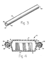
- Fig. 3 is a perspective view of the preferred embodiment of the securing tube as part of the package assembly of the present invention; and
- Fig. 4 is a cross-sectional view taken along line 4-4 of the embodiment of Fig. 1.
- While this invention is satisfied by embodiments in many different forms, there is shown in the drawings and will herein be described in detail a preferred embodiment of the invention, with the understanding that the present disclosure is to be considered as exemplary of the principles of the invention and is not intended to limit the invention to the embodiment illustrated. The scope of the invention will be measured by the appended claims and their equivalents.
- Adverting now to the drawings, there is illustrated a
package assembly 10 as it may appear in the form of one embodiment in accordance with the features of the instant invention. It can be seen thatassembly 10 is comprised of a first orupper housing portion 12 and a second orlower housing portion 14. These housing portions may be in the form of trays, receptacles or other containers. One preferred form forhousing portions housing portions - In the embodiment being described,
housing portions edge 15 of the housing portions is relatively straight as opposed to the remaining arcuate shape of the housing portions.Straight edge 15 is a relatively small portion of the periphery of the housing portions and is included to facilitate the assembly and subsequent removal of the securing tube which holds the housing portions together. - It can be seen in the drawings that
first housing portion 12 includes an outwardly extendingflange 16 extending around substantially the entire periphery thereof. In similar fashion,second housing portion 14 has an outwardly extendingflange 18 extending around substantially the entire periphery of the second housing portion.Flanges flanges flanges - When
housing portion 12 is positioned with respect tohousing portion 14, wherein the respective flanges are in mating engagement with each other, aninterior compartment 19 is formed. Prior to mating the first and second housing portions together, one ormore articles 20 are positioned to be maintained withincompartment 20 in the final package. The preferred package assembly of the present invention is desirably suited to permit and maintain sterilization of the articles within the package. To that end,article 20 is preferably a medical article, and may be in many different forms or shapes. Althougharticle 20 as illustrated in Fig. 4 is shown in block-like configuration, such representation is merely for illustrative purposes only. It is also preferred that one or more of the respective housing portions may include shaped contours for defining a compartment to hold one or more articles of selected shapes, thereby minimizing the total amount of space that the housing portions require. Oncearticle 20 is positioned withincompartment 19, and insofar as the article is suitable for sterilization techniques and subsequent storage and shipment, it is also a feature of the present invention to maintain the article within the compartment after assembly until the article is ready for use. - Along these lines, it can be seen in the drawings that flange 16 has a plurality of spaced-apart retaining
dimples 22 protruding from the surface of that flange.Dimples 22 are preferably in the form of outwardly protruding detents, and are spaced around the periphery of the flange. However, for purposes of the present invention, dimples 22 need not be individualized or separated as illustrated in the drawings, but may be in the form of a continuous bump or ridge slightly inwardly spaced from the outer most edge offlange 16. Other configurations, shapes or locations of the retaining dimples may also be employed. Further, it is understood thatdimples 22 may be on the surface offlange 16 or onflange 18 aroundsecond housing portion 14. It is also within the purview of the present invention to include dimples or the like on both flanges, if desired. - In order to hold together the two separate housing portions, a securing
tube 24 is provided. It is preferred thattube 24 be resilient and substantially cylindrically shaped, although other shapes may be employed.Tube 24 is preferably hollow with alumen 25 extending completely therethrough and surrounded by awall 26 defining the body oftube 24. In order to impart resiliency totube 24, it is preferred that the material out of which the tube is made be a polymeric material such as polyethylene, polypropylene, polyvinyl chloride and the like. As seen more clearly in Fig. 3,tube 24 is preferably elongate in nature and, due to its resiliency and flexibility, is readily bent or curved around itslongitudinal axis 28 running through the tube. Extending parallel tolongitudinal axis 28 is aslot 30 throughwall 26 of the tube, thereby providing a discontinuity in the circular cross-section of the tube. Due the formed nature of the tube, and particularly when the tube is formed of polymeric material such as polyethylene, a spring-like resiliency is imparted to the slotted wall of the tube. Thus, the walls on either side of the slot tend to close-in toward each other thereby closing up the slot due to the spring-like characteristics inherent in this construction. - As seen particularly in Figs. 1 and 4, taken in conjunction with Fig. 3,
tube 24 has been positioned overflanges Tube 24 has been arcuately bent to assume the contour of the periphery of the respective flanges.Flanges dimples 22 extend throughslot 30 of the tube. The spring-like resiliency of the slotted wall of the tube provides a biasing force, in compression, to cause positive engagement betweenflanges tube 24, when properly positioned over the flanges, maintains the housing portions together witharticle 20 insidecompartment 19. - It is preferred for purposes of the present invention that
tube 24 extend in continuous fashion around substantially the entire arcuate peripheries of the juxtaposed flanges. However, it is also within the purview of the present invention for one or more separate tubes to be employed, if desired at spaced intervals around the periphery of the flanges in order to hold the two housing portion together. For ease of assembly and subsequent removal oftube 24 from the flanges, it is desired that the tube extend around the curved periphery of the flanges, while not coveringstraight edge 15 of the flanges. - When it is time for
article 20 to be used, access tocompartment 19 is gained by removingtube 24 from the flanges. The resilient nature of the tube material allows manual manipulation of the tube so that it may be slid off the flanges. Further, while the dimples help retaintube 24 on the flanges prior to use, the retaining dimples are preferably shaped so that the wall of the tube may be slip or slide over the dimples for removal from the flanges. This arrangement as just described is readily amenable to manual manipulation without disrupting or disturbing the article or contents withincompartment 19 of the packaged assembly. -
Package assembly 10, such as the embodiment illustrated in Fig. 1, is readily suitable for sterilization procedures, such as ETO sterilization. The package assembly may be placed in a pouch or like container, preferably flexible, which is constructed of materials representing a barrier to entrance of bacteria or microorganisms. However, one or more of the pouch materials preferably has sufficient porosity to permit the sterilization materials to penetrate into the interior of the pouch.Package assembly 10, as illustrated, is normally itself not a bacteria barrier so that its contents may be sterilized in accordance with conventional sterilization procedures. However, due to the nature of securingtube 24 holding the housing portions together, the outer packaging materials into whichpackage assembly 10 may be placed for sterilization and subsequent shipment, may be chosen so as to be inexpensive and to minimize size or bulk. - Thus, the present invention provides a package assembly which includes an article which may be sterilized after being packaged. The package components, including the securing tube, provide a straightforward and inexpensive package, which may be readily opened by the user by hand without disrupting the contents within the package.
Claims (11)
a first housing portion (12) having an outwardly extending flange (16) around a periphery thereof;
a second housing portion (14) having an outwardly extending flange (18) around a periphery thereof;
said flanges being in surface-to-surface juxtaposition with each other and said housing portions defining an interior compartment (19) for accommodating an article (20);
a clamp having a slot (30) and being removably positioned over the juxtaposed flanges (16,18), said flanges (16,18) extending through said slot and said clamp causing positive engagement between the flanges to maintain the housing portions (12,14) together with the article (20) in said compartment (19),
characterized in that
said clamp is a resilient, substantially hollow cylindrical tube (24), said slot (30) extending through the wall (26) of the tube along the entire longitudinal axis thereof, and
at least one of said flanges (16,18) comprises a plurality of spaced-apart retaining dimples (22) embraced by the tube.
Priority Applications (1)
| Application Number | Priority Date | Filing Date | Title |
|---|---|---|---|
| AT87109833T ATE69425T1 (en) | 1986-10-06 | 1987-07-08 | PACKAGING DEVICE FOR AN OBJECT. |
Applications Claiming Priority (2)
| Application Number | Priority Date | Filing Date | Title |
|---|---|---|---|
| US915349 | 1986-10-06 | ||
| US06/915,349 US4699291A (en) | 1986-10-06 | 1986-10-06 | Package assembly for an article |
Publications (3)
| Publication Number | Publication Date |
|---|---|
| EP0263243A2 EP0263243A2 (en) | 1988-04-13 |
| EP0263243A3 EP0263243A3 (en) | 1989-04-26 |
| EP0263243B1 true EP0263243B1 (en) | 1991-11-13 |
Family
ID=25435606
Family Applications (1)
| Application Number | Title | Priority Date | Filing Date |
|---|---|---|---|
| EP87109833A Expired EP0263243B1 (en) | 1986-10-06 | 1987-07-08 | Package assembly for an article |
Country Status (6)
| Country | Link |
|---|---|
| US (1) | US4699291A (en) |
| EP (1) | EP0263243B1 (en) |
| AT (1) | ATE69425T1 (en) |
| DE (1) | DE3774524D1 (en) |
| ES (1) | ES2026488T3 (en) |
| GR (1) | GR3003117T3 (en) |
Families Citing this family (19)
| Publication number | Priority date | Publication date | Assignee | Title |
|---|---|---|---|---|
| DE4008265C2 (en) * | 1990-03-15 | 1993-11-25 | Reinhard Buchter | Reusable plastic packaging for ready meals |
| US4995523A (en) * | 1990-05-29 | 1991-02-26 | Sta-Rite Industries, Inc. | Tank clamping mechanism |
| US5421473A (en) * | 1991-07-23 | 1995-06-06 | Radley Valley Pty Ltd. | Heat resistant plastics container closure |
| US5301826A (en) * | 1992-08-06 | 1994-04-12 | Alternative Pioneering Systems, Inc. | Expansion ring and clip for use with an expandable oven |
| DE4325205A1 (en) * | 1993-07-27 | 1995-02-02 | Robert Pappler | Container for food, in particular for serving, storing and transporting, and the associated connecting body |
| US5392940A (en) * | 1993-08-23 | 1995-02-28 | Hueter Toledo, Inc. | Pet waste disposal system |
| DE4410943A1 (en) * | 1994-03-29 | 1995-10-05 | Robert Pappler | Food container for serving, storing and transporting food |
| DE4410945A1 (en) * | 1994-03-29 | 1995-10-05 | Robert Pappler | Container for serving, storing and transporting food |
| FR2766160B1 (en) * | 1997-07-18 | 1999-09-10 | Groupe Guillin Sa | PACKAGING BOX HAVING A CROWN |
| US6076676A (en) * | 1998-05-19 | 2000-06-20 | Cako Development Corporation | Method and Apparatus for packaging large cakes |
| US6170663B1 (en) | 1999-10-26 | 2001-01-09 | Sony Corporation | Clamshell package including three dimensional insert |
| US6227369B1 (en) * | 1999-10-29 | 2001-05-08 | Sony Corporation | Clamshell package including both permanent and resealable fastening structure |
| GB0512146D0 (en) * | 2005-06-15 | 2005-07-20 | Davidson Roderick I | Transport package |
| US8522674B2 (en) * | 2006-10-25 | 2013-09-03 | Tai Yu International Mey, Ltd. | Culinary steamer |
| NL2001876C2 (en) * | 2008-08-06 | 2010-02-09 | Allplast B V | Pressure resistant package for transporting for instance hazardous hazardous contents such as a diagnostic specimen and a kit or package parts for forming such a package. |
| US9694672B2 (en) * | 2010-06-14 | 2017-07-04 | Ford Global Technologies, Llc | Compliance structure for a distensible fuel tank |
| TWM440278U (en) * | 2012-06-22 | 2012-11-01 | Jia-Hao Lin | Packaging box structure of mobile phone set protective cover |
| US11136168B2 (en) * | 2014-08-14 | 2021-10-05 | Daniel Luch | Package with tamper evident security band |
| FR3047233A1 (en) * | 2016-02-02 | 2017-08-04 | Eric Enjolras | ON PACKAGING CARDBOARD FOR TRAFFIC TRAFFIC TYPE MULTIPACK |
Family Cites Families (9)
| Publication number | Priority date | Publication date | Assignee | Title |
|---|---|---|---|---|
| US239225A (en) * | 1881-03-22 | Christian claussen | ||
| US816338A (en) * | 1904-10-08 | 1906-03-27 | American Paper Bottle Co | Paper box or container. |
| US1921015A (en) * | 1927-11-30 | 1933-08-08 | American Can Co | Packaging of gas containing objects |
| US2681142A (en) * | 1950-11-08 | 1954-06-15 | Harold L Cohen | Sealed cushioning container |
| US2784675A (en) * | 1952-12-22 | 1957-03-12 | Borg Warner | Hydrodynamic coupling |
| US3217867A (en) * | 1963-10-21 | 1965-11-16 | Brite Mfg Co | Package for displaying elongated articles |
| IT959431B (en) * | 1972-05-04 | 1973-11-10 | Italvalmet Srl | SYSTEM FOR QUICK AND EASY ASSEMBLY AND DISASSEMBLY OF BALLS OR OTHER HOLLOW BODIES IN TWO CAPS OF VACUUM-MOLDED THERMOPLASTIC FOIL OR SIMILAR TO BUILD DECORATED ELEMENTS VI OR MORE |
| US3940008A (en) * | 1972-05-22 | 1976-02-24 | Flanders Robert D | Collapsible reusable barrel for fluids |
| US4033452A (en) * | 1973-08-30 | 1977-07-05 | Therrien Norman W | Display container |
-
1986
- 1986-10-06 US US06/915,349 patent/US4699291A/en not_active Expired - Fee Related
-
1987
- 1987-07-08 AT AT87109833T patent/ATE69425T1/en not_active IP Right Cessation
- 1987-07-08 EP EP87109833A patent/EP0263243B1/en not_active Expired
- 1987-07-08 DE DE8787109833T patent/DE3774524D1/en not_active Expired - Fee Related
- 1987-07-08 ES ES198787109833T patent/ES2026488T3/en not_active Expired - Lifetime
-
1991
- 1991-11-14 GR GR91401628T patent/GR3003117T3/en unknown
Also Published As
| Publication number | Publication date |
|---|---|
| US4699291A (en) | 1987-10-13 |
| ATE69425T1 (en) | 1991-11-15 |
| EP0263243A2 (en) | 1988-04-13 |
| ES2026488T3 (en) | 1992-05-01 |
| GR3003117T3 (en) | 1993-02-17 |
| EP0263243A3 (en) | 1989-04-26 |
| DE3774524D1 (en) | 1991-12-19 |
Similar Documents
| Publication | Publication Date | Title |
|---|---|---|
| EP0263243B1 (en) | Package assembly for an article | |
| US4798292A (en) | Sterilization, storage, and presentation container for surgical instruments | |
| EP3136941B1 (en) | Endoscope support tray and method for storing and transporting endoscopes | |
| US4226328A (en) | Catheterization package | |
| US5031768A (en) | Instrument tray and disposable receptacle having alternative locking means | |
| US5390792A (en) | Sterile packaging | |
| US4697703A (en) | Joint prosthesis package | |
| US5323902A (en) | Safety device for holding and retaining hyposyringes and the like | |
| US9265578B2 (en) | Multi-component packages for medical devices | |
| US5178282A (en) | Modular surgical packaging system | |
| US5127523A (en) | Container made of plastic for the disposal of disposable medical utensils and devices | |
| EP0544429A1 (en) | Disposable microwavable food container | |
| US20060151509A1 (en) | Sterile container and lid for a sterile container | |
| US10485627B2 (en) | Containment sleeves for packages containing medical devices | |
| JP2012505132A (en) | cover | |
| JPWO2018038078A1 (en) | Medical device package | |
| US6540078B1 (en) | Closable container comprising at least three trays | |
| WO2005122913A2 (en) | Container for packaging and deploying devices | |
| EP2155570B1 (en) | Dual pack container | |
| EP3752087A1 (en) | Protective container for sterilized medical implants | |
| EP3381486B1 (en) | Package for medical product | |
| JP2009502241A (en) | Waste containers for walls in hospitals and laboratories | |
| US3138253A (en) | Packaged medical trays | |
| US5392909A (en) | Releasable universal blister package for elongated surgical devices | |
| US6237770B1 (en) | Container with reinforced tab |
Legal Events
| Date | Code | Title | Description |
|---|---|---|---|
| PUAI | Public reference made under article 153(3) epc to a published international application that has entered the european phase |
Free format text: ORIGINAL CODE: 0009012 |
|
| AK | Designated contracting states |
Kind code of ref document: A2 Designated state(s): AT BE CH DE ES FR GB GR IT LI NL SE |
|
| PUAL | Search report despatched |
Free format text: ORIGINAL CODE: 0009013 |
|
| RHK1 | Main classification (correction) |
Ipc: B65D 45/30 |
|
| AK | Designated contracting states |
Kind code of ref document: A3 Designated state(s): AT BE CH DE ES FR GB GR IT LI NL SE |
|
| 17P | Request for examination filed |
Effective date: 19891007 |
|
| 17Q | First examination report despatched |
Effective date: 19900925 |
|
| GRAA | (expected) grant |
Free format text: ORIGINAL CODE: 0009210 |
|
| AK | Designated contracting states |
Kind code of ref document: B1 Designated state(s): AT BE CH DE ES FR GB GR IT LI NL SE |
|
| REF | Corresponds to: |
Ref document number: 69425 Country of ref document: AT Date of ref document: 19911115 Kind code of ref document: T |
|
| ITF | It: translation for a ep patent filed |
Owner name: ING. C. GREGORJ S.P.A. |
|
| REF | Corresponds to: |
Ref document number: 3774524 Country of ref document: DE Date of ref document: 19911219 |
|
| ET | Fr: translation filed | ||
| REG | Reference to a national code |
Ref country code: ES Ref legal event code: FG2A Ref document number: 2026488 Country of ref document: ES Kind code of ref document: T3 |
|
| PLBE | No opposition filed within time limit |
Free format text: ORIGINAL CODE: 0009261 |
|
| STAA | Information on the status of an ep patent application or granted ep patent |
Free format text: STATUS: NO OPPOSITION FILED WITHIN TIME LIMIT |
|
| REG | Reference to a national code |
Ref country code: GR Ref legal event code: FG4A Free format text: 3003117 |
|
| 26N | No opposition filed | ||
| EAL | Se: european patent in force in sweden |
Ref document number: 87109833.1 |
|
| PGFP | Annual fee paid to national office [announced via postgrant information from national office to epo] |
Ref country code: GB Payment date: 19950627 Year of fee payment: 9 |
|
| PGFP | Annual fee paid to national office [announced via postgrant information from national office to epo] |
Ref country code: DE Payment date: 19950710 Year of fee payment: 9 |
|
| PGFP | Annual fee paid to national office [announced via postgrant information from national office to epo] |
Ref country code: FR Payment date: 19950711 Year of fee payment: 9 |
|
| PGFP | Annual fee paid to national office [announced via postgrant information from national office to epo] |
Ref country code: CH Payment date: 19950713 Year of fee payment: 9 Ref country code: AT Payment date: 19950713 Year of fee payment: 9 |
|
| PGFP | Annual fee paid to national office [announced via postgrant information from national office to epo] |
Ref country code: SE Payment date: 19950717 Year of fee payment: 9 |
|
| PGFP | Annual fee paid to national office [announced via postgrant information from national office to epo] |
Ref country code: NL Payment date: 19950727 Year of fee payment: 9 Ref country code: ES Payment date: 19950727 Year of fee payment: 9 |
|
| PGFP | Annual fee paid to national office [announced via postgrant information from national office to epo] |
Ref country code: GR Payment date: 19950728 Year of fee payment: 9 |
|
| PGFP | Annual fee paid to national office [announced via postgrant information from national office to epo] |
Ref country code: BE Payment date: 19950911 Year of fee payment: 9 |
|
| PG25 | Lapsed in a contracting state [announced via postgrant information from national office to epo] |
Ref country code: GB Effective date: 19960708 Ref country code: AT Effective date: 19960708 |
|
| PG25 | Lapsed in a contracting state [announced via postgrant information from national office to epo] |
Ref country code: SE Effective date: 19960709 Ref country code: ES Free format text: LAPSE BECAUSE OF EXPIRATION OF PROTECTION Effective date: 19960709 |
|
| PG25 | Lapsed in a contracting state [announced via postgrant information from national office to epo] |
Ref country code: LI Effective date: 19960731 Ref country code: CH Effective date: 19960731 Ref country code: BE Effective date: 19960731 |
|
| BERE | Be: lapsed |
Owner name: BECTON DICKINSON & CY Effective date: 19960731 |
|
| PG25 | Lapsed in a contracting state [announced via postgrant information from national office to epo] |
Ref country code: GR Free format text: THE PATENT HAS BEEN ANNULLED BY A DECISION OF A NATIONAL AUTHORITY Effective date: 19970131 |
|
| PG25 | Lapsed in a contracting state [announced via postgrant information from national office to epo] |
Ref country code: NL Effective date: 19970201 |
|
| GBPC | Gb: european patent ceased through non-payment of renewal fee |
Effective date: 19960708 |
|
| REG | Reference to a national code |
Ref country code: GR Ref legal event code: MM2A Free format text: 3003117 |
|
| REG | Reference to a national code |
Ref country code: CH Ref legal event code: PL |
|
| PG25 | Lapsed in a contracting state [announced via postgrant information from national office to epo] |
Ref country code: FR Effective date: 19970328 |
|
| NLV4 | Nl: lapsed or anulled due to non-payment of the annual fee |
Effective date: 19970201 |
|
| PG25 | Lapsed in a contracting state [announced via postgrant information from national office to epo] |
Ref country code: DE Effective date: 19970402 |
|
| EUG | Se: european patent has lapsed |
Ref document number: 87109833.1 |
|
| REG | Reference to a national code |
Ref country code: FR Ref legal event code: ST |
|
| REG | Reference to a national code |
Ref country code: ES Ref legal event code: FD2A Effective date: 19990601 |
|
| PG25 | Lapsed in a contracting state [announced via postgrant information from national office to epo] |
Ref country code: IT Free format text: LAPSE BECAUSE OF NON-PAYMENT OF DUE FEES;WARNING: LAPSES OF ITALIAN PATENTS WITH EFFECTIVE DATE BEFORE 2007 MAY HAVE OCCURRED AT ANY TIME BEFORE 2007. THE CORRECT EFFECTIVE DATE MAY BE DIFFERENT FROM THE ONE RECORDED. Effective date: 20050708 |