EP0262851A2 - A coaxial cable connector - Google Patents
A coaxial cable connector Download PDFInfo
- Publication number
- EP0262851A2 EP0262851A2 EP87308366A EP87308366A EP0262851A2 EP 0262851 A2 EP0262851 A2 EP 0262851A2 EP 87308366 A EP87308366 A EP 87308366A EP 87308366 A EP87308366 A EP 87308366A EP 0262851 A2 EP0262851 A2 EP 0262851A2
- Authority
- EP
- European Patent Office
- Prior art keywords
- connector
- conductor
- coaxial cable
- cylinder
- central
- Prior art date
- Legal status (The legal status is an assumption and is not a legal conclusion. Google has not performed a legal analysis and makes no representation as to the accuracy of the status listed.)
- Granted
Links
Images
Classifications
-
- H—ELECTRICITY
- H01—ELECTRIC ELEMENTS
- H01R—ELECTRICALLY-CONDUCTIVE CONNECTIONS; STRUCTURAL ASSOCIATIONS OF A PLURALITY OF MUTUALLY-INSULATED ELECTRICAL CONNECTING ELEMENTS; COUPLING DEVICES; CURRENT COLLECTORS
- H01R24/00—Two-part coupling devices, or either of their cooperating parts, characterised by their overall structure
- H01R24/38—Two-part coupling devices, or either of their cooperating parts, characterised by their overall structure having concentrically or coaxially arranged contacts
- H01R24/40—Two-part coupling devices, or either of their cooperating parts, characterised by their overall structure having concentrically or coaxially arranged contacts specially adapted for high frequency
- H01R24/54—Intermediate parts, e.g. adapters, splitters or elbows
- H01R24/542—Adapters
-
- H—ELECTRICITY
- H01—ELECTRIC ELEMENTS
- H01R—ELECTRICALLY-CONDUCTIVE CONNECTIONS; STRUCTURAL ASSOCIATIONS OF A PLURALITY OF MUTUALLY-INSULATED ELECTRICAL CONNECTING ELEMENTS; COUPLING DEVICES; CURRENT COLLECTORS
- H01R2103/00—Two poles
Definitions
- the present invention relates to a coaxial cable connector which simplifies phase adjustment at terminal assembly of the coaxial cable.
- Coaxial connectors which are intended for interconnection of the ends of coaxial cables are known in the art and described, for example, in Japanese Patent Publication (Kokai) No. 57-44,980.
- the coaxial connector is attached to one end of the coaxial cable, which preliminarily is provided with an excess length, which is then cut to a predetermined length on the basis of measurement of the phase by means of a pulse-reflection method. After matching the phase to the required value another coaxial connector is attached to the opposite end of the cable. This is a very lengthy, expensive and inefficient procedure, especially in those cases where the cable is occasionally cut to a length which is shorter than required.
- the present invention seeks to eliminate the disadvantages inherent in the prior art devices and by providing a coaxial cable connector permits adjustment of the phase of the cable without wastage of cable.
- a coaxial cable connector comprising a first connector cylinder which supports, through a dielectric body, a central conductive pin element, a coupling element at one end of said cylinder and, at the opposite end face of the cylinder, an open-circuit conductor in contact with said central conductive element, and a second connector cylinder located adjacent the first connector cylinder for containing a coaxial cable having a central conductor, an electric contact element supported by said second connector cylinder being located to engage said central conductor of a coaxial cable when fitted in the second connector cylinder, the electrical contact element being rotatable about the axis of the connector relative to and in contact with said open-circuit conductor to vary the conductive path length between the central conductive element and the central conductor of the coaxial cable, and a holder which interconnects adjacent ends of both connector cylinders.
- the present invention provides a coaxial cable connector comprising a connector housing supporting a conductive coupling at one end of said housing and a coaxial cable at the other end of said housing, said coaxial cable having a centre conductor and an outer shield separated from said centre conductor by a dielectric material, said coupling supporting a central connecting and conducting pin element supported by a dielectric material which separates said coupling and said pin element, one end of said pin element being adjacent an end of said centre conductor whereat an electrical contact element affixed to said centre conductor extends perpendicular to said centre conductor, said contact element being in electrical contact with and rotationally moveable with respect to an open-circuit conductor affixed to said one end of said pin element and being perpendicular thereto, whereby rotation of said electrical contact element with respect to said open circuit condcutor provides means for adjusting the electrical path length of said connector to permit phase adjustability.
- the electrical conductor may be ribbon-like in shape.
- the open circuit conductor may be "G"-like in shape, star-like in shape, shaped as a flower or it may have a zigzag shape.
- the centre conductor and the pin element may be provided with characteristic-impedance-matching means at their adjacent ends.
- a phase-adjustable coaxial cable connector in which the length of the phase path of the system can be adjusted without changing the length of the connector. More specifically, this is achieved by providing, in the connector, relatively rotatable means for controlling the phase-path length of the connector. These means are placed between a central contact element of the connector on one end and a central conductor of the coaxial cable on the other end.
- the phase-adjustable coaxial connector comprises a first connector cylinder which supports, through a dielectric body, a central contact pin element, and has a coupling element at one end and an open-circuit element on the end face at the other end, the above-mentioned open-circuit element being in electrical contact with the central contact pin element, and a second connector cylinder which is located adjacent to the first connector cylinder and maintained in electrical contact with the central conductor at its one end and with the contact element through engagement with the open-circuit element, and a holder which supports adjacent ends of both connector cylinders.
- the first and second connector cylinders are provided at their adjacent ends with characteristic-impedance-matching means.
- the coaxial cable connector of the present invention has a rotatable phase-path adjusting means installed between the central conductor of the coaxial cable and the central contact element, the connector eliminates the cable length cutting operation as the phase adjustment procedure.
- the connector comprises a first cylinder which has at one end a coupling element and supports a central contact element, and at the other end face has an open-circuit element which is in electrical contact with the above-mentioned central contact element, and a second connector cylinder which supports the coaxial cable and also has a contact element which is in electrical contact with the central conductor of the cable. It is possible, in this construction, to perform microscopic adjustment of the phase-path length of the central conductor by turning the contact element with respect to the open-circuit element of the connector.
- Both connector cylinders are locked together by means of a holder.
- the connector In the vicinity of the open-circuit element, or near the contact element of the connector cylinder, the connector is provided with a characteristic-impedance-matching conductor which is used for matching the value of characteristic impedance.
- the phase-adjustable coaxial connector 1 has a first connector cylinder 2 and a second connector cylinder 3 which are held together by a two-part ring-shaped holder 4.
- First connector cylinder 2 has at one end a rotatable coupling element 6 which is fixed against axial movement by a cotter ring 5.
- the coupling element 6 has a female thread 7 on its inner side and a hexagonal configuration 8 on its outer side. It can be connected, for example, to an external electronic device.
- the coupling element is made of a conductive material and may have a conductive connection through external connecting means.
- the other end of the first connector cylinder 2 has a flange 11 on its end surface and is electrically connected to a characteristic-impedance-matching conductor ring 12.
- the end face of ring 12 supports a dielectric element 13 and an open-circuit element 14, which are located sequentially one after the other.
- Open-circuit element 14 is electrically connected to central connecting element 9, and may have a "G"-like configuration as shown in Figure 2.
- the "G"-like configuration is given only as an example, and that open circuit element may have any other suitable configuration, such as a spiral-shaped, star-shaped, flower-shaped, or a zigzag-shaped configuration.
- a second connector cylinder 3 contains a coaxial cable 17 which comprises a central conductor 18 spaced from an outer conductive element or shield 22 by a body of dielectric material 26.
- Second connector cylinder 3 which is located adjacent to first connector 2, has on its end face a disc-like dielectric element 15 and a contact element 16, the preferable shape of which is shown in Figure 3.
- the above-mentioned contact element 16 is in electrical contact with open-circuit element 14, while the other end of element 16 is in electrical contact with a central conductor 18 of coaxial cable 17 supported by second connector cylinder 3.
- the back side of dielectric element 15 has a characteristic-impedance-matching conductor 19, which is attached to a flange portion 20 of second connector cylinder 3 and is maintained in electrical contact with the latter.
- An outer sheath 21 is peeled from the front end of external conductive element 22 of coaxial cable 17 and is then inserted in the above-mentioned second connector cylinder 3.
- a solder is introduced through a solder-supply opening 23, and external conductive shield element 22 is soldered to second connector cylinder 3.
- permanent electrical contact is established between both parts through the soldering connection.
- central conductor 18 is soldered to contact element 16.
- a cable-supporting ring 24 is then screwed on to second connector cylinder 3.
- coaxial cable 17 is firmly attached to second connector cylinder 3.
- First connector cylinder 2 and second connector cylinder 3, with coaxial cable 17 attached thereto, are brought in contact at their adjacent ends and then fixed in this position by screwing together the threaded halves 4A and 4B of holder 4.
- the phase of coaxial cable 17 can be measured by a pulse-passing method, after connecting one end of the coaxial cable to a phase-adjustable connector of the present invention, and connecting the other end of the coaxial cable to an oscilloscope. If the phase does not correspond to a required value, holder 4 is loosened, first connector cylinder 2 is turned with respect to second connector cylinder 3, so that open-circuit element 14 is turned with respect to contact element 16. This will change the position of electrical contact between both elements, and thus will adjust the actual phase-path length of the central conductor of the cable. After adjustment, the value of the phase is measured for the second time.
- the invention eliminates the necessity of cutting the end of the coaxial cable as a measure of its phase adjustment.
- the phase of the coaxial cable can be quickly and simply adjusted to a required permanent value.
- the elements of the holder can be interconnected permanently through a flat seam. Adjustment of relative positions between the open-circuit element and contact element, which are embedded into the end surfaces of respective disk-like dielectric bodies, can be controlled through a lever or a rotating knob.
- the central contact element can be made as a female element, and contact can be achieved through the use of a coupling other than the one shown.
Abstract
Description
- The present invention relates to a coaxial cable connector which simplifies phase adjustment at terminal assembly of the coaxial cable.
- Coaxial connectors which are intended for interconnection of the ends of coaxial cables are known in the art and described, for example, in Japanese Patent Publication (Kokai) No. 57-44,980.
- In the case where such coaxial connectors are used in a coaxial cable assembly incorporated into a phase-array system of a radar which requires a predetermined phase, the coaxial connector is attached to one end of the coaxial cable, which preliminarily is provided with an excess length, which is then cut to a predetermined length on the basis of measurement of the phase by means of a pulse-reflection method. After matching the phase to the required value another coaxial connector is attached to the opposite end of the cable. This is a very lengthy, expensive and inefficient procedure, especially in those cases where the cable is occasionally cut to a length which is shorter than required.
- The present invention seeks to eliminate the disadvantages inherent in the prior art devices and by providing a coaxial cable connector permits adjustment of the phase of the cable without wastage of cable.
- According to the present invention there is provided a coaxial cable connector comprising a first connector cylinder which supports, through a dielectric body, a central conductive pin element, a coupling element at one end of said cylinder and, at the opposite end face of the cylinder, an open-circuit conductor in contact with said central conductive element, and a second connector cylinder located adjacent the first connector cylinder for containing a coaxial cable having a central conductor, an electric contact element supported by said second connector cylinder being located to engage said central conductor of a coaxial cable when fitted in the second connector cylinder, the electrical contact element being rotatable about the axis of the connector relative to and in contact with said open-circuit conductor to vary the conductive path length between the central conductive element and the central conductor of the coaxial cable, and a holder which interconnects adjacent ends of both connector cylinders.
- According to another aspect, the present invention provides a coaxial cable connector comprising a connector housing supporting a conductive coupling at one end of said housing and a coaxial cable at the other end of said housing, said coaxial cable having a centre conductor and an outer shield separated from said centre conductor by a dielectric material, said coupling supporting a central connecting and conducting pin element supported by a dielectric material which separates said coupling and said pin element, one end of said pin element being adjacent an end of said centre conductor whereat an electrical contact element affixed to said centre conductor extends perpendicular to said centre conductor, said contact element being in electrical contact with and rotationally moveable with respect to an open-circuit conductor affixed to said one end of said pin element and being perpendicular thereto, whereby rotation of said electrical contact element with respect to said open circuit condcutor provides means for adjusting the electrical path length of said connector to permit phase adjustability.
- The electrical conductor may be ribbon-like in shape. The open circuit conductor may be "G"-like in shape, star-like in shape, shaped as a flower or it may have a zigzag shape. The centre conductor and the pin element may be provided with characteristic-impedance-matching means at their adjacent ends.
- The invention will now be particularly described, by way of example, with reference to the accompanying drawings in which:-
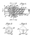
- Figure 1 is a side elevational view, partly in cross section, of a phase-adjustable coaxial cable connector according to one embodiment of the invention;
- Figure 2 is an elevational view taken along line 2-2 of Figure 1, and
- Figure 3 is an elevational view taken along line 3-3 of Figure 1.
- A phase-adjustable coaxial cable connector is provided in which the length of the phase path of the system can be adjusted without changing the length of the connector. More specifically, this is achieved by providing, in the connector, relatively rotatable means for controlling the phase-path length of the connector. These means are placed between a central contact element of the connector on one end and a central conductor of the coaxial cable on the other end.
- According to one embodiment of the invention, the phase-adjustable coaxial connector comprises a first connector cylinder which supports, through a dielectric body, a central contact pin element, and has a coupling element at one end and an open-circuit element on the end face at the other end, the above-mentioned open-circuit element being in electrical contact with the central contact pin element, and a second connector cylinder which is located adjacent to the first connector cylinder and maintained in electrical contact with the central conductor at its one end and with the contact element through engagement with the open-circuit element, and a holder which supports adjacent ends of both connector cylinders. In the above-described construction, the first and second connector cylinders are provided at their adjacent ends with characteristic-impedance-matching means.
- Because the coaxial cable connector of the present invention has a rotatable phase-path adjusting means installed between the central conductor of the coaxial cable and the central contact element, the connector eliminates the cable length cutting operation as the phase adjustment procedure.
- In other words, without change in the length of the connector, the adjustment can be easily performed by relative rotation of the connector parts.
- In accordance with the illustrated embodiment, the connector comprises a first cylinder which has at one end a coupling element and supports a central contact element, and at the other end face has an open-circuit element which is in electrical contact with the above-mentioned central contact element, and a second connector cylinder which supports the coaxial cable and also has a contact element which is in electrical contact with the central conductor of the cable. It is possible, in this construction, to perform microscopic adjustment of the phase-path length of the central conductor by turning the contact element with respect to the open-circuit element of the connector.
- Both connector cylinders are locked together by means of a holder.
- In the vicinity of the open-circuit element, or near the contact element of the connector cylinder, the connector is provided with a characteristic-impedance-matching conductor which is used for matching the value of characteristic impedance.
- By rotating two parts of the holder with respect to each other, it is possible to disconnect both connector cylinders. A coaxial cable is attached to the second connector cylinder. Both connector cylinders are brought in contact at their ends, and then both connector cylinders are locked by screwing together the parts of the holder.
- In the embodiment of the invention illustrated in the drawings, the phase-adjustable coaxial connector 1 has a
first connector cylinder 2 and asecond connector cylinder 3 which are held together by a two-part ring-shaped holder 4. -
First connector cylinder 2 has at one end a rotatable coupling element 6 which is fixed against axial movement by acotter ring 5. The coupling element 6 has afemale thread 7 on its inner side and a hexagonal configuration 8 on its outer side. It can be connected, for example, to an external electronic device. The coupling element is made of a conductive material and may have a conductive connection through external connecting means. - A central connecting
pin element 9, which is intended for electrical connection of a central conductor, is supported by said first connector cylinder through a dielectric body 10. - The other end of the
first connector cylinder 2 has a flange 11 on its end surface and is electrically connected to a characteristic-impedance-matchingconductor ring 12. The end face ofring 12 supports adielectric element 13 and an open-circuit element 14, which are located sequentially one after the other. Open-circuit element 14 is electrically connected tocentral connecting element 9, and may have a "G"-like configuration as shown in Figure 2. The "G"-like configuration is given only as an example, and that open circuit element may have any other suitable configuration, such as a spiral-shaped, star-shaped, flower-shaped, or a zigzag-shaped configuration. - A
second connector cylinder 3 contains acoaxial cable 17 which comprises acentral conductor 18 spaced from an outer conductive element or shield 22 by a body ofdielectric material 26.Second connector cylinder 3, which is located adjacent tofirst connector 2, has on its end face a disc-like dielectric element 15 and acontact element 16, the preferable shape of which is shown in Figure 3. At one of its ends, the above-mentionedcontact element 16 is in electrical contact with open-circuit element 14, while the other end ofelement 16 is in electrical contact with acentral conductor 18 ofcoaxial cable 17 supported bysecond connector cylinder 3. The back side of dielectric element 15 has a characteristic-impedance-matchingconductor 19, which is attached to a flange portion 20 ofsecond connector cylinder 3 and is maintained in electrical contact with the latter. - An outer sheath 21 is peeled from the front end of external conductive element 22 of
coaxial cable 17 and is then inserted in the above-mentionedsecond connector cylinder 3. A solder is introduced through a solder-supply opening 23, and external conductive shield element 22 is soldered tosecond connector cylinder 3. At the same time, permanent electrical contact is established between both parts through the soldering connection. In a similar manner,central conductor 18 is soldered to contactelement 16. A cable-supportingring 24 is then screwed on tosecond connector cylinder 3. As a result,coaxial cable 17 is firmly attached tosecond connector cylinder 3. -
First connector cylinder 2 andsecond connector cylinder 3, withcoaxial cable 17 attached thereto, are brought in contact at their adjacent ends and then fixed in this position by screwing together the threadedhalves 4A and 4B of holder 4. - The phase of
coaxial cable 17 can be measured by a pulse-passing method, after connecting one end of the coaxial cable to a phase-adjustable connector of the present invention, and connecting the other end of the coaxial cable to an oscilloscope. If the phase does not correspond to a required value, holder 4 is loosened,first connector cylinder 2 is turned with respect tosecond connector cylinder 3, so that open-circuit element 14 is turned with respect tocontact element 16. This will change the position of electrical contact between both elements, and thus will adjust the actual phase-path length of the central conductor of the cable. After adjustment, the value of the phase is measured for the second time. Thus the invention eliminates the necessity of cutting the end of the coaxial cable as a measure of its phase adjustment. The phase of the coaxial cable can be quickly and simply adjusted to a required permanent value. - The invention is not limited only to the above-described embodiment. For example, the elements of the holder can be interconnected permanently through a flat seam. Adjustment of relative positions between the open-circuit element and contact element, which are embedded into the end surfaces of respective disk-like dielectric bodies, can be controlled through a lever or a rotating knob. The central contact element can be made as a female element, and contact can be achieved through the use of a coupling other than the one shown.
- The use of the coaxial connector of the above-described construction provides the following advantages:
- (1) Because measurement of the phase can be performed with installation of the connectors at both ends of a coaxial cable, it is possible to measure the phase by a pulse-passing method. This will result in high accuracy of measurement and will provide a coaxial cable assembly with high accuracy of the phase.
- (2) The invention eliminates the cable cutting operation as a phase-adjustment procedure. As a result, the time and expense required for the manufacture of the coaxial cable assembly is reduced.
- (3) Elimination of the cable cutting operation as a phase-adjustment procedure eliminates problems which may occur in the case when the cable is cut shorter than the allowable limit.
- (4) The adjustment operation is very simple and does not require skilled labour.
- (5) Because the effective length of the conductor (phase-path length), i.e., the phase, is adjusted by relative rotation, it is not necessary to vary the length of the connector, to change the design of the instrument, or to restrict the degree of freedom in the connection.
Claims (5)
Priority Applications (1)
| Application Number | Priority Date | Filing Date | Title |
|---|---|---|---|
| AT87308366T ATE84644T1 (en) | 1986-10-03 | 1987-09-22 | COAXIAL CABLE CONNECTOR. |
Applications Claiming Priority (2)
| Application Number | Priority Date | Filing Date | Title |
|---|---|---|---|
| JP235840/86 | 1986-10-03 | ||
| JP61235840A JPS6391982A (en) | 1986-10-03 | 1986-10-03 | Phase adjusting coaxial connector |
Publications (3)
| Publication Number | Publication Date |
|---|---|
| EP0262851A2 true EP0262851A2 (en) | 1988-04-06 |
| EP0262851A3 EP0262851A3 (en) | 1988-10-05 |
| EP0262851B1 EP0262851B1 (en) | 1993-01-13 |
Family
ID=16992045
Family Applications (1)
| Application Number | Title | Priority Date | Filing Date |
|---|---|---|---|
| EP87308366A Expired - Lifetime EP0262851B1 (en) | 1986-10-03 | 1987-09-22 | A coaxial cable connector |
Country Status (9)
| Country | Link |
|---|---|
| US (1) | US4741702A (en) |
| EP (1) | EP0262851B1 (en) |
| JP (1) | JPS6391982A (en) |
| AT (1) | ATE84644T1 (en) |
| AU (1) | AU594274B2 (en) |
| DE (1) | DE3783550T2 (en) |
| GB (1) | GB2196490B (en) |
| HK (1) | HK102391A (en) |
| SG (1) | SG93291G (en) |
Cited By (2)
| Publication number | Priority date | Publication date | Assignee | Title |
|---|---|---|---|---|
| FR2643749A1 (en) * | 1989-02-23 | 1990-08-31 | Dx Antenna | DEVICE FOR COUPLING A HIGH FREQUENCY COAXIAL LINE |
| FR2950201A1 (en) * | 2009-09-11 | 2011-03-18 | Snecma | Electrical lead conductors connecting device for airplane engine, has electrical conductive slip ring mounted between tubular body and cylindrical sleeve to ensure electrical continuity between body and sleeve |
Families Citing this family (13)
| Publication number | Priority date | Publication date | Assignee | Title |
|---|---|---|---|---|
| JPS6391981A (en) * | 1986-10-03 | 1988-04-22 | 株式会社 潤工社 | Phase adjusting coaxial connector |
| FR2610454B1 (en) * | 1987-01-29 | 1989-06-09 | Technomed Int Sa | DEVICE PROVIDING IMPROVED ELECTRICAL CONTACT BETWEEN AN ELECTRICAL CONDUCTOR AND AN ELECTRODE OR AN ELECTRODE-HOLDING ELEMENT; USE OF THIS DEVICE IN ANY DEVICE FOR ADVANCING AN ELECTRODE OR AN ELECTRODE-HOLDING ELEMENT |
| US4954669A (en) * | 1989-01-25 | 1990-09-04 | W. L. Gore & Associates, Inc. | Coaxial cable connector assembly |
| US5152790A (en) * | 1991-03-21 | 1992-10-06 | American Cyanamid Company | Ligament reconstruction graft anchor apparatus |
| GB2306059A (en) * | 1995-06-01 | 1997-04-23 | Huber+Suhner Ag | Axially adjustable coaxial electrical connecting line with constant impedance |
| GB2315167B (en) * | 1996-07-08 | 1999-04-21 | Amphenol Corp | Electrical connector and cable termination system |
| FI101329B (en) * | 1996-08-29 | 1998-05-29 | Nokia Telecommunications Oy | A method for tuning a base station summation network |
| EP1182744B1 (en) * | 2000-08-19 | 2004-07-14 | Spinner GmbH Elektrotechnische Fabrik | Phase balancing means for a coaxial cable and connector therefore |
| US6667440B2 (en) * | 2002-03-06 | 2003-12-23 | Commscope Properties, Llc | Coaxial cable jumper assembly including plated outer conductor and associated methods |
| US6887102B1 (en) * | 2004-04-13 | 2005-05-03 | Corning Gilbert Inc. | Coaxial cable connector and nut member |
| US7883363B2 (en) * | 2009-06-05 | 2011-02-08 | John Mezzalingua Associates, Inc. | Phase adjustable adapter |
| KR101269374B1 (en) | 2012-03-13 | 2013-05-29 | 울산대학교 산학협력단 | High frequency connector assembly |
| KR20210043132A (en) | 2019-10-11 | 2021-04-21 | 삼성전자주식회사 | Cable Device |
Citations (3)
| Publication number | Priority date | Publication date | Assignee | Title |
|---|---|---|---|---|
| US3697930A (en) * | 1967-10-09 | 1972-10-10 | James W Shirey | Solderless coaxial connectors |
| EP0102166A1 (en) * | 1982-08-17 | 1984-03-07 | AMP INCORPORATED (a New Jersey corporation) | Method for terminating phase-matched semirigid coaxial cable |
| GB2157894A (en) * | 1984-04-24 | 1985-10-30 | Bertram Sykes | Improvements in or relating to aerial systems |
Family Cites Families (7)
| Publication number | Priority date | Publication date | Assignee | Title |
|---|---|---|---|---|
| US3408610A (en) * | 1967-04-10 | 1968-10-29 | Anthony T. Clarkson | Rotatable coaxial coupling |
| US3663901A (en) * | 1970-02-27 | 1972-05-16 | Amp Inc | Tuned coaxial device |
| US3904264A (en) * | 1974-03-04 | 1975-09-09 | Continental Oil Co | Electrical connector |
| JPS51145042A (en) * | 1975-06-06 | 1976-12-13 | Mitsubishi Electric Corp | Boiling type refrigeration system |
| US4110716A (en) * | 1976-11-01 | 1978-08-29 | Nikitas Nick C | D.C. block connectors |
| FR2545659B1 (en) * | 1983-05-04 | 1985-07-05 | Cables De Lyon Geoffroy Delore | CORE EXTENSION OF A COAXIAL CABLE, AND CONNECTOR PROVIDED WITH SUCH AN EXTENSION |
| JPS6391981A (en) * | 1986-10-03 | 1988-04-22 | 株式会社 潤工社 | Phase adjusting coaxial connector |
-
1986
- 1986-10-03 JP JP61235840A patent/JPS6391982A/en active Pending
-
1987
- 1987-08-31 US US07/091,644 patent/US4741702A/en not_active Expired - Fee Related
- 1987-09-10 AU AU78267/87A patent/AU594274B2/en not_active Ceased
- 1987-09-21 GB GB8722185A patent/GB2196490B/en not_active Expired - Fee Related
- 1987-09-22 DE DE8787308366T patent/DE3783550T2/en not_active Expired - Fee Related
- 1987-09-22 AT AT87308366T patent/ATE84644T1/en not_active IP Right Cessation
- 1987-09-22 EP EP87308366A patent/EP0262851B1/en not_active Expired - Lifetime
-
1991
- 1991-11-07 SG SG932/91A patent/SG93291G/en unknown
- 1991-12-12 HK HK1023/91A patent/HK102391A/en not_active IP Right Cessation
Patent Citations (3)
| Publication number | Priority date | Publication date | Assignee | Title |
|---|---|---|---|---|
| US3697930A (en) * | 1967-10-09 | 1972-10-10 | James W Shirey | Solderless coaxial connectors |
| EP0102166A1 (en) * | 1982-08-17 | 1984-03-07 | AMP INCORPORATED (a New Jersey corporation) | Method for terminating phase-matched semirigid coaxial cable |
| GB2157894A (en) * | 1984-04-24 | 1985-10-30 | Bertram Sykes | Improvements in or relating to aerial systems |
Cited By (2)
| Publication number | Priority date | Publication date | Assignee | Title |
|---|---|---|---|---|
| FR2643749A1 (en) * | 1989-02-23 | 1990-08-31 | Dx Antenna | DEVICE FOR COUPLING A HIGH FREQUENCY COAXIAL LINE |
| FR2950201A1 (en) * | 2009-09-11 | 2011-03-18 | Snecma | Electrical lead conductors connecting device for airplane engine, has electrical conductive slip ring mounted between tubular body and cylindrical sleeve to ensure electrical continuity between body and sleeve |
Also Published As
| Publication number | Publication date |
|---|---|
| SG93291G (en) | 1991-12-13 |
| DE3783550D1 (en) | 1993-02-25 |
| JPS6391982A (en) | 1988-04-22 |
| EP0262851B1 (en) | 1993-01-13 |
| GB2196490B (en) | 1990-06-20 |
| HK102391A (en) | 1991-12-20 |
| ATE84644T1 (en) | 1993-01-15 |
| US4741702A (en) | 1988-05-03 |
| EP0262851A3 (en) | 1988-10-05 |
| AU7826787A (en) | 1988-04-14 |
| DE3783550T2 (en) | 1993-07-29 |
| GB8722185D0 (en) | 1987-10-28 |
| GB2196490A (en) | 1988-04-27 |
| AU594274B2 (en) | 1990-03-01 |
Similar Documents
| Publication | Publication Date | Title |
|---|---|---|
| EP0262851A2 (en) | A coaxial cable connector | |
| US7488210B1 (en) | RF terminator | |
| CA1249350A (en) | High frequency connector | |
| CA2025609C (en) | Self-aligning rf push-on connector | |
| JP3058343B2 (en) | Electrical connector | |
| EP0262918B1 (en) | Phase-adjustable coaxial cable connector | |
| EP0561328B1 (en) | Connector assembly | |
| US6053743A (en) | Clip for surface mount termination of a coaxial cable | |
| EP0412412B1 (en) | Connector | |
| EP0351903A1 (en) | Dismountable coaxial coupling | |
| CA2255901A1 (en) | Coaxial cable connector | |
| US4556265A (en) | RF Coaxial-strip line connector | |
| KR20160131930A (en) | Terminal connection comprising an hf conductor, in particular for a coaxial cable, and method for producing said terminal connection | |
| US4707039A (en) | Coaxial connector for controlled impedance transmission lines | |
| EP0111162A1 (en) | Encapsulated, shielded, and grounded connector | |
| US4076367A (en) | Solderless connector | |
| EP1191655B1 (en) | A crimpless strain relief termination for a coaxial cable | |
| EP1642362B1 (en) | Coaxial connector | |
| US4779067A (en) | Microwave phase trimmer | |
| EP0372828A2 (en) | Microwave connector | |
| EP0311226B1 (en) | Coaxial cable connection assembly with a transceiver | |
| CA1115370A (en) | Connector plug for coaxial cables | |
| US5729184A (en) | Tap for extracting energy from transmission lines using impedance transformers | |
| JP3164803B1 (en) | Coaxial outlet | |
| US5435756A (en) | Adapter for two core cable |
Legal Events
| Date | Code | Title | Description |
|---|---|---|---|
| PUAI | Public reference made under article 153(3) epc to a published international application that has entered the european phase |
Free format text: ORIGINAL CODE: 0009012 |
|
| AK | Designated contracting states |
Kind code of ref document: A2 Designated state(s): AT BE CH DE ES FR GB GR IT LI LU NL SE |
|
| PUAL | Search report despatched |
Free format text: ORIGINAL CODE: 0009013 |
|
| AK | Designated contracting states |
Kind code of ref document: A3 Designated state(s): AT BE CH DE ES FR GB GR IT LI LU NL SE |
|
| 17P | Request for examination filed |
Effective date: 19890307 |
|
| 17Q | First examination report despatched |
Effective date: 19910723 |
|
| GRAA | (expected) grant |
Free format text: ORIGINAL CODE: 0009210 |
|
| AK | Designated contracting states |
Kind code of ref document: B1 Designated state(s): AT BE CH DE ES FR GB GR IT LI LU NL SE |
|
| PG25 | Lapsed in a contracting state [announced via postgrant information from national office to epo] |
Ref country code: NL Effective date: 19930113 Ref country code: LI Effective date: 19930113 Ref country code: GR Free format text: LAPSE BECAUSE OF FAILURE TO SUBMIT A TRANSLATION OF THE DESCRIPTION OR TO PAY THE FEE WITHIN THE PRESCRIBED TIME-LIMIT Effective date: 19930113 Ref country code: CH Effective date: 19930113 Ref country code: BE Effective date: 19930113 Ref country code: AT Effective date: 19930113 |
|
| REF | Corresponds to: |
Ref document number: 84644 Country of ref document: AT Date of ref document: 19930115 Kind code of ref document: T |
|
| ITF | It: translation for a ep patent filed |
Owner name: STUDIO TORTA SOCIETA' SEMPLICE |
|
| REF | Corresponds to: |
Ref document number: 3783550 Country of ref document: DE Date of ref document: 19930225 |
|
| ET | Fr: translation filed | ||
| PG25 | Lapsed in a contracting state [announced via postgrant information from national office to epo] |
Ref country code: ES Free format text: LAPSE BECAUSE OF FAILURE TO SUBMIT A TRANSLATION OF THE DESCRIPTION OR TO PAY THE FEE WITHIN THE PRESCRIBED TIME-LIMIT Effective date: 19930424 |
|
| REG | Reference to a national code |
Ref country code: CH Ref legal event code: PL |
|
| NLV1 | Nl: lapsed or annulled due to failure to fulfill the requirements of art. 29p and 29m of the patents act | ||
| PG25 | Lapsed in a contracting state [announced via postgrant information from national office to epo] |
Ref country code: LU Free format text: LAPSE BECAUSE OF NON-PAYMENT OF DUE FEES Effective date: 19930930 |
|
| PLBE | No opposition filed within time limit |
Free format text: ORIGINAL CODE: 0009261 |
|
| STAA | Information on the status of an ep patent application or granted ep patent |
Free format text: STATUS: NO OPPOSITION FILED WITHIN TIME LIMIT |
|
| 26N | No opposition filed | ||
| EAL | Se: european patent in force in sweden |
Ref document number: 87308366.1 |
|
| PGFP | Annual fee paid to national office [announced via postgrant information from national office to epo] |
Ref country code: FR Payment date: 19970820 Year of fee payment: 11 |
|
| PGFP | Annual fee paid to national office [announced via postgrant information from national office to epo] |
Ref country code: SE Payment date: 19970821 Year of fee payment: 11 |
|
| PGFP | Annual fee paid to national office [announced via postgrant information from national office to epo] |
Ref country code: DE Payment date: 19970822 Year of fee payment: 11 |
|
| PGFP | Annual fee paid to national office [announced via postgrant information from national office to epo] |
Ref country code: GB Payment date: 19970826 Year of fee payment: 11 |
|
| PG25 | Lapsed in a contracting state [announced via postgrant information from national office to epo] |
Ref country code: GB Free format text: LAPSE BECAUSE OF NON-PAYMENT OF DUE FEES Effective date: 19980922 |
|
| PG25 | Lapsed in a contracting state [announced via postgrant information from national office to epo] |
Ref country code: SE Free format text: LAPSE BECAUSE OF NON-PAYMENT OF DUE FEES Effective date: 19980923 |
|
| GBPC | Gb: european patent ceased through non-payment of renewal fee |
Effective date: 19980922 |
|
| EUG | Se: european patent has lapsed |
Ref document number: 87308366.1 |
|
| PG25 | Lapsed in a contracting state [announced via postgrant information from national office to epo] |
Ref country code: FR Free format text: LAPSE BECAUSE OF NON-PAYMENT OF DUE FEES Effective date: 19990531 |
|
| PG25 | Lapsed in a contracting state [announced via postgrant information from national office to epo] |
Ref country code: DE Free format text: LAPSE BECAUSE OF NON-PAYMENT OF DUE FEES Effective date: 19990701 |
|
| REG | Reference to a national code |
Ref country code: FR Ref legal event code: ST |
|
| PG25 | Lapsed in a contracting state [announced via postgrant information from national office to epo] |
Ref country code: IT Free format text: LAPSE BECAUSE OF NON-PAYMENT OF DUE FEES;WARNING: LAPSES OF ITALIAN PATENTS WITH EFFECTIVE DATE BEFORE 2007 MAY HAVE OCCURRED AT ANY TIME BEFORE 2007. THE CORRECT EFFECTIVE DATE MAY BE DIFFERENT FROM THE ONE RECORDED. Effective date: 20050922 |