EP0262239B1 - Breathing apparatus - Google Patents
Breathing apparatus Download PDFInfo
- Publication number
- EP0262239B1 EP0262239B1 EP86113343A EP86113343A EP0262239B1 EP 0262239 B1 EP0262239 B1 EP 0262239B1 EP 86113343 A EP86113343 A EP 86113343A EP 86113343 A EP86113343 A EP 86113343A EP 0262239 B1 EP0262239 B1 EP 0262239B1
- Authority
- EP
- European Patent Office
- Prior art keywords
- outlet
- inlet
- valve
- respiratory device
- pipe
- Prior art date
- Legal status (The legal status is an assumption and is not a legal conclusion. Google has not performed a legal analysis and makes no representation as to the accuracy of the status listed.)
- Expired - Lifetime
Links
- 230000029058 respiratory gaseous exchange Effects 0.000 title abstract description 20
- 239000000443 aerosol Substances 0.000 claims abstract description 9
- 238000002560 therapeutic procedure Methods 0.000 claims abstract description 6
- 230000001154 acute effect Effects 0.000 claims abstract description 3
- 230000000241 respiratory effect Effects 0.000 claims abstract 20
- 239000013013 elastic material Substances 0.000 claims description 3
- 238000007789 sealing Methods 0.000 claims description 2
- 238000004140 cleaning Methods 0.000 abstract description 4
- 230000000249 desinfective effect Effects 0.000 abstract 1
- 239000006199 nebulizer Substances 0.000 description 7
- 238000010276 construction Methods 0.000 description 3
- 238000004659 sterilization and disinfection Methods 0.000 description 3
- 238000011161 development Methods 0.000 description 2
- 230000018109 developmental process Effects 0.000 description 2
- 206010002091 Anaesthesia Diseases 0.000 description 1
- 208000031481 Pathologic Constriction Diseases 0.000 description 1
- 206010036790 Productive cough Diseases 0.000 description 1
- 230000037005 anaesthesia Effects 0.000 description 1
- 230000005540 biological transmission Effects 0.000 description 1
- 238000011109 contamination Methods 0.000 description 1
- 230000007547 defect Effects 0.000 description 1
- 201000010099 disease Diseases 0.000 description 1
- 208000037265 diseases, disorders, signs and symptoms Diseases 0.000 description 1
- 238000005516 engineering process Methods 0.000 description 1
- 230000002349 favourable effect Effects 0.000 description 1
- 238000004519 manufacturing process Methods 0.000 description 1
- 239000000203 mixture Substances 0.000 description 1
- 210000002345 respiratory system Anatomy 0.000 description 1
- 210000003802 sputum Anatomy 0.000 description 1
- 208000024794 sputum Diseases 0.000 description 1
- 230000036262 stenosis Effects 0.000 description 1
- 208000037804 stenosis Diseases 0.000 description 1
- 230000001225 therapeutic effect Effects 0.000 description 1
- 230000007704 transition Effects 0.000 description 1
Images
Classifications
-
- A—HUMAN NECESSITIES
- A61—MEDICAL OR VETERINARY SCIENCE; HYGIENE
- A61M—DEVICES FOR INTRODUCING MEDIA INTO, OR ONTO, THE BODY; DEVICES FOR TRANSDUCING BODY MEDIA OR FOR TAKING MEDIA FROM THE BODY; DEVICES FOR PRODUCING OR ENDING SLEEP OR STUPOR
- A61M16/00—Devices for influencing the respiratory system of patients by gas treatment, e.g. mouth-to-mouth respiration; Tracheal tubes
- A61M16/08—Bellows; Connecting tubes ; Water traps; Patient circuits
- A61M16/0816—Joints or connectors
- A61M16/0833—T- or Y-type connectors, e.g. Y-piece
-
- A—HUMAN NECESSITIES
- A61—MEDICAL OR VETERINARY SCIENCE; HYGIENE
- A61M—DEVICES FOR INTRODUCING MEDIA INTO, OR ONTO, THE BODY; DEVICES FOR TRANSDUCING BODY MEDIA OR FOR TAKING MEDIA FROM THE BODY; DEVICES FOR PRODUCING OR ENDING SLEEP OR STUPOR
- A61M16/00—Devices for influencing the respiratory system of patients by gas treatment, e.g. mouth-to-mouth respiration; Tracheal tubes
- A61M16/20—Valves specially adapted to medical respiratory devices
- A61M16/208—Non-controlled one-way valves, e.g. exhalation, check, pop-off non-rebreathing valves
-
- A—HUMAN NECESSITIES
- A63—SPORTS; GAMES; AMUSEMENTS
- A63B—APPARATUS FOR PHYSICAL TRAINING, GYMNASTICS, SWIMMING, CLIMBING, OR FENCING; BALL GAMES; TRAINING EQUIPMENT
- A63B23/00—Exercising apparatus specially adapted for particular parts of the body
- A63B23/18—Exercising apparatus specially adapted for particular parts of the body for improving respiratory function
-
- A—HUMAN NECESSITIES
- A61—MEDICAL OR VETERINARY SCIENCE; HYGIENE
- A61M—DEVICES FOR INTRODUCING MEDIA INTO, OR ONTO, THE BODY; DEVICES FOR TRANSDUCING BODY MEDIA OR FOR TAKING MEDIA FROM THE BODY; DEVICES FOR PRODUCING OR ENDING SLEEP OR STUPOR
- A61M15/00—Inhalators
Definitions
- the invention relates to a breathing device for controlled inhalation and exhalation for the purpose of therapy of the respiratory tract, comprising an inlet connection for air to be inhaled, an outlet connection for exhaled air, a connection connection which is connected to the inlet connection and the outlet connection, a one-way valve provided in the inlet connection formed inlet valve, which opens in the direction of the flow in the inlet port and blocks in the opposite direction, an exhalation resistance arranged on the outlet port, referred to in the art as a stenosis, against which the patient exhales, and an outlet valve arranged in the flow path of the outlet port, designed as a one-way valve, the opens in the direction of the flow in the outlet connection and blocks in the opposite direction, as a result of which inhalation of air through the exhalation resistance and the outlet connection is prevented.
- a breathing device of this type is known from US-A-4,210,174.
- the outlet valve is arranged in the outlet port and the exhalation resistance is designed in the form of a cone valve of complex construction.
- the invention has for its object to provide a breathing device of the type mentioned, in which the outlet valve and the exhalation resistance can be cleaned and disinfected with little effort before each patient change.
- the device according to the invention has the advantage that it has a surprisingly simple structure and enables the cleaning and disinfection of the outlet valve and breathing resistance in a simple and time-saving manner.
- a medical device for example an aerosol nebulizer
- the inlet valve and the outlet valve are advantageously designed to be removable. It is therefore easily possible to disassemble the device into its individual components in order to clean and disinfect it.
- the outlet valve and inlet valve advantageously each consist of a ring insert and a flap which is articulated on one side and seals against the end face of this ring insert.
- the flap is preferably made of flexible, in particular rubber-elastic material.
- the flap can be attached to the ring insert in the simplest way by means of one or more, preferably two, pins. If very high demands are made on the tightness of the valves, an additional sealing lip can be provided between the ring insert and the flap.
- Such one-way valves which are designed as separate structural units, can be manufactured easily and in large numbers in terms of production technology and can be inserted into the breathing apparatus in the simplest way. They can easily be replaced for cleaning and disinfection purposes or in the event of a defect.
- the exhalation resistance can be plugged onto the outlet connection.
- the outlet valve is then expediently inserted into the free end of the outlet nozzle. After removing the attached exhalation resistance from the outlet port, the outlet valve is freely accessible and can be easily removed. After the exhalation resistance is plugged in again, it is firmly fixed in its intended position.
- the inlet valve is preferably inserted into the free end of the inlet connector; the inlet valve, which is, for example, only clamped, can also be easily removed there.
- the exhalation resistance is designed as a stepped tube, the inner diameter of the tube section on the outlet side being substantially smaller than that of the outlet connector.
- the resulting narrowing of the cross-section in the direction of the air outlet results in the desired flow resistance against which the patient must exhale.
- the stepped pipe can be easily plugged onto the end of the outlet nozzle; the flow resistance can be selected by the choice of the inside diameter of the pipe section on the outlet side.
- the exhalation resistance can also be formed by means of adjustable blow-out openings through which the exhaled air is released.
- Inlet neck and outlet neck form an acute angle. At no point does the flowing air have to be redirected more than absolutely necessary, which not only avoids additional flow resistance, but also significantly reduces the risk of internal pollution of the device.
- the angle between the inlet connection and the outlet connection is preferably between 30 and 50 degrees.
- An embodiment is particularly advantageous in which a mouthpiece is attached to the connecting piece.
- This mouthpiece can also be easily removed so that the entire device can be disassembled into its individual parts and disinfected well.
- the adapter connection of an inflatable breathing mask can also be attached to the connecting piece.
- a breathing device equipped with such an additional connection is particularly predestined for the implementation of the double therapy described above.
- a closable opening can be provided, to which a pressure measuring device can be connected. This makes it possible to control the pressure exerted by the patient when exhaling during therapy.
- the breathing apparatus shown in Fig. 1 has an inlet port (1) for air to be inhaled, an outlet port (2) for exhaled air and a connecting piece (3) which is connected to the patient's airways.
- Inlet nozzle (1) and Outlet (2) open obliquely into the connecting piece (3), enclosing an angle of approximately 60 degrees.
- An exhalation resistor (4) is attached to the end of the outlet connection (2).
- an inlet valve (5) designed as a one-way valve is inserted.
- a one-way valve of the same construction is located as an outlet valve (6) in the outlet port (2) before the exhalation resistor (4).
- the outlet valve (6) is drawn out. It consists of a ring insert (7), on the end face (8) of which a flap (9) is articulated on one side.
- the flap (9) is made of rubber-elastic material and is attached to the end face (8) of the ring insert (7) by means of two pins (10).
- the ring insert (7) itself and the pins (10) are made of plastic.
- the flap (9) seals airtight against the flat end face (8).
- the flexible flap (9) lifts off into the position shown in FIG. 2, so that the valve opens.
- the inlet valve (5) is of the same type as the described outlet valve (6).
- the inlet valve (5) and the outlet valve (6) are both clamped within the inlet connector (1) and the outlet connector (2) (see Fig. 1), so that they can be easily replaced.
- the exhalation resistance (4) is formed by a short stepped tube (11).
- the inside diameter of the pipe section (12) on the outlet side of the pipe (11) is considerably smaller than that of the outlet connector (2). This narrowing of the cross section results in the desired flow resistance against which the patient must exhale.
- a mouthpiece (13) is inserted into the free end of the connecting piece (3).
- the inlet connection (1) has at its free end a detachable connection (14) to which an aerosol nebulizer (15) is connected. If the patient breathes in through the mouthpiece (13), only air or a mixture of air and aerosol from the aerosol nebulizer (15) passes through the opened inlet valve (5) into the inlet port (1) and from there into the connecting port (3).
- the outlet valve (6) in the outlet port (2) is closed, so that no secondary air can penetrate through the exhalation resistor (4). If the patient then exhales the used air, the direction of flow within the breathing device is reversed.
- the inlet valve (5) closes instantly, while the outlet valve (6) opens due to the pressure, so that the exhaled air can escape through the exhalation resistor (4).
- the aerosol nebulizer (15) is reliably protected by the closed inlet valve (5) against contamination by the humidified and possibly contaminated exhaled air.
- precisely defined flow conditions are established within the device in each phase.
- the pressure exerted by the patient during exhalation can be controlled by a pressure measuring device (not shown), which is provided via a closable opening (16) approximately in the area of the transition between the inlet connection (1) and the connection connection (3).
Landscapes
- Health & Medical Sciences (AREA)
- Pulmonology (AREA)
- General Health & Medical Sciences (AREA)
- Heart & Thoracic Surgery (AREA)
- Emergency Medicine (AREA)
- Engineering & Computer Science (AREA)
- Anesthesiology (AREA)
- Biomedical Technology (AREA)
- Hematology (AREA)
- Life Sciences & Earth Sciences (AREA)
- Animal Behavior & Ethology (AREA)
- Public Health (AREA)
- Veterinary Medicine (AREA)
- Physical Education & Sports Medicine (AREA)
- Respiratory Apparatuses And Protective Means (AREA)
- Measurement Of The Respiration, Hearing Ability, Form, And Blood Characteristics Of Living Organisms (AREA)
Abstract
Description
Die Erfindung betrifft eine Atemvorrichtung zum kontrollierten Ein- und Ausatmen zwecks Therapie der Atemwege, umfassend einen Einlaßstutzen für einzuatmende Luft, einen Auslaßstutzen für ausgeatmete Luft, einen Verbindungsstutzen, der mit dem Einlaßstutzen und dem Auslaßstutzen in Verbindung steht, ein im Einlaßstutzen vorgesehenes, als Einwegventil ausgebildetes Einlaßventil, das in Richtung der Strömung im Einlaßstutzen öffnet und in Gegenrichtung sperrt, einen am Auslaßstutzen angeordneten, in der Fachwelt auch als Stenose bezeichneten Ausatemwiderstand, gegen den der Patient ausatmet, und ein im Strömungsweg des Auslaßstutzens angeordnetes, als Einwegventil ausgebildetes Auslaßventil, das in Richtung der Strömung im Auslaßstutzen öffnet und in Gegenrichtung sperrt, wodurch ein Einatmen von Luft durch den Ausatemwiderstand und den Auslaßstutzen verhindert wird.The invention relates to a breathing device for controlled inhalation and exhalation for the purpose of therapy of the respiratory tract, comprising an inlet connection for air to be inhaled, an outlet connection for exhaled air, a connection connection which is connected to the inlet connection and the outlet connection, a one-way valve provided in the inlet connection formed inlet valve, which opens in the direction of the flow in the inlet port and blocks in the opposite direction, an exhalation resistance arranged on the outlet port, referred to in the art as a stenosis, against which the patient exhales, and an outlet valve arranged in the flow path of the outlet port, designed as a one-way valve, the opens in the direction of the flow in the outlet connection and blocks in the opposite direction, as a result of which inhalation of air through the exhalation resistance and the outlet connection is prevented.
Eine Atemvorrichtung dieser Art ist aus der Druckschrift US-A-4 210 174 bekannt. Bei der dort in Fig. 5 dargestellten Ausführungsform ist das Auslaßventil im Auslaßstutzen angeordnet und der Ausatemwiderstand in Form eines kompliziert aufgebauten Kegelventils ausgebildet.A breathing device of this type is known from US-A-4,210,174. In the embodiment shown there in FIG. 5, the outlet valve is arranged in the outlet port and the exhalation resistance is designed in the form of a cone valve of complex construction.
Da beim therapeutischen Einsatz von Atemvorrichtungen der eingangs genannten Art zwangsläufig Sputum des Patienten zum Auslaßventil und den Ausatemwiderstand gelangt, müssen diese Bauteile zur Vermeidung der Übertragung von Krankheiten vor jedem Patientenwechsel sorgfältig gereinigt und desinfiziert werden, wozu diese Bauelemente aus bzw. von der Vorrichtung entfernt werden müssen. Bei der vorbekannten Vorrichtung muß der Ausatemwiderstand aufgrund seiner komplizierten Konstruktion, welche Nischen und sonstige, von einer Spülung schwer erfaßbare Innenräume bildet, zur Reinigung und Desinfizierung praktisch zerlegt und anschließend wieder sorgfältig Zusammengesetzt werden, was einen erheblichen Einsatz von entsprechend geschultem Laborpersonal bedingt.Since the therapeutic use of breathing devices of the type mentioned inevitably leads to sputum of the patient at the outlet valve and the exhalation resistance, these components must be carefully cleaned and disinfected to avoid the transmission of diseases before each patient change, for which these components must be removed from or from the device. In the known device, the exhalation resistance, due to its complicated construction, which forms niches and other interiors that are difficult to detect by rinsing, has to be disassembled for cleaning and disinfection and then carefully reassembled, which requires considerable use by appropriately trained laboratory personnel.
Aus der Druckschrift US-A-4 111 228 ist eine Atemvorrichtung für die Anästhesie bekannt, bei welcher in einem Einlaßstutzen ein Einlaßventil und in einem Auslaßstutzen ein Auslaßventil vorgesehen sind. Ein Ausatemwiderstand ist bei dieser Vorrichtung nicht vorhanden.From US-A-4 111 228 a breathing apparatus for anesthesia is known in which an inlet valve is provided in an inlet nozzle and an outlet valve is provided in an outlet nozzle. There is no exhalation resistance in this device.
Der Erfindung liegt die Aufgabe zugrunde, eine Atemvorrichtung der eingangs genannten Art zu schaffen, bei welcher das Auslaßventil und der Ausatemwiderstand vor jedem Patientenwechsel mit geringem personellem Aufwand gereinigt und desinfiziert werden können.The invention has for its object to provide a breathing device of the type mentioned, in which the outlet valve and the exhalation resistance can be cleaned and disinfected with little effort before each patient change.
Erfindungsgemäß wird diese Aufgabe mit den Merkmalen des kennzeichnenden Teils des Patentanspruchs 1 gelöst.According to the invention, this object is achieved with the features of the characterizing part of patent claim 1.
Die erfindungsgemäße Vorrichtung weist den Vorteil auf, daß sie einen überraschend einfachen Aufbau besitzt und die Reinigung und Desinfektion von Auslaßventil und Atemwiderstand auf einfache und zeitsparende Weise ermöglicht.The device according to the invention has the advantage that it has a surprisingly simple structure and enables the cleaning and disinfection of the outlet valve and breathing resistance in a simple and time-saving manner.
Weiterbildungen der Erfindung ergeben sich aus den dem Patentanspruch 1 nachgeordneten Unteransprüchen.Further developments of the invention result from the subordinate claims subordinate to patent claim 1.
An den Einlaßstutzen der erfindungsgemäßen Vorrichtung läßt sich problemlos ein medizin-technisches Gerät, beispielsweise ein Aerosol-Vernebler, anschließen. Dabei kann gewährleistet werden, daß die vom Patienten eingeatmete Luft ausschließlich aus dem Vernebelungsgerät stammt und keine Nebenluft unkontrolliert zuströmt. Dabei können gleichzeitig, d. h. während einer einzigen Behandlungssitzung, sowohl eine Atemtherapie als auch eine atemunterstützende Inhalationsbehandlung durchgeführt werden.A medical device, for example an aerosol nebulizer, can be easily connected to the inlet port of the device according to the invention. It can be ensured that the air inhaled by the patient comes exclusively from the nebulizer and that no secondary air flows in uncontrollably. At the same time, d. H. Both breathing therapy and breathing support inhalation treatment are performed during a single treatment session.
Vorteilhaft sind das Einlaßventil und das Auslaßventil demontierbar ausgebildet. Es ist deshalb leicht möglich, das Gerät in seine Einzelbestandteile zu zerlegen, um es zu reinigen und zu desinfizieren.The inlet valve and the outlet valve are advantageously designed to be removable. It is therefore easily possible to disassemble the device into its individual components in order to clean and disinfect it.
Vorteilhaft bestehen Auslaßventil und Einlaßventil jeweils aus einem Ringeinsatz und einer gegen die Stirnseite dieses Ringeinsatzes abdichtenden, einseitig angelenkten Klappe. Bevorzugt besteht die Klappe aus flexiblem, insbesondere gummielastischen Material. Die Klappe kann auf einfachste Weise mittels einer oder mehrerer, vorzugsweise zwei Stiften auf dem Ringeinsatz befestigt sein. Bei sehr hohen Ansprüchen an die erzielbare Dichtigkeit der Ventile kann eine zusätzliche Dichtlippe zwischen Ringeinsatz und Klappe vorgesehen sein. Solche, als separate Baueinheit ausgebildete Einwegventile lassen sich fertigungstechnisch leicht und in großen Stückzahlen herstellen und sind auf einfachste Weise in die Atemvorrichtung einsetzbar. Zu Reinigungs- und Desinfektionszwecken oder im Falle eines Defektes lassen sie sich leicht austauschen.The outlet valve and inlet valve advantageously each consist of a ring insert and a flap which is articulated on one side and seals against the end face of this ring insert. The flap is preferably made of flexible, in particular rubber-elastic material. The flap can be attached to the ring insert in the simplest way by means of one or more, preferably two, pins. If very high demands are made on the tightness of the valves, an additional sealing lip can be provided between the ring insert and the flap. Such one-way valves, which are designed as separate structural units, can be manufactured easily and in large numbers in terms of production technology and can be inserted into the breathing apparatus in the simplest way. They can easily be replaced for cleaning and disinfection purposes or in the event of a defect.
In zweckmäßiger Weiterbildung der Erfindung ist der Ausatemwiderstand auf den Auslaßstutzen aufsteckbar. Das Auslaßventil ist dann zweckmäßigerweise in das freie Ende des Auslaßstutzens eingesetzt. Nach Abziehen des aufgesteckten Ausatemwiderstands vom Auslaßstutzen wird so das Auslaßventil frei zugänglich und läßt sich leicht herausnehmen. Nach dem Wiederaufstecken des Ausatemwiderstands ist es fest in seiner vorgesehenen Lage fixiert.In an expedient development of the invention, the exhalation resistance can be plugged onto the outlet connection. The outlet valve is then expediently inserted into the free end of the outlet nozzle. After removing the attached exhalation resistance from the outlet port, the outlet valve is freely accessible and can be easily removed. After the exhalation resistance is plugged in again, it is firmly fixed in its intended position.
Das Einlaßventil ist vorzugsweise in das freie Ende des Einlaßstutzens eingesetzt; das beispielsweise lediglich klemmend befestigte Einlaßventil läßt sich dort ebenfalls gut demontieren.The inlet valve is preferably inserted into the free end of the inlet connector; the inlet valve, which is, for example, only clamped, can also be easily removed there.
Bei der erfindungsgemäßen Atemvorrichtung ist der Ausatemwiderstand als abgestuftes Rohr ausgebildet, wobei der Innendurchmesser des auslaßseitigen Rohrabschnitts wesentlich kleiner ist als derjenige des Auslaßstutzens. Die sich hierdurch ergebende Querschnittsverengung in Richtung des Luftauslasses ergibt den gewünschten Strömungswiderstand, gegen den der Patient ausatmen muß. Das abgestufte Rohr läßt sich gut auf das Ende des Auslaßstutzens aufstecken; der Strömungswiderstand ist durch die Wahl des Innendurchmessers des auslaßseitigen Rohrabschnitts wählbar. Der Ausatemwiderstand kann aber auch mittels einstellbarer Ausblasöffnungen, durch welche die ausgeatmete Luft ins Freie gelangt, gebildet werden.In the breathing device according to the invention, the exhalation resistance is designed as a stepped tube, the inner diameter of the tube section on the outlet side being substantially smaller than that of the outlet connector. The resulting narrowing of the cross-section in the direction of the air outlet results in the desired flow resistance against which the patient must exhale. The stepped pipe can be easily plugged onto the end of the outlet nozzle; the flow resistance can be selected by the choice of the inside diameter of the pipe section on the outlet side. The exhalation resistance can also be formed by means of adjustable blow-out openings through which the exhaled air is released.
Besonders günstige Strömungsverhältnisse ergeben sich, wenn Einlaßstutzen und Auslaßstutzen gleichsinnig schräg in den Verbindungsstutzen einmünden. Einlaßstutzen und Auslaßstutzen bilden dabei einen spitzen Winkel. An keiner Stelle muß die strömende Luft mehr als unbedingt notwendig umgelenkt werden, wodurch nicht nur zusätzliche Strömungswiderstände vermieden werden, sondern auch die Gefahr der inneren Verschmutzung des Gerätes wesentlich herabgesetzt ist. Vorzugsweise beträgt der Winkel zwischen Einlaßstutzen und Auslaßstutzen zwischen 30 und 50 Winkelgraden.Particularly favorable flow conditions result when the inlet connector and outlet connector open in the same direction at an angle into the connection connector. Inlet neck and outlet neck form an acute angle. At no point does the flowing air have to be redirected more than absolutely necessary, which not only avoids additional flow resistance, but also significantly reduces the risk of internal pollution of the device. The angle between the inlet connection and the outlet connection is preferably between 30 and 50 degrees.
Besonders vorteilhaft ist eine Ausführungsform, bei der auf den Verbindunsstutzen ein Mundstück aufgesteckt ist. Dieses Mundstück läßt sich ebenfalls leicht abziehen, so daß sich das gesamte Gerät in seine Einzelteile zerlegen und gut desinfizieren läßt. Anstelle des Mundstücks kann auch der Adapteranschluß einer aufblasbaren Atemmaske an den Verbindungsstutzen angesteckt werden.An embodiment is particularly advantageous in which a mouthpiece is attached to the connecting piece. This mouthpiece can also be easily removed so that the entire device can be disassembled into its individual parts and disinfected well. Instead of the mouthpiece, the adapter connection of an inflatable breathing mask can also be attached to the connecting piece.
Der mögliche Anschluß eines medizintechnischen Geräts, insbesondere eines Aerosol-Vernebelungsgerätes, wird erleichtert, wenn der Einlaßstutzen an seinem freien Ende einen speziell dafür vorgesehenen, lösbaren Anschluß aufweist. Eine mit einem solchen zusätzlichen Anschluß ausgerüstete Atemvorrichtung ist besonders für die Durchführung der oben beschriebenen Doppeltherapie prädestiniert.The possible connection of a medical device, in particular an aerosol nebulizer, is facilitated if the inlet connector has a detachable connection provided at its free end. A breathing device equipped with such an additional connection is particularly predestined for the implementation of the double therapy described above.
Schließlich kann eine verschließbare Öffnung vorgesehen sein, an welche eine Druckmeßvorrichtung anschließbar ist. Auf diese Weise wird eine Kontrolle des vom Patienten aufgebrachten Drucks beim Ausatmen während der Therapie ermöglicht.Finally, a closable opening can be provided, to which a pressure measuring device can be connected. This makes it possible to control the pressure exerted by the patient when exhaling during therapy.
Ein Ausführungsbeispiel der Erfindung wird nachstehend anhand der beigefügten Zeichnungen näher erläutert. Es zeigen:
- Fig. 1:
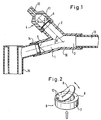
- eine Atemvorrichtung gemäß der Erfindung, mit aufgestecktem, rohrabschnittsförmigen Ausatemwiderstand, aufgestecktem Mundstück und an den Einlaßstutzen angeschlossenem Aerosol-Vernebler, in einem Schnittbild; und
- Fig. 2:
- das in die Atemvorrichtung gemäß Fig. 1 eingesetzte Auslaßventil, in einer vergrößerten perspektivischen Darstellung.
- Fig. 1:
- a breathing device according to the invention, with attached, tubular section-shaped exhalation resistance, attached mouthpiece and connected to the inlet port aerosol nebulizer, in a sectional view; and
- Fig. 2:
- the exhaust valve used in the breathing apparatus of FIG. 1, in an enlarged perspective view.
Die in Fig. 1 dargestellte Atemvorrichtung besitzt einen Einlaßstutzen (1) für einzuatmende Luft, einen Auslaßstutzen (2) für ausgeatmete Luft sowie einen Verbindungsstutzen (3), der mit den Atemwegen des Patienten in Verbindung steht. Einlaßstutzen (1) und Auslaßstutzen (2) münden schräg in den Verbindungsstutzen (3) ein, wobei sie einen Winkel von ungefähr 60 Winkelgraden einschließen. Auf das Ende des Auslaßstutzens (2) ist ein Ausatemwiderstand (4) aufgesteckt. Am freien Ende des Einlaßstutzens (1) ist ein als Einwegventil ausgebildetes Einlaßventil (5) eingesetzt. Ein Einwegventil gleicher Konstruktion befindet sich als Auslaßventil (6) im Auslaßstutzen (2) vor dem Ausatemwiderstand (4).The breathing apparatus shown in Fig. 1 has an inlet port (1) for air to be inhaled, an outlet port (2) for exhaled air and a connecting piece (3) which is connected to the patient's airways. Inlet nozzle (1) and Outlet (2) open obliquely into the connecting piece (3), enclosing an angle of approximately 60 degrees. An exhalation resistor (4) is attached to the end of the outlet connection (2). At the free end of the inlet connector (1), an inlet valve (5) designed as a one-way valve is inserted. A one-way valve of the same construction is located as an outlet valve (6) in the outlet port (2) before the exhalation resistor (4).
In Fig. 2 ist das Auslaßventil (6) herausgezeichnet. Es besteht aus einem Ringeinsatz (7), auf dessen Stirnseite (8) eine Klappe (9) einseitig angelenkt ist. Die Klappe (9) besteht aus gummielastischem Material und ist mittels zweier Stifte (10) auf der Stirnseite (8) des Ringeinsatzes (7) befestigt. Der Ringeinsatz (7) selbst sowie die Stifte (10) bestehen aus Kunststoff. In geschlossenem Zustand dichtet die Klappe (9) luftdicht gegenüber der ebenen Stirnseite (8) ab. Bei Durchströmung in Pfeilrichtung von unten nach oben hebt die flexible Klappe (9) in die in Fig. 2 gezeigte Stellung ab, so daß das Ventil öffnet. - Das Einlaßventil (5) ist von derselben Art wie das beschriebene Auslaßventil (6).In Fig. 2, the outlet valve (6) is drawn out. It consists of a ring insert (7), on the end face (8) of which a flap (9) is articulated on one side. The flap (9) is made of rubber-elastic material and is attached to the end face (8) of the ring insert (7) by means of two pins (10). The ring insert (7) itself and the pins (10) are made of plastic. In the closed state, the flap (9) seals airtight against the flat end face (8). When flowing in the direction of the arrow from bottom to top, the flexible flap (9) lifts off into the position shown in FIG. 2, so that the valve opens. - The inlet valve (5) is of the same type as the described outlet valve (6).
Das Einlaßventil (5) und das Auslaßventil (6) sind beide klemmend innerhalb des Einlaßstutzens (1) bzw. des Auslaßstutzens (2) befestigt (vgl. Fig. 1), so daß sie sich leicht austauschen lassen. Der Ausatmenwiderstand (4) wird gebildet von einem kurzen abgestuften Rohr (11). Der Innendurchmesser des auslaßseitigen Rohrabschnitts (12) des Rohres (11) ist wesentlich kleiner als derjenige des Auslaßstutzens (2). Durch diese Querschnittsverengung ergibt sich der gewünschte Strömungswiderstand, gegen den der Patient ausatmen muß.The inlet valve (5) and the outlet valve (6) are both clamped within the inlet connector (1) and the outlet connector (2) (see Fig. 1), so that they can be easily replaced. The exhalation resistance (4) is formed by a short stepped tube (11). The inside diameter of the pipe section (12) on the outlet side of the pipe (11) is considerably smaller than that of the outlet connector (2). This narrowing of the cross section results in the desired flow resistance against which the patient must exhale.
In das freie Ende des Verbindungsstutzens (3) ist ein Mundstück (13) eingesetzt. Der Einlaßstutzen (1) weist an seinem freien Ende einen lösbaren Anschluß (14) auf, an den ein Aerosol-Vernebelungsgerät (15) angeschlossen ist. Atmet nun der Patient über das Mundstück (13) ein, so gelangt ausschließlich Luft bzw. ein Gemisch aus Luft und Aerosol vom Aerosol-Vernebelungsgerät (15) durch das geöffnete Einlaßventil (5) in den Einlaßstutzen (1) und von da in den Verbindungsstutzen (3). Das Auslaßventil (6) im Auslaßstutzen (2) ist dagegen geschlossen, so daß keinerlei Nebenluft durch den Ausatemwiderstand (4) eindringen kann. Atmet der Patient anschließend die verbrauchte Luft aus, so kehrt sich die Strömungsrichtung innerhalb der Atemvorrichtung um. Das Einlaßventil (5) schließt augenblicklich, während das Auslaßventil (6) infolge des ein wirkenden Druckes öffnet, so daß die ausgeatmete Luft durch den Ausatemwiderstand (4) ins Freie gelangen kann. Das Aerosol-Vernebelungsgerät (15) wird dabei durch das geschlossene Einlaßventil (5) zuverlässig vor Verschmutzung durch die angefeuchtete und möglicherweise mit Krankheitskeimen beladene Ausatemluft geschützt. Infolge des wechselseitigen Öffnens und Schließens des Einlaßventils (5) bzw. des Auslaßventils (6) stellen sich in jeder Phase genau definierte Strömungsverhältnisse innerhalb des Geräts ein. Der vom Patienten aufgebrachte Druck während des Ausatmens kann durch eine (nicht dargestellte) Druckmeßvorrichtung kontrolliert werden, welche über eine verschließbare Öffnung (16) etwa im Bereich des Übergangs zwischen Einlaßstutzen (1) und Verbindungsstutzen (3) vorgesehen ist.A mouthpiece (13) is inserted into the free end of the connecting piece (3). The inlet connection (1) has at its free end a detachable connection (14) to which an aerosol nebulizer (15) is connected. If the patient breathes in through the mouthpiece (13), only air or a mixture of air and aerosol from the aerosol nebulizer (15) passes through the opened inlet valve (5) into the inlet port (1) and from there into the connecting port (3). The outlet valve (6) in the outlet port (2), on the other hand, is closed, so that no secondary air can penetrate through the exhalation resistor (4). If the patient then exhales the used air, the direction of flow within the breathing device is reversed. The inlet valve (5) closes instantly, while the outlet valve (6) opens due to the pressure, so that the exhaled air can escape through the exhalation resistor (4). The aerosol nebulizer (15) is reliably protected by the closed inlet valve (5) against contamination by the humidified and possibly contaminated exhaled air. As a result of the reciprocal opening and closing of the inlet valve (5) and the outlet valve (6), precisely defined flow conditions are established within the device in each phase. The pressure exerted by the patient during exhalation can be controlled by a pressure measuring device (not shown), which is provided via a closable opening (16) approximately in the area of the transition between the inlet connection (1) and the connection connection (3).
Claims (18)
- A respiratory device for monitored inhalation and exhalation for the purpose of respiratory duct therapy, comprising- an inlet pipe (1) for air to be inhaled,- an outlet pipe (2) for exhaled air,- a connection pipe (3) which is connected to the inlet pipe (1) and the outlet pipe (2),- an inlet valve (5) which is arranged in the inlet pipe (1), has the form of a one-way valve, and opens in the direction of the flow in the inlet pipe (1) and closes in the opposite direction,- an exhalation resistance (4) which is arranged on the outlet pipe (2) and against which the patient exhales and- an outlet valve (6) which is arranged in the flow path of the outlet pipe (2), has the form of a one-way valve, and opens in the direction of the flow in the outlet pipe (2) and closes in the opposite direction,- whereby inhalation of air through the exhalation resistance (4) and the outlet pipe (2) is prevented,
characterised in that- the outlet valve (6) is arranged on the outlet pipe (2) and- the exhalation resistance has the form of a stepped tube (11), where the inner diameter of the outlet-end tube segment (12) is substantially smaller than that of the outlet pipe (2). - A respiratory device as claimed in Claim 1, characterised in that the exhalation resistance (4) comprises adjustable outlet openings.
- A respiratory device as claimed in Claim 1 or 2, characterised in that the exhalation resistance (4) can be attached to the outlet pipe (2).
- A respiratory device as claimed in one of the preceding claims, characterised in that the outlet valve (6) is inserted into the free end of the outlet pipe (2).
- A respiratory device as claimed in one of the preceding claims, characterised in that the inlet valve (6) is inserted into the free end of the inlet pipe (1).
- A respiratory device as claimed in one of the preceding claims, characterised in that the outlet valve (6) and/or the inlet valve (5) are detachable.
- A respiratory device as claimed in one of the preceding claims, characterised in that the outlet valve (6) and/or the inlet valve (5) are composed of an annular insert (7) and a flap (9) which forms a seal with the end side (8) of this annular insert (7) and is articulated on one side.
- A respiratory device as claimed in Claim 7, characterised in that the flap (9) is composed of flexible, in particular rubber-elastic material.
- A respiratory device as claimed in Claim 7 or 8, characterised in that the flap (9) is fixed on the annular insert (7) by means of one or more, in particular two, pins (10).
- A respiratory device as claimed in one of Claims 7 to 9, characterised in that an additional sealing lip (7) is arranged between the annular insert (7) and the flap (9).
- A respiratory device as claimed in one of Claims 7 to 10, characterised in that the inlet valve (5) and the outlet valve (6) are attached by clamping inside the inlet pipe (1) and outlet pipe (2) respectively in such manner that they are exchangeable.
- A respiratory device as claimed in one of the preceding claims, characterised in that at its free end the inlet pipe (1) comprises a detachable terminal (14) for a medical device (15) in particular in the form of an aerosol atomizer.
- A respiratory device as claimed in Claims 7 and 12, characterised in that the annular insert (7) of the inlet valve (5) and a tubular segment of the medical device (15) can be inserted into the free end of the inlet pipe (1).
- A respiratory device as claimed in one of the preceding claims, characterised in that the inlet pipe (1) and the outlet pipe (2) lead obliquely and in the same direction into the connection pipe (3).
- A respiratory device as claimed in Claim 14, characterised in that the inlet pipe (1) and the outlet pipe (2) form an acute angle.
- A respiratory device as claimed in Claim 15, characterised in that the angle amounts to between 40° and 70°.
- A respiratory device as claimed in one of the preceding claims, characterised in that a mouth-piece (13) is attached to the connection pipe (3).
- A respiratory device as claimed in one of the preceding claims, characterised in that a closeable opening (16) is provided for the connection of a pressure measuring device.
Priority Applications (4)
| Application Number | Priority Date | Filing Date | Title |
|---|---|---|---|
| EP86113343A EP0262239B1 (en) | 1986-09-29 | 1986-09-29 | Breathing apparatus |
| AT86113343T ATE83939T1 (en) | 1986-09-29 | 1986-09-29 | BREATHING DEVICE. |
| DE8686113343T DE3687417D1 (en) | 1986-09-29 | 1986-09-29 | BREATHING DEVICE. |
| DE8625936U DE8625936U1 (en) | 1986-09-29 | 1986-09-29 | Breathing device |
Applications Claiming Priority (1)
| Application Number | Priority Date | Filing Date | Title |
|---|---|---|---|
| EP86113343A EP0262239B1 (en) | 1986-09-29 | 1986-09-29 | Breathing apparatus |
Publications (2)
| Publication Number | Publication Date |
|---|---|
| EP0262239A1 EP0262239A1 (en) | 1988-04-06 |
| EP0262239B1 true EP0262239B1 (en) | 1992-12-30 |
Family
ID=8195457
Family Applications (1)
| Application Number | Title | Priority Date | Filing Date |
|---|---|---|---|
| EP86113343A Expired - Lifetime EP0262239B1 (en) | 1986-09-29 | 1986-09-29 | Breathing apparatus |
Country Status (3)
| Country | Link |
|---|---|
| EP (1) | EP0262239B1 (en) |
| AT (1) | ATE83939T1 (en) |
| DE (2) | DE3687417D1 (en) |
Cited By (1)
| Publication number | Priority date | Publication date | Assignee | Title |
|---|---|---|---|---|
| US9179691B2 (en) | 2007-12-14 | 2015-11-10 | Aerodesigns, Inc. | Delivering aerosolizable food products |
Families Citing this family (17)
| Publication number | Priority date | Publication date | Assignee | Title |
|---|---|---|---|---|
| EP0281650B1 (en) * | 1987-03-10 | 1992-03-04 | Brugger, Stephan, Dipl.-Wirt.-Ing. | Aerosol sprayer |
| ATE89483T1 (en) * | 1987-08-14 | 1993-06-15 | Raupach Udo | RESPIRATORY THERAPY DEVICE. |
| US5018517A (en) * | 1987-10-22 | 1991-05-28 | Claude Liardet | Expiration-resisting apparatus designed for improving pulmonary ventilation |
| DE9304771U1 (en) * | 1993-03-29 | 1993-05-19 | Kendall-Medizinische Erzeugnisse - GmbH, 8425 Neustadt | Liquid nebulizer for medication |
| AU1868999A (en) * | 1998-06-28 | 2000-01-17 | Alfred Enzinger | Device for removing sputum from a tracheal catheter |
| ITPI20020018A1 (en) * | 2002-03-28 | 2002-06-26 | Azienda Ospedaliera Pisana | FLOW VARIATION PULMONARY VENTILATION |
| DE102011011874A1 (en) * | 2011-02-21 | 2012-08-23 | R. Cegla Gmbh & Co. Kg | therapy device |
| WO2015016890A1 (en) * | 2013-07-31 | 2015-02-05 | Berendo Scientific, LLC | Head and neck exercise apparatuses |
| US10335635B2 (en) | 2013-07-31 | 2019-07-02 | Berendo Scientific, LLC | Head and neck exercise methods |
| CN110787426B (en) * | 2019-11-08 | 2021-02-05 | 中国人民解放军陆军军医大学第二附属医院 | Breathing training device |
| CN111388812A (en) * | 2020-03-25 | 2020-07-10 | 中国人民解放军第四军医大学 | Integrative device of disinfection is collected to aerosol suitable for new coronavirus patient atomizing |
| EP3954418A1 (en) | 2020-08-11 | 2022-02-16 | CEGLA Medizintechnik GmbH & Co. KG | Respiratory therapy apparatus |
| US11717631B2 (en) * | 2020-11-04 | 2023-08-08 | Adel Bougatef | Ventilation system with three-port volume regulator |
| CN112619069B (en) * | 2020-12-16 | 2022-04-22 | 无锡市儿童医院 | Child breathes trainer |
| CN113244582B (en) * | 2021-05-17 | 2022-05-03 | 河北省胸科医院 | Department of respiration is with breathing trainer |
| CN113893503B (en) * | 2021-11-16 | 2022-08-09 | 中国人民解放军陆军军医大学第二附属医院 | Lung rehabilitation breathing training device |
| CN115999125B (en) * | 2023-01-03 | 2024-07-09 | 中国人民解放军西部战区总医院 | Respiratory exercise device for slow-resistance lung |
Family Cites Families (4)
| Publication number | Priority date | Publication date | Assignee | Title |
|---|---|---|---|---|
| US4111228A (en) * | 1975-07-23 | 1978-09-05 | Institutul Oncologic Bucuresti | Respiratory valve, especially for anaesthetic circuits |
| FI56120C (en) * | 1978-04-18 | 1979-12-10 | Taisto Haekkinen | VALVE AVSEDD FOER RESPIRATOR ELLER FOER ANNAN UPPLIVNINGSANVAENDNING LAEMPAD ANORDNING |
| US4210174A (en) * | 1978-05-30 | 1980-07-01 | Instrumentation Industries, Inc. | Positive pressure valves |
| FR2573658B1 (en) * | 1984-11-26 | 1989-02-24 | Air Liquide | POSITIVE EXPIRATORY PRESSURE DEVICE |
-
1986
- 1986-09-29 DE DE8686113343T patent/DE3687417D1/en not_active Expired - Fee Related
- 1986-09-29 DE DE8625936U patent/DE8625936U1/en not_active Expired
- 1986-09-29 EP EP86113343A patent/EP0262239B1/en not_active Expired - Lifetime
- 1986-09-29 AT AT86113343T patent/ATE83939T1/en not_active IP Right Cessation
Cited By (1)
| Publication number | Priority date | Publication date | Assignee | Title |
|---|---|---|---|---|
| US9179691B2 (en) | 2007-12-14 | 2015-11-10 | Aerodesigns, Inc. | Delivering aerosolizable food products |
Also Published As
| Publication number | Publication date |
|---|---|
| DE8625936U1 (en) | 1986-11-06 |
| ATE83939T1 (en) | 1993-01-15 |
| DE3687417D1 (en) | 1993-02-11 |
| EP0262239A1 (en) | 1988-04-06 |
Similar Documents
| Publication | Publication Date | Title |
|---|---|---|
| EP0262239B1 (en) | Breathing apparatus | |
| DE2847681C2 (en) | Tracheal tube | |
| DE3900183C2 (en) | ||
| EP1960025B1 (en) | Flexible conduit system for respiratory devices | |
| DE60106837T2 (en) | HME bypass system | |
| EP0281650B1 (en) | Aerosol sprayer | |
| DE2453490A1 (en) | PIPING SYSTEM OF A BREATHING DEVICE | |
| DE1616422B1 (en) | Valve for resuscitation apparatus | |
| EP1670530A1 (en) | Inhalation therapy device comprising a valve | |
| EP1695730A1 (en) | Component for an inhalation device and an inhalation device with this component | |
| DE2505123A1 (en) | Flexible plastics endotracheal tube - with speech valve pivotable at will between speaking and breathing positions | |
| EP1897577A1 (en) | Continuous positive airway pressure device (CPAP-device) | |
| DE20206692U1 (en) | Device for generating a continuous positive airway pressure (CPAP device) and corresponding hollow body | |
| DE19757703C1 (en) | Breathing mask with hose and enriched-air outlet | |
| DE202015100434U1 (en) | oxygen mask | |
| EP1095269B1 (en) | Device for determining the content of carbon dioxide in exhaled air | |
| DE8703534U1 (en) | Aerosol atomizer | |
| DE3513628C1 (en) | Device for the inhalation of allergens | |
| DE102012002632B4 (en) | Ventilation system and connector system for this to reduce contamination | |
| EP3620195B1 (en) | Ventilation device | |
| DE1248230B (en) | Tracheostomy tubes | |
| DE60206165T2 (en) | Handpiece of an inhaler | |
| DE1915540B2 (en) | Face mask esp. for lung function testing - has inhalation and exhalation valves with pneumo-tachograph tube and exhaled air collector | |
| DE19546167A1 (en) | Emergency breathing respirator apparatus | |
| DD284810A5 (en) | UNIT AND OUTDOOR UNIT FOR AN AEROSOLGERAET |
Legal Events
| Date | Code | Title | Description |
|---|---|---|---|
| PUAI | Public reference made under article 153(3) epc to a published international application that has entered the european phase |
Free format text: ORIGINAL CODE: 0009012 |
|
| AK | Designated contracting states |
Kind code of ref document: A1 Designated state(s): AT BE CH DE FR GB IT LI LU NL SE |
|
| 17P | Request for examination filed |
Effective date: 19880621 |
|
| 17Q | First examination report despatched |
Effective date: 19900523 |
|
| GRAA | (expected) grant |
Free format text: ORIGINAL CODE: 0009210 |
|
| AK | Designated contracting states |
Kind code of ref document: B1 Designated state(s): AT BE CH DE FR GB IT LI LU NL SE |
|
| ITF | It: translation for a ep patent filed | ||
| REF | Corresponds to: |
Ref document number: 83939 Country of ref document: AT Date of ref document: 19930115 Kind code of ref document: T |
|
| REF | Corresponds to: |
Ref document number: 3687417 Country of ref document: DE Date of ref document: 19930211 |
|
| ET | Fr: translation filed | ||
| GBT | Gb: translation of ep patent filed (gb section 77(6)(a)/1977) |
Effective date: 19920205 |
|
| PLBE | No opposition filed within time limit |
Free format text: ORIGINAL CODE: 0009261 |
|
| STAA | Information on the status of an ep patent application or granted ep patent |
Free format text: STATUS: NO OPPOSITION FILED WITHIN TIME LIMIT |
|
| EPTA | Lu: last paid annual fee | ||
| 26N | No opposition filed | ||
| EAL | Se: european patent in force in sweden |
Ref document number: 86113343.7 |
|
| PGFP | Annual fee paid to national office [announced via postgrant information from national office to epo] |
Ref country code: LU Payment date: 19970912 Year of fee payment: 12 |
|
| PGFP | Annual fee paid to national office [announced via postgrant information from national office to epo] |
Ref country code: SE Payment date: 19980903 Year of fee payment: 13 |
|
| PGFP | Annual fee paid to national office [announced via postgrant information from national office to epo] |
Ref country code: GB Payment date: 19980918 Year of fee payment: 13 |
|
| PGFP | Annual fee paid to national office [announced via postgrant information from national office to epo] |
Ref country code: FR Payment date: 19980925 Year of fee payment: 13 Ref country code: AT Payment date: 19980925 Year of fee payment: 13 |
|
| PG25 | Lapsed in a contracting state [announced via postgrant information from national office to epo] |
Ref country code: LU Free format text: LAPSE BECAUSE OF NON-PAYMENT OF DUE FEES Effective date: 19980929 |
|
| PGFP | Annual fee paid to national office [announced via postgrant information from national office to epo] |
Ref country code: NL Payment date: 19980930 Year of fee payment: 13 Ref country code: BE Payment date: 19980930 Year of fee payment: 13 |
|
| PGFP | Annual fee paid to national office [announced via postgrant information from national office to epo] |
Ref country code: CH Payment date: 19981001 Year of fee payment: 13 |
|
| PG25 | Lapsed in a contracting state [announced via postgrant information from national office to epo] |
Ref country code: SE Free format text: THE PATENT HAS BEEN ANNULLED BY A DECISION OF A NATIONAL AUTHORITY Effective date: 19990929 Ref country code: GB Free format text: LAPSE BECAUSE OF NON-PAYMENT OF DUE FEES Effective date: 19990929 Ref country code: AT Free format text: LAPSE BECAUSE OF NON-PAYMENT OF DUE FEES Effective date: 19990929 |
|
| PG25 | Lapsed in a contracting state [announced via postgrant information from national office to epo] |
Ref country code: LI Free format text: LAPSE BECAUSE OF NON-PAYMENT OF DUE FEES Effective date: 19990930 Ref country code: CH Free format text: LAPSE BECAUSE OF NON-PAYMENT OF DUE FEES Effective date: 19990930 Ref country code: BE Free format text: LAPSE BECAUSE OF NON-PAYMENT OF DUE FEES Effective date: 19990930 |
|
| BERE | Be: lapsed |
Owner name: BRUGGER STEPHAN Effective date: 19990930 |
|
| PG25 | Lapsed in a contracting state [announced via postgrant information from national office to epo] |
Ref country code: NL Free format text: LAPSE BECAUSE OF NON-PAYMENT OF DUE FEES Effective date: 20000401 |
|
| EUG | Se: european patent has lapsed |
Ref document number: 86113343.7 |
|
| REG | Reference to a national code |
Ref country code: CH Ref legal event code: PL |
|
| GBPC | Gb: european patent ceased through non-payment of renewal fee |
Effective date: 19990929 |
|
| PG25 | Lapsed in a contracting state [announced via postgrant information from national office to epo] |
Ref country code: FR Free format text: LAPSE BECAUSE OF NON-PAYMENT OF DUE FEES Effective date: 20000531 |
|
| NLV4 | Nl: lapsed or anulled due to non-payment of the annual fee |
Effective date: 20000401 |
|
| REG | Reference to a national code |
Ref country code: FR Ref legal event code: ST |
|
| PGFP | Annual fee paid to national office [announced via postgrant information from national office to epo] |
Ref country code: DE Payment date: 20030930 Year of fee payment: 18 |
|
| PG25 | Lapsed in a contracting state [announced via postgrant information from national office to epo] |
Ref country code: DE Free format text: LAPSE BECAUSE OF NON-PAYMENT OF DUE FEES Effective date: 20050401 |
|
| PG25 | Lapsed in a contracting state [announced via postgrant information from national office to epo] |
Ref country code: IT Free format text: LAPSE BECAUSE OF NON-PAYMENT OF DUE FEES;WARNING: LAPSES OF ITALIAN PATENTS WITH EFFECTIVE DATE BEFORE 2007 MAY HAVE OCCURRED AT ANY TIME BEFORE 2007. THE CORRECT EFFECTIVE DATE MAY BE DIFFERENT FROM THE ONE RECORDED. Effective date: 20050929 |