EP0262011A1 - Method for placing tubes in a steam generator - Google Patents
Method for placing tubes in a steam generator Download PDFInfo
- Publication number
- EP0262011A1 EP0262011A1 EP87401930A EP87401930A EP0262011A1 EP 0262011 A1 EP0262011 A1 EP 0262011A1 EP 87401930 A EP87401930 A EP 87401930A EP 87401930 A EP87401930 A EP 87401930A EP 0262011 A1 EP0262011 A1 EP 0262011A1
- Authority
- EP
- European Patent Office
- Prior art keywords
- tubes
- layers
- steam generator
- bars
- intermediate bars
- Prior art date
- Legal status (The legal status is an assumption and is not a legal conclusion. Google has not performed a legal analysis and makes no representation as to the accuracy of the status listed.)
- Granted
Links
Images


Classifications
-
- F—MECHANICAL ENGINEERING; LIGHTING; HEATING; WEAPONS; BLASTING
- F22—STEAM GENERATION
- F22B—METHODS OF STEAM GENERATION; STEAM BOILERS
- F22B37/00—Component parts or details of steam boilers
- F22B37/02—Component parts or details of steam boilers applicable to more than one kind or type of steam boiler
- F22B37/10—Water tubes; Accessories therefor
- F22B37/20—Supporting arrangements, e.g. for securing water-tube sets
-
- F—MECHANICAL ENGINEERING; LIGHTING; HEATING; WEAPONS; BLASTING
- F28—HEAT EXCHANGE IN GENERAL
- F28F—DETAILS OF HEAT-EXCHANGE AND HEAT-TRANSFER APPARATUS, OF GENERAL APPLICATION
- F28F9/00—Casings; Header boxes; Auxiliary supports for elements; Auxiliary members within casings
- F28F9/007—Auxiliary supports for elements
- F28F9/013—Auxiliary supports for elements for tubes or tube-assemblies
- F28F9/0132—Auxiliary supports for elements for tubes or tube-assemblies formed by slats, tie-rods, articulated or expandable rods
-
- B—PERFORMING OPERATIONS; TRANSPORTING
- B23—MACHINE TOOLS; METAL-WORKING NOT OTHERWISE PROVIDED FOR
- B23P—METAL-WORKING NOT OTHERWISE PROVIDED FOR; COMBINED OPERATIONS; UNIVERSAL MACHINE TOOLS
- B23P15/00—Making specific metal objects by operations not covered by a single other subclass or a group in this subclass
- B23P15/26—Making specific metal objects by operations not covered by a single other subclass or a group in this subclass heat exchangers or the like
-
- F—MECHANICAL ENGINEERING; LIGHTING; HEATING; WEAPONS; BLASTING
- F22—STEAM GENERATION
- F22B—METHODS OF STEAM GENERATION; STEAM BOILERS
- F22B37/00—Component parts or details of steam boilers
- F22B37/02—Component parts or details of steam boilers applicable to more than one kind or type of steam boiler
- F22B37/10—Water tubes; Accessories therefor
- F22B37/20—Supporting arrangements, e.g. for securing water-tube sets
- F22B37/205—Supporting and spacing arrangements for tubes of a tube bundle
- F22B37/206—Anti-vibration supports for the bends of U-tube steam generators
-
- F—MECHANICAL ENGINEERING; LIGHTING; HEATING; WEAPONS; BLASTING
- F28—HEAT EXCHANGE IN GENERAL
- F28D—HEAT-EXCHANGE APPARATUS, NOT PROVIDED FOR IN ANOTHER SUBCLASS, IN WHICH THE HEAT-EXCHANGE MEDIA DO NOT COME INTO DIRECT CONTACT
- F28D7/00—Heat-exchange apparatus having stationary tubular conduit assemblies for both heat-exchange media, the media being in contact with different sides of a conduit wall
- F28D7/06—Heat-exchange apparatus having stationary tubular conduit assemblies for both heat-exchange media, the media being in contact with different sides of a conduit wall the conduits having a single U-bend
-
- Y—GENERAL TAGGING OF NEW TECHNOLOGICAL DEVELOPMENTS; GENERAL TAGGING OF CROSS-SECTIONAL TECHNOLOGIES SPANNING OVER SEVERAL SECTIONS OF THE IPC; TECHNICAL SUBJECTS COVERED BY FORMER USPC CROSS-REFERENCE ART COLLECTIONS [XRACs] AND DIGESTS
- Y10—TECHNICAL SUBJECTS COVERED BY FORMER USPC
- Y10T—TECHNICAL SUBJECTS COVERED BY FORMER US CLASSIFICATION
- Y10T29/00—Metal working
- Y10T29/49—Method of mechanical manufacture
- Y10T29/4935—Heat exchanger or boiler making
- Y10T29/49373—Tube joint and tube plate structure
- Y10T29/49375—Tube joint and tube plate structure including conduit expansion or inflation
-
- Y—GENERAL TAGGING OF NEW TECHNOLOGICAL DEVELOPMENTS; GENERAL TAGGING OF CROSS-SECTIONAL TECHNOLOGIES SPANNING OVER SEVERAL SECTIONS OF THE IPC; TECHNICAL SUBJECTS COVERED BY FORMER USPC CROSS-REFERENCE ART COLLECTIONS [XRACs] AND DIGESTS
- Y10—TECHNICAL SUBJECTS COVERED BY FORMER USPC
- Y10T—TECHNICAL SUBJECTS COVERED BY FORMER US CLASSIFICATION
- Y10T29/00—Metal working
- Y10T29/49—Method of mechanical manufacture
- Y10T29/4935—Heat exchanger or boiler making
- Y10T29/49387—Boiler making
-
- Y—GENERAL TAGGING OF NEW TECHNOLOGICAL DEVELOPMENTS; GENERAL TAGGING OF CROSS-SECTIONAL TECHNOLOGIES SPANNING OVER SEVERAL SECTIONS OF THE IPC; TECHNICAL SUBJECTS COVERED BY FORMER USPC CROSS-REFERENCE ART COLLECTIONS [XRACs] AND DIGESTS
- Y10—TECHNICAL SUBJECTS COVERED BY FORMER USPC
- Y10T—TECHNICAL SUBJECTS COVERED BY FORMER US CLASSIFICATION
- Y10T29/00—Metal working
- Y10T29/49—Method of mechanical manufacture
- Y10T29/49764—Method of mechanical manufacture with testing or indicating
-
- Y—GENERAL TAGGING OF NEW TECHNOLOGICAL DEVELOPMENTS; GENERAL TAGGING OF CROSS-SECTIONAL TECHNOLOGIES SPANNING OVER SEVERAL SECTIONS OF THE IPC; TECHNICAL SUBJECTS COVERED BY FORMER USPC CROSS-REFERENCE ART COLLECTIONS [XRACs] AND DIGESTS
- Y10—TECHNICAL SUBJECTS COVERED BY FORMER USPC
- Y10T—TECHNICAL SUBJECTS COVERED BY FORMER US CLASSIFICATION
- Y10T29/00—Metal working
- Y10T29/49—Method of mechanical manufacture
- Y10T29/49826—Assembling or joining
- Y10T29/49908—Joining by deforming
- Y10T29/49938—Radially expanding part in cavity, aperture, or hollow body
- Y10T29/4994—Radially expanding internal tube
Definitions
- the present invention relates to a method of placing tubes in a steam generator.
- Some steam generators especially those used in nuclear power plants, have three thousand or more U-shaped tubes whose branches are ten meters long. These tubes are threaded into a series of pierced spacer plates, and their ends are expanded in a tubular plate in contact with the primary water box.
- the holes allow an arrangement in flat and parallel plies of the tubes, inside which they are placed concentrically according to the spacing of their branches and the radius of the curved part of the U.
- the width of the layers decreases when one moves away from the central layer, and as the various layers are centered on the same plane, the general outline of the zone of the curved parts of the U is that of a hemisphere.
- anti-vibration bars are inserted between each flat sheet of tubes, the ends of which projecting somewhat beyond the bun are then welded to semi-circular "pins" arranged along meridians. We obtain thus a much more rigid assembly and a much better vibratory behavior.
- the present invention therefore relates to a new method of placing tubes in a steam generator, in which the absence of warping of these tubes is verified by mounting them layer by layer, which makes it possible to remove and replace them if they are out of tolerances.
- this method relates to the placement of tubes by flat layers, separated by intermediate bars, in particular antivibration bars, in a steam generator, characterized in that it includes the repetition of the following operations: - installation of a sheet of tubes, - laying of intermediate bars above this layer, - loading by forces arranged along the intermediate bars and perpendicular to the plane of the sheet, - verification of the clearance between the intermediate bars and each of the ply tubes, - removal and replacement of tubes whose play is out of tolerance with correct tubes.
- the steam generator is oriented, during assembly, so that the sheets are horizontal, and moreover the forces introduced simulate in importance and in distribution the weight of the sheets to be disposed above the tablecloths already in place.
- FIG. 1 therefore represents a steam generator similar to that for which the process which is the subject of the invention has been designed.
- each tube 6 has been provided with conical ribs which ensure the centering of the tubes 6 on the holes of the spacer plates 2.
- the tubes are delivered by the manufacturer in boxes in a predetermined order. These boxes are approximately 3 meters wide. It is therefore very difficult if not impossible for the assemblers who place the tubes to grasp those which are arranged as close as possible to the axis of the body by placing themselves on the sides of the latter.
- the boxes are provided with an intermediate floor between each layer of tubes.
- the fitters apprehend the tubes at each end of the branches of the "U" and only two men are required to mount the tubes in a steam generator.
- the establishment of the tubes being done by the end of the boxes, there is therefore no limit to the dimensions of the devices to be tubed.
- the assemblers gradually insert the tubes 6 until the warheads open onto the outer face of the tube plate 3. They are then removed and a slight expansion is brought to the ends of the tubes 6 so as to fix them axially, without however, this assembly cannot be dismantled.
- the height of a table 9 is adjusted so as to support the tubes 6, the overhang of which is excessive given their flexibility.
- the anti-vibration bars 10 are installed above this sheet after having checked that they belong substantially to a plane.
- These bars are held in place using plastic clips 11 made up of two deformable clamps 12 and a connecting body 13 and fixed on the outer tube 6e of the sheet: the clamps 12 grip this tube 6e, and the interval of the clamps 12 allows the anti-vibration bars 10 to be maintained with a small clearance.
- the antivibration bars 10 therefore weigh with a certain distribution of forces on the tubes 6 of the sheet; they are in contact with a certain number of them but have a play with respect to other tubes 6 belonging to this sheet. It is this game that is evaluated using any caliber because all the tubes are easily accessible, which was not the case with the previous process.
- the tubes 6 whose play is too great are considered to be the object of defects. They are therefore removed and replaced by spare tubes, which does not prevent the light expansion which was done before to keep these tubes in place.
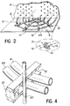
- the vibration bars 10 are now welded to each other by means of connecting pieces 20 called "pins".
- Figure 4 which shows their arrangement, represents several tubes 6 belonging to the same ply and whose tube disposed outside the bun is designated by 6th. It also represents the end of a pair of anti-vibration bars 10 from which the clips 11 have been removed.
- the pins 20 are welded at a distance from the outer tube 6e which is defined as a function of the expansion of the tubes 6 which will be carried out subsequently; it is, in practice, necessary to protect the tubes 6 with a thermally insulating cover during welding and which is then removed, and the stiffening action of the pins 20 is completed by straps 22 disposed between them and which oppose the deformation of the assembled half-bun under the action of its own weight.
- the straps 22 can be replaced by mechanical holding tools to oppose the deformation of the half-bun.
- the table 9 is dismantled and replaced by a frame 23 to which the straps 22 are attached and which supports the weight of the half-bun using the tie rods 15 which have been kept. We then arrive at the configuration shown in FIG. 5.
- the second half of the bun is then mounted by layers of tubes in the manner described above: installation of anti-vibration bars 10, checking of the clearances, possible replacement of the tubes 6 outside tolerances and installation of a new layer of tubes.
- the antivibration bars 10 of this second half are finally linked together by means of new pins 20.
- the tubes 6 are then correctly positioned and it is possible to expand them on the tube plate 13, after which the assembly of the steam generator is continued according to the prior art.
- the method of mounting tubes by plies which constitutes the invention, has the advantage of being able to control the faults of these tubes, including those which are located inside the bun and which were inaccessible with previous mounting methods.
- the risk of damage following an awkward introduction of the anti-vibration bars is completely eliminated.
- the tubes can be arranged with a much higher density, in particular in staggered, which was not possible with the previous mounting process.
Landscapes
- Engineering & Computer Science (AREA)
- Mechanical Engineering (AREA)
- Physics & Mathematics (AREA)
- Thermal Sciences (AREA)
- General Engineering & Computer Science (AREA)
- Monitoring And Testing Of Nuclear Reactors (AREA)
- Heat-Exchange Devices With Radiators And Conduit Assemblies (AREA)
- Automatic Assembly (AREA)
- Supports For Pipes And Cables (AREA)
- Load-Engaging Elements For Cranes (AREA)
- Motor Or Generator Cooling System (AREA)
Abstract
Procédé de montage de tubes (6) dans un générateur de vapeur.Method for mounting tubes (6) in a steam generator.
Il consiste essentiellement à introduire les tubes (6) par nappes horizontales (le générateur pouvant être couché dans ce but), à installer des barres antivibratoires (10) sur ces nappes, à disposer des poids sur ces barres (10) et à vérifier les jeux entre les tubes (6) et les barres (10) ; les tubes (6) hors tolérances peuvent être remplacés. On introduit ensuite la nappe de tubes immédiatement supérieure. L'ensemble du processus est répété jusqu'à ce que toutes les nappes soient montées.It essentially consists in introducing the tubes (6) by horizontal layers (the generator can be laid down for this purpose), in installing anti-vibration bars (10) on these layers, in placing weights on these bars (10) and in checking the clearances between the tubes (6) and the bars (10); the tubes (6) outside tolerances can be replaced. The next higher layer of tubes is then introduced. The whole process is repeated until all the layers are assembled.
Application aux générateurs de vapeur de centrales nucléaires. 
Description
La présente invention a pour objet un procédé de placement de tubes dans un générateur de vapeur.The present invention relates to a method of placing tubes in a steam generator.
Certains générateurs de vapeur, notamment ceux utilisés dans les centrales nucléaires, comportent trois mille tubes ou plus en forme de U dont les branches sont longues d'une dizaine de mètres. On enfile ces tubes dans une série de plaques entretoises percées, et leurs extrémités sont dudgeonnées dans une plaque tubulaire au contact de la boîte à eau primaire.Some steam generators, especially those used in nuclear power plants, have three thousand or more U-shaped tubes whose branches are ten meters long. These tubes are threaded into a series of pierced spacer plates, and their ends are expanded in a tubular plate in contact with the primary water box.
Les perçages permttent une disposition en nappes planes et parallèles des tubes, à l'intérieur desquelles ils sont placés concentriquement suivant l'écartement de leurs branches et le rayon de la partie courbe du U.The holes allow an arrangement in flat and parallel plies of the tubes, inside which they are placed concentrically according to the spacing of their branches and the radius of the curved part of the U.
Par ailleurs, la largeur des nappes diminue quand on s'éloigne de la nappe centrale, et comme les différentes nappes sont centrées sur le même plan, le contour général de la zone des parties courbes des U est celui d'une demi-sphère.In addition, the width of the layers decreases when one moves away from the central layer, and as the various layers are centered on the same plane, the general outline of the zone of the curved parts of the U is that of a hemisphere.
Les nappes étant très compactes, une analogie d'aspect a fait appeler cette zone "chignon".The tablecloths being very compact, an analogy of aspect made call this zone "bun".
Les problèmes qui se posent dans ce genre d'installations sont dus aux phénomènes vibratoires dont le générateur de vapeur est le siège : ce générateur est en effet de forme très allongée et sensible aux oscillations qui sont plus accentuées à son sommet où se trouve le chignon. L'impossibilité de disposer des plaques entretoises supplémentaires à cet endroit, jointe à la souplesse des tubes et à leurs longueurs libres différentes, engendre des comportements vibratoires complexes qu'il faut éliminer.The problems which arise in this kind of installations are due to the vibratory phenomena of which the steam generator is the seat: this generator is indeed of very elongated shape and sensitive to the oscillations which are more accentuated at its top where the bun is located . The impossibility of having additional spacer plates at this location, combined with the flexibility of the tubes and their different free lengths, generates complex vibrational behaviors which must be eliminated.
Pour cette raison, on insère des barres antivibratoires entre chaque nappe plane de tubes, dont on soude ensuite les extrémités débordant quelque peu du chignon à des "épingles" semi-circulaires disposées suivant des méridiens. On obtient ainsi un ensemble beaucoup plus rigide et d'un comportement vibratoire bien meilleur.For this reason, anti-vibration bars are inserted between each flat sheet of tubes, the ends of which projecting somewhat beyond the bun are then welded to semi-circular "pins" arranged along meridians. We obtain thus a much more rigid assembly and a much better vibratory behavior.
Toutefois, la mise en place de barres antivibratoires entre des nappes serrées, de plusieurs mètres de largeur, constituées de tubes plus ou moins déformés et dont ceux qui sont situés à l'intérieur du chignon sont presque inaccessibles, laisse subsister des problèmes : l'insertion est délicate même avec l'introduction préliminaire d'un fil de nylon entre les deux nappes de tubes concernées ; et surtout, les tubes excessivement gauchis sont presque toujours victimes d'éraflures, de chocs qui constituent autant d'amorces possibles de corrosion et qui sont d'autant plus susceptibles de se produire que le montage nécessite de coucher le générateur, et que les nappes inférieures sont alors fortement comprimées par le poids des autres nappes. Après le montage, les tubes sont inaccessibles et leurs défauts ne peuvent plus être rattrapés : on peut simplement essayer de prouver, à l'aide de sondes à long manche, que les jeux entre les barres antivibratoires et certains tubes ne sont pas trop importants. Ces mesures, effectuées dans de mauvaises conditions, sont trop imprécises et ne sont plus considérées comme fiables, et on essaye de développer des procédés à l'aide de courants de Foucault, qui ne permettront au mieux que de constater l'absence de malfaçons mais non d'y remédier.However, the installation of anti-vibration bars between tight sheets, several meters wide, made up of more or less deformed tubes and of which those located inside the bun are almost inaccessible, leaves problems: insertion is delicate even with the preliminary introduction of a nylon thread between the two plies of tubes concerned; and above all, excessively warped tubes are almost always victims of scratches, shocks which constitute as many possible primers of corrosion and which are all the more likely to occur as the assembly requires laying down the generator, and as the layers lower are then strongly compressed by the weight of the other layers. After assembly, the tubes are inaccessible and their faults can no longer be remedied: one can simply try to prove, using long-handled probes, that the clearances between the anti-vibration bars and certain tubes are not too great. These measurements, carried out in poor conditions, are too imprecise and are no longer considered to be reliable, and we are trying to develop processes using eddy currents, which will at best only make it possible to note the absence of defects but not to remedy it.
Cet état de fait entraîne pour conséquence une méfiance des organismes chargés d'examiner la sûreté des centrales nucléaires, ainsi que l'impossibilité de resserrer les nappes de tubes autant qu'on le voudrait.This state of affairs results in mistrust of the bodies responsible for examining the safety of nuclear power plants, as well as the impossibility of tightening the layers of tubes as much as one would like.
La présente invention concerne donc un nouveau procédé de placement de tubes dans un générateur de vapeur, dans lequel on vérifie l'absence de gauchissement de ces tubes en les montant nappe par nappe, ce qui permet de les ôter et de les remplacer s'ils sont hors tolérances.The present invention therefore relates to a new method of placing tubes in a steam generator, in which the absence of warping of these tubes is verified by mounting them layer by layer, which makes it possible to remove and replace them if they are out of tolerances.
Plus précisément, ce procédé concerne le placement de tubes par nappes planes, séparées par des barres intermédiaires, notamment antivibratoires, dans un générateur d e vapeur, caractérisé en ce qu'il comprend la répétition des opérations suivantes :
- mise en place d'une nappe de tubes,
- pose des barres intermédiaires au-dessus de cette nappe,
- chargement par des forces disposées le long des barres intermédiaires et perpendiculaires au plan de la nappe,
- vérification du jeu entre les barres intermédiaires et chacun des tubes de la nappe,
- enlèvement et remplacement des tubes dont le jeu est hors tolérances par des tubes corrects.More specifically, this method relates to the placement of tubes by flat layers, separated by intermediate bars, in particular antivibration bars, in a steam generator, characterized in that it includes the repetition of the following operations:
- installation of a sheet of tubes,
- laying of intermediate bars above this layer,
- loading by forces arranged along the intermediate bars and perpendicular to the plane of the sheet,
- verification of the clearance between the intermediate bars and each of the ply tubes,
- removal and replacement of tubes whose play is out of tolerance with correct tubes.
Selon un mode préféré de réalisation de l'invention, le générateur de vapeur est orienté, au moment du montage, de telle sorte que les nappes soient horizontales, et de plus les forces introduites simulent en importance et en répartition le poids des nappes à disposer au-dessus des nappes déjà mises en place.According to a preferred embodiment of the invention, the steam generator is oriented, during assembly, so that the sheets are horizontal, and moreover the forces introduced simulate in importance and in distribution the weight of the sheets to be disposed above the tablecloths already in place.
Ce procédé sera mieux compris à la lumière de la description qui suit d'exemples de réalisation donnés à titre explicatif et non limitatif. Cette description se réfère à des dessins annexés sur lesquels :
- - la figure 1 représente la coupe d'un générateur de vapeur connu utilisé dans l'industrie nucléaire,
- - la figure 2 représente l'opération de pose d'une nappe caractéristique du procédé de l'invention,
- - la figure 3 représente le générateur de vapeur après montage de la première moitié du chignon,
- - la figure 4 représente l'opération de soudage des épingles méridiennes du chignon,
- - la figure 5 représente le générateur de vapeur au début du montage de la seconde moitié du chignon.
- FIG. 1 represents the section of a known steam generator used in the nuclear industry,
- FIG. 2 represents the operation of laying a sheet characteristic of the method of the invention,
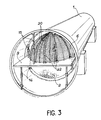
- FIG. 3 represents the steam generator after assembly of the first half of the bun,
- FIG. 4 represents the operation of welding the meridian pins of the bun,
- - Figure 5 shows the steam generator at the start of assembly of the second half of the bun.
La figure 1 représente donc un générateur de vapeur analogue à celui pour lequel le procédé objet de l'invention a été conçu. Au moment du montage des tubes, on a simplement assemblé la virole inférieure 1, les plaques entretoises 2 et la plaque tubulaire inférieure 3 ; la boîte à eau 4, ainsi que la virole supérieure 5 et tout l'appareillage situé à l'intérieur de celle-ci seront montés ultérieurement.FIG. 1 therefore represents a steam generator similar to that for which the process which is the subject of the invention has been designed. When mounting the tubes, we simply assembled the lower shell 1, the
Pour effectuer le montage des tubes 6, il faut tout d'abord coucher la virole inférieure 1 et l'orienter de telle façon que les nappes de tubes 6 puissent être montées horizontalement. On emploie pour ceci des échaufaudages munis de roulettes qui permettent sa rotation.To carry out the assembly of the
Comme illustré sur la figure 2, on commence par introduire une nappe de tube 6 située au centre du chignon. Les extrémités de chaque tube 6 ont été munies d'ogives coniques qui assurent le centrage des tubes 6 sur les trous des plaques entretoises 2. Les tubes sont livrés par le fabricant dans des caisses selon un ordre prédéterminé. Ces caisses ont une largeur d'environ 3 mètres. Il est donc très difficile sinon impossible pour les monteurs qui placent les tubes de saisir ceux qui sont disposés au plus près de l'axe de la caisse en se plaçant sur les côtés de celle-ci.As illustrated in Figure 2, we start by introducing a
Les caisses sont prévues avec un plancher intermédiaire entre chaque nappe de tubes. Les monteurs appréhendent les tubes à chaque extrémité des branches du "U" et seulement deux hommes sont nécessaires au montage des tubes dans un générateur de vapeur. La mise en place des tubes se faisant par l'extrémité des caisses, il n'y a pas de ce fait de limite aux dimensions des appareils à tuber.The boxes are provided with an intermediate floor between each layer of tubes. The fitters apprehend the tubes at each end of the branches of the "U" and only two men are required to mount the tubes in a steam generator. The establishment of the tubes being done by the end of the boxes, there is therefore no limit to the dimensions of the devices to be tubed.
Les monteurs enfoncent petit à petit les tubes 6 jusqu'à ce que les ogives débouchent sur la face extérieure de la plaque tubulaire 3. Elles sont alors enlevées et un léger dudgeonnage est apporté aux extrémités des tubes 6 de façon à les fixer axialement, sans toutefois que cet assemblage soit indémontable.The assemblers gradually insert the
On règle la hauteur d'une table 9 de façon à soutenir les tubes 6, dont le porte-à-faux est excessif compte tenu de leur souplesse. Quand la nappe tout entiére a été mise en place, on installe les barres antivibratoires 10 au-dessus de cette nappe après avoir vérifié qu'elles appartiennent sensiblement à un plan. De manière optimale, on dispose en éventail plusieurs barres 10 plus ou moins co udées de façon à entraver le débattement de tous les tubes 6 de la nappe, et ceci suivant des méridiens à peu près régulièrement répartis. Ces barres sont maintenues en place à l'aide d'agrafes 11 de plastique constituées de deux pinces déformables 12 et d'un corps de liaison 13 et fixées sur le tube extérieur 6e de la nappe : les pinces 12 enserrent ce tube 6e, et l'intervalle des pinces 12 permet le maintien des barres antivibratoires 10 avec un faible jeu.The height of a table 9 is adjusted so as to support the
On applique alors des forces sur les barres 10, dont la répartition et l'importance simulent le poids des nappes qui seront situées au-dessus de la nappe qui vient d'être posée. Ces forces ont été symbolisées sur la figure 2 par des flèches verticales descendantes ; elles peuvent être engendrées par tout dispositif approprié, tels que des vérins, ou plus simplement par des masses inertes.Forces are then applied to the
Les barres antivibratoires 10 pèsent donc avec une certaine répartition de forces sur les tubes 6 de la nappe ; elles sont en contact avec un certain nombre d'entre eux mais présentent un jeu vis-à-vis d'autres tubes 6 appartenant à cette nappe. C'est ce jeu qu'on évalue à l'aide d'un calibre quelconque car tous les tubes sont accessibles sans difficulté, ce qui n'était pas le cas avec le procédé antérieur.The
Les tubes 6 dont le jeu est trop important sont considérés comme faisant l'objet de malfaçons. Ils sont donc enlevés et remplacés par des tubes de rechange, ce que n'empêche pas le dudgeonnage léger auquel on a procédé auparavant pour maintenir en place ces tubes.The
Quand tous les tubes 6 de la nappe sont sains, on procède au montage de la nappe suivante, juste au-dessus des barres antivibratoires 10. On dispose au-dessus de cette deuxième nappe d'autres barres antivibratoires que l'on charge comme il a été expliqué plus haut ; bien entendu, les forces sont inférieures puisque les nappes dont il faut simuler le poids sont moins nombreuses. La vérification des jeux et la mise au rebut éventuelle de certains tubes de cette deuxième nappe se font suivant le même principe que précédemment, et on empile ainsi peu à peu les nappes de tubes.When all the
Quand la moitié du chignon a été constituée, la disposition d'ensemble du générateur de vapeur est indiquée figure 3. La table 9 qui avait permis, au début du montage, de soutenir la première nappe de tubes posée supporte maintenant le poids du demi-chignon. Elle doit donc être portée par des tirants 15 qui complètent l'action de supports 16 de la table 9 ; ces tirants 15 et supports 16 doivent être fixés à la virole inférieure 1 à leur autre extrémité comme on le verra plus loin.When half of the bun has been formed, the overall arrangement of the steam generator is shown in Figure 3. Table 9 which had allowed, at the start of assembly, to support the first layer of tubes laid now supports the weight of the half hair bun. It must therefore be carried by
Selon un mode de réalisation préféré de l'invention, on procède maintenant au soudage des barres antivibratoires 10 entre elles par l'intermédiaire de pièces de liaison 20 appelées "épingles". La figure 4, qui montre leur disposition, représente plusieurs tubes 6 appartenant à une même nappe et dont le tube disposé à l'extérieur du chignon est désigné par 6e. Elle repésente encore l'extrémité d'une paire de barres antivibratoires 10 dont les agrafes 11 ont été enlevées.According to a preferred embodiment of the invention, the
On dispose alors une cale de réglage 21 entre ces barres antivibratoires 10 de manière à maîtriser les déformations engendrées par le soudage de l'épingle 20 sur les extrémités des barres antivibratoires 10 ; on constate que les épingles 20 appartiennent à des plans orthogonaux à ceux des barres antivibratoires 10 et aux nappes de tubes 6, ce qui leur confère une disposition en méridiens sur le chignon, comme on le voit clairement sur la figure 3.There is then an
Les épingles 20 sont soudées à une distance du tube extérieur 6e qui est définie en fonction du dudgeonnage des tubes 6 qui sera effectué par la suite ; il est, dans la pratique, nécessaire de protéger les tubes 6 par une couverture thermiquement isolante au moment du soudage et que l'on retire ensuite, et on complète l'action de rigidification des épingles 20 par des sangles 22 disposées entre celles-ci et qui s'opposent à la déformation du demi-chignon assemblé sous l'action de son propre poids. Les sangles 22 peuvent être remplacées par des outillages de maintien mécaniques pour s'opposer à la déformation du demi-chignon.The
On assemble ensuite l'autre moitié du chignon.We then assemble the other half of the bun.
A partir de l'état du montage représenté figure 3, on procède d'abord à une rotation de 180° de la virole inférieure 1. Le demi-chignon assemblé passe donc en position basse ; il est nécessaire de tenir compte de son balourd par un système de freinage approprié.Starting from the state of the assembly shown in FIG. 3, first of all a 180 ° rotation of the lower ferrule 1. The assembled half-bun therefore moves to the low position; it is necessary to take account of its unbalance by an appropriate braking system.
Après l'achèvement de la rotation, la table 9 est démontée et remplacée par un cadre 23 auquel sont attachées les sangles 22 et qui soutient le poids du demi-chignon à l'aide des tirants 15 qui ont été conservés. On arrive alors à la configuration représentée figure 5.After the completion of the rotation, the table 9 is dismantled and replaced by a
La seconde moitié du chignon est alors montée par nappes de tubes de la façon décrite plus haut : mise en place de barres antivibratoires 10, vérification des jeux, remplacement éventuel des tubes 6 hors tolérances et mise en place d'une nouvelle nappe de tubes. les barres antivibratoires 10 de cette seconde moitié sont enfin liées entre elles au moyen de nouvelles épingles 20. Les tubes 6 sont alors correctement positionnés et il est possible de les dudgeonner sur la plaque tubulaire 13, après quoi le montage du générateur de vapeur est continué selon l'art antérieur.The second half of the bun is then mounted by layers of tubes in the manner described above: installation of
On constate donc que le procédé de montage des tubes par nappes, qui constitue l'invention, présente l'avantage de pouvoir maîtriser les malfaçons de ces tubes, y compris de ceux qui sont situés à l'intérieur du chignon et qui étaient inaccessibles avec les procédés de montage antérieurs. De plus, les risques de détériorations consécutives à une introduction maladroite des barres antivibratoires sont complètement éliminés.It can therefore be seen that the method of mounting tubes by plies, which constitutes the invention, has the advantage of being able to control the faults of these tubes, including those which are located inside the bun and which were inaccessible with previous mounting methods. In addition, the risk of damage following an awkward introduction of the anti-vibration bars is completely eliminated.
Il est donc possible de garantir une fabrication correcte aux autorités responsables de la sécurité des centrales nucléaires ; un autre avantage est que les tubes peuvent être disposés avec une densité beaucoup plus importante, notamment en quinconce, ce qui n'était pas possible avec le procédé de montage antérieur. It is therefore possible to guarantee correct manufacture to the authorities responsible for the safety of nuclear power plants; another advantage is that the tubes can be arranged with a much higher density, in particular in staggered, which was not possible with the previous mounting process.
Claims (5)
- mise en place d'une nappe de tubes (6),
- pose de barres intermédiaires (10) au-dessus de cette nappe,
- chargement par des forces disposées le long des barres intermédiaires (10) et perpendiculaires au plan de la nappe,
- vérification du jeu entre les barres intermédiaires (10) et chacun des tubes (6) de la nappe,
- enlèvement des tubes (6) dont le jeu avec les barres intermédiaires (10) est hors tolérances et remplacement par des tubes corrects.1. Method for placing tubes (6) by flat sheets separated by intermediate bars (10), in particular anti-vibration, in a steam generator, characterized in that it comprises repeating the following sequence of operations:
- installation of a sheet of tubes (6),
- laying of intermediate bars (10) above this sheet,
- loading by forces arranged along the intermediate bars (10) and perpendicular to the plane of the sheet,
- verification of the clearance between the intermediate bars (10) and each of the tubes (6) of the ply,
- removal of the tubes (6) whose play with the intermediate bars (10) is out of tolerance and replacement with correct tubes.
Applications Claiming Priority (2)
| Application Number | Priority Date | Filing Date | Title |
|---|---|---|---|
| FR8612126A FR2603364B1 (en) | 1986-08-27 | 1986-08-27 | METHOD FOR PLACING TUBES IN A STEAM GENERATOR |
| FR8612126 | 1986-08-27 |
Publications (2)
| Publication Number | Publication Date |
|---|---|
| EP0262011A1 true EP0262011A1 (en) | 1988-03-30 |
| EP0262011B1 EP0262011B1 (en) | 1991-05-15 |
Family
ID=9338532
Family Applications (1)
| Application Number | Title | Priority Date | Filing Date |
|---|---|---|---|
| EP87401930A Expired - Lifetime EP0262011B1 (en) | 1986-08-27 | 1987-08-25 | Method for placing tubes in a steam generator |
Country Status (10)
| Country | Link |
|---|---|
| US (1) | US4839951A (en) |
| EP (1) | EP0262011B1 (en) |
| JP (1) | JPH0723761B2 (en) |
| KR (1) | KR950007019B1 (en) |
| CN (1) | CN1007999B (en) |
| CA (1) | CA1274676A (en) |
| DE (2) | DE3770100D1 (en) |
| ES (1) | ES2002258B3 (en) |
| FR (1) | FR2603364B1 (en) |
| SU (1) | SU1706380A3 (en) |
Cited By (2)
| Publication number | Priority date | Publication date | Assignee | Title |
|---|---|---|---|---|
| FR2714626A1 (en) * | 1993-12-31 | 1995-07-07 | Framatome Sa | Removable supports for tubes of a heat exchanger during assembly and transport |
| FR2748795A1 (en) * | 1996-05-15 | 1997-11-21 | Framatome Sa | Tube bundle end support for heat exchanger |
Families Citing this family (18)
| Publication number | Priority date | Publication date | Assignee | Title |
|---|---|---|---|---|
| US5072786A (en) * | 1990-07-27 | 1991-12-17 | Electric Power Research Institute, Inc. | Anti-vibration support of U-bend flow tubes in a nuclear steam generator |
| FR2684172B1 (en) * | 1991-11-27 | 1993-12-31 | Framatome | HEAT EXCHANGER, WITH U-TUBES EQUIPPED WITH AN ANTI-THEFT SUPPORT DEVICE. |
| FR2709174B1 (en) * | 1993-08-20 | 1995-11-17 | Framatome Sa | Heat exchanger comprising means for holding anti-vibration bars inserted between the tubes of the heat exchanger bundle. |
| FR2713971B1 (en) * | 1993-12-21 | 1996-03-08 | Framatome Sa | Device for temporarily holding an end portion of a bundle of tubes of a heat exchanger. |
| JP4585414B2 (en) * | 2005-09-16 | 2010-11-24 | 三菱重工業株式会社 | Vibration preventing device and heat exchanger using the same |
| US8695688B2 (en) * | 2007-07-18 | 2014-04-15 | Babcock & Wilcox Canada Ltd. | Nubbed U-bend tube support |
| JP2012081475A (en) * | 2010-10-06 | 2012-04-26 | Mitsubishi Heavy Ind Ltd | Dissimilar material joint structure |
| JP5582004B2 (en) * | 2010-12-07 | 2014-09-03 | 株式会社Ihi | Fixing method of heat transfer tube runout prevention bar |
| JP5885949B2 (en) * | 2011-06-28 | 2016-03-16 | 三菱重工業株式会社 | Steam generator |
| JP5901266B2 (en) * | 2011-12-12 | 2016-04-06 | 三菱重工業株式会社 | Steam generator |
| CN103659169B (en) * | 2012-09-23 | 2016-06-22 | 丹阳市龙鑫合金有限公司 | A kind of method of the anti-vibration bar assembly preparing nuclear power generating sets |
| CN103317245B (en) * | 2013-06-05 | 2015-08-19 | 上海电气核电设备有限公司 | A kind of method of nuclear steam generator poling and anti-vibration strip welding equipment |
| US10619932B2 (en) | 2015-10-23 | 2020-04-14 | Hyfra Industriekuhlanlagen Gmbh | System for cooling a fluid with a microchannel evaporator |
| US11193715B2 (en) | 2015-10-23 | 2021-12-07 | Hyfra Industriekuhlanlagen Gmbh | Method and system for cooling a fluid with a microchannel evaporator |
| JP6898200B2 (en) * | 2017-10-05 | 2021-07-07 | 三菱パワー株式会社 | Heat exchanger |
| US11226139B2 (en) | 2019-04-09 | 2022-01-18 | Hyfra Industriekuhlanlagen Gmbh | Reversible flow evaporator system |
| CN111486740B (en) * | 2020-04-23 | 2021-09-28 | 中国原子能科学研究院 | Heat exchanger and method of assembling the same |
| CN112975268B (en) * | 2021-05-12 | 2021-08-06 | 上海电气核电设备有限公司 | Installation method of anti-seismic strip of steam generator |
Citations (2)
| Publication number | Priority date | Publication date | Assignee | Title |
|---|---|---|---|---|
| EP0011959A1 (en) * | 1978-11-30 | 1980-06-11 | Westinghouse Electric Corporation | Apparatus and method for installing rows of U-shaped tubes in a heat exchanger |
| FR2558933A1 (en) * | 1984-01-26 | 1985-08-02 | Westinghouse Electric Corp | STEAM GENERATOR FOR PRESSURE WATER REACTOR COMPRISING ANTI-VIBRATION BARS FOR STABILIZING HEAT TRANSFER TUBES |
Family Cites Families (7)
| Publication number | Priority date | Publication date | Assignee | Title |
|---|---|---|---|---|
| US3007679A (en) * | 1960-06-22 | 1961-11-07 | Westinghouse Electric Corp | Anti-vibration structure for heat exchanger tubes |
| US3212567A (en) * | 1962-05-08 | 1965-10-19 | Combustion Eng | Anti-vibration support means |
| US4173060A (en) * | 1977-06-24 | 1979-11-06 | Westinghouse Electric Corp. | System and method for retubing a steam generator |
| US4386456A (en) * | 1978-03-31 | 1983-06-07 | Phillips Petroleum Company | Method of assembling a unitary heat exchanger tube bundle assembly |
| JPS60245999A (en) * | 1984-05-21 | 1985-12-05 | Hokkaido Electric Power Co Inc:The | Heat exchanger |
| CA1255984A (en) * | 1984-11-13 | 1989-06-20 | Byre V. Gowda | Anti-vibration bars for nuclear steam generators |
| US4653576A (en) * | 1985-05-01 | 1987-03-31 | Westinghouse Electric Corp. | Expandable antivibration bar for a steam generator |
-
1986
- 1986-08-27 FR FR8612126A patent/FR2603364B1/en not_active Expired
-
1987
- 1987-08-25 DE DE8787401930T patent/DE3770100D1/en not_active Expired - Lifetime
- 1987-08-25 EP EP87401930A patent/EP0262011B1/en not_active Expired - Lifetime
- 1987-08-25 ES ES87401930T patent/ES2002258B3/en not_active Expired - Lifetime
- 1987-08-25 DE DE198787401930T patent/DE262011T1/en active Pending
- 1987-08-26 CN CN87105900A patent/CN1007999B/en not_active Expired
- 1987-08-26 CA CA000545427A patent/CA1274676A/en not_active Expired - Lifetime
- 1987-08-26 JP JP62212647A patent/JPH0723761B2/en not_active Expired - Lifetime
- 1987-08-26 SU SU874203235A patent/SU1706380A3/en active
- 1987-08-27 KR KR1019870009369A patent/KR950007019B1/en not_active Expired - Fee Related
- 1987-08-27 US US07/090,059 patent/US4839951A/en not_active Expired - Lifetime
Patent Citations (2)
| Publication number | Priority date | Publication date | Assignee | Title |
|---|---|---|---|---|
| EP0011959A1 (en) * | 1978-11-30 | 1980-06-11 | Westinghouse Electric Corporation | Apparatus and method for installing rows of U-shaped tubes in a heat exchanger |
| FR2558933A1 (en) * | 1984-01-26 | 1985-08-02 | Westinghouse Electric Corp | STEAM GENERATOR FOR PRESSURE WATER REACTOR COMPRISING ANTI-VIBRATION BARS FOR STABILIZING HEAT TRANSFER TUBES |
Non-Patent Citations (1)
| Title |
|---|
| PATENT ABSTRACTS OF JAPAN, vol. 10, no. 115 (M-474)[2172], 30 avril 1986; & JP-A-60 245 999 (HOTSUKAIDOU DENRIYOKU K.K.) 05-12-1985 * |
Cited By (2)
| Publication number | Priority date | Publication date | Assignee | Title |
|---|---|---|---|---|
| FR2714626A1 (en) * | 1993-12-31 | 1995-07-07 | Framatome Sa | Removable supports for tubes of a heat exchanger during assembly and transport |
| FR2748795A1 (en) * | 1996-05-15 | 1997-11-21 | Framatome Sa | Tube bundle end support for heat exchanger |
Also Published As
| Publication number | Publication date |
|---|---|
| JPH0723761B2 (en) | 1995-03-15 |
| KR950007019B1 (en) | 1995-06-26 |
| CN87105900A (en) | 1988-04-13 |
| CA1274676A (en) | 1990-10-02 |
| DE262011T1 (en) | 1988-09-01 |
| JPS6365202A (en) | 1988-03-23 |
| EP0262011B1 (en) | 1991-05-15 |
| FR2603364A1 (en) | 1988-03-04 |
| DE3770100D1 (en) | 1991-06-20 |
| FR2603364B1 (en) | 1988-11-10 |
| ES2002258B3 (en) | 1992-01-01 |
| US4839951A (en) | 1989-06-20 |
| ES2002258A4 (en) | 1988-08-01 |
| CN1007999B (en) | 1990-05-16 |
| SU1706380A3 (en) | 1992-01-15 |
| KR880003140A (en) | 1988-05-14 |
Similar Documents
| Publication | Publication Date | Title |
|---|---|---|
| EP0262011B1 (en) | Method for placing tubes in a steam generator | |
| FR2707382A1 (en) | Heat exchanger comprising a bundle of U-bent tubes and anti-vibration bars between the bent parts of the tubes. | |
| EP0731328A1 (en) | Heat exchanger with U-tubes, provided with a damping and anti- blowout device for securing tubes | |
| BE897648A (en) | Plates for welding gate bar nuclear fuel support | |
| CN212287365U (en) | Wind turbine blade fixture and wind turbine blade test system | |
| FR2618198A1 (en) | DEVICE FOR ANTIVIBRATORY SETTING OF COMPONENTS OF A SYSTEM AND IN PARTICULAR ANTIVIBRATORY SETTING BARS FOR TUBES OF A STEAM GENERATOR. | |
| EP0544579B1 (en) | U-tube heat exchanger with anti-blow-out supporting device | |
| EP0634607B1 (en) | Steam generator with removable cyclone separators | |
| EP0511908A1 (en) | Intervention process for working at power lines with a helicopter-carried worksbasket and fork | |
| EP0088363B1 (en) | Apparatus for suspending heat exchanger pipe bundles | |
| FR2532224A1 (en) | DEVICE, RETAINER, AND METHOD FOR ASSEMBLING NUCLEAR FUEL BAR SUPPORT GRIDS | |
| EP0145528A1 (en) | Storage rack for fuel elements of nuclear reactors | |
| WO2004064076A2 (en) | Method and device for loading a fuel assembly into the core of a nuclear reactor | |
| BE1006381A3 (en) | KEY ELEMENT AND USES THEREOF FOR INTEGRATION OR REMOVAL OF BARS AND FUEL REMOVAL OF A NUCLEAR FUEL Thurs. | |
| EP0626536B1 (en) | Steam generator equipped with a trapping device for foreign objects | |
| EP0294273B1 (en) | Metallic brackets | |
| FR2894085A1 (en) | Electrical cabinet for e.g. controller of airplane, has wiring support comprising crosspieces and posts on which bunched cables are assembled, and extending in plane parallel to face of furniture when it is fixed to face of furniture | |
| EP0104119B1 (en) | Process and installation for assembling frame members in grids | |
| BE897426A (en) | NUCLEAR FUEL ELEMENT, | |
| EP0574276B1 (en) | Suitcase for the storage and transport of electronic boards or other small material for electronic equipment | |
| FR2551850A1 (en) | PROCESS FOR CONSTRUCTING A ROTOR CYLINDRICAL ASSEMBLY FOR A ROTARY REGENERATIVE HEAT EXCHANGER | |
| EP0504039B1 (en) | Method and device to produce an annular workpiece of sheetmetal | |
| FR3107868A1 (en) | WIRED ELEMENT SUPPORT DEVICE, ADAPTABLE ACCORDING TO THE WHEELBASE OF A VEHICLE STRUCTURE | |
| EP3479383A1 (en) | Nuclear reactor, methods for assembling and replacing thermocouple ducts, assembly for implementing these methods | |
| FR2494602A1 (en) | Jig for assembling large electrodes in electrostatic dust extractors - esp. for cleaning large vol. of gas in metallurgical works, where jig prevents distortion of electrodes |
Legal Events
| Date | Code | Title | Description |
|---|---|---|---|
| PUAI | Public reference made under article 153(3) epc to a published international application that has entered the european phase |
Free format text: ORIGINAL CODE: 0009012 |
|
| AK | Designated contracting states |
Kind code of ref document: A1 Designated state(s): BE CH DE ES GB IT LI NL |
|
| ITCL | It: translation for ep claims filed |
Representative=s name: JACOBACCI CASETTA & PERANI S.P.A. |
|
| GBC | Gb: translation of claims filed (gb section 78(7)/1977) | ||
| TCNL | Nl: translation of patent claims filed | ||
| DET | De: translation of patent claims | ||
| 17P | Request for examination filed |
Effective date: 19880901 |
|
| 17Q | First examination report despatched |
Effective date: 19900219 |
|
| GRAA | (expected) grant |
Free format text: ORIGINAL CODE: 0009210 |
|
| AK | Designated contracting states |
Kind code of ref document: B1 Designated state(s): BE CH DE ES GB IT LI NL |
|
| REF | Corresponds to: |
Ref document number: 3770100 Country of ref document: DE Date of ref document: 19910620 |
|
| ITF | It: translation for a ep patent filed | ||
| GBT | Gb: translation of ep patent filed (gb section 77(6)(a)/1977) | ||
| REG | Reference to a national code |
Ref country code: ES Ref legal event code: FG2A Ref document number: 2002258 Country of ref document: ES Kind code of ref document: B3 |
|
| PLBE | No opposition filed within time limit |
Free format text: ORIGINAL CODE: 0009261 |
|
| STAA | Information on the status of an ep patent application or granted ep patent |
Free format text: STATUS: NO OPPOSITION FILED WITHIN TIME LIMIT |
|
| 26N | No opposition filed | ||
| PGFP | Annual fee paid to national office [announced via postgrant information from national office to epo] |
Ref country code: NL Payment date: 19960926 Year of fee payment: 10 |
|
| PG25 | Lapsed in a contracting state [announced via postgrant information from national office to epo] |
Ref country code: NL Free format text: LAPSE BECAUSE OF NON-PAYMENT OF DUE FEES Effective date: 19980301 |
|
| NLV4 | Nl: lapsed or anulled due to non-payment of the annual fee |
Effective date: 19980301 |
|
| PGFP | Annual fee paid to national office [announced via postgrant information from national office to epo] |
Ref country code: CH Payment date: 19990805 Year of fee payment: 13 |
|
| PGFP | Annual fee paid to national office [announced via postgrant information from national office to epo] |
Ref country code: ES Payment date: 19990817 Year of fee payment: 13 |
|
| PG25 | Lapsed in a contracting state [announced via postgrant information from national office to epo] |
Ref country code: ES Free format text: LAPSE BECAUSE OF NON-PAYMENT OF DUE FEES Effective date: 20000826 |
|
| PG25 | Lapsed in a contracting state [announced via postgrant information from national office to epo] |
Ref country code: CH Free format text: LAPSE BECAUSE OF NON-PAYMENT OF DUE FEES Effective date: 20000831 Ref country code: LI Free format text: LAPSE BECAUSE OF NON-PAYMENT OF DUE FEES Effective date: 20000831 |
|
| REG | Reference to a national code |
Ref country code: CH Ref legal event code: PL |
|
| REG | Reference to a national code |
Ref country code: GB Ref legal event code: IF02 |
|
| REG | Reference to a national code |
Ref country code: GB Ref legal event code: 732E |
|
| REG | Reference to a national code |
Ref country code: ES Ref legal event code: FD2A Effective date: 20010911 |
|
| PG25 | Lapsed in a contracting state [announced via postgrant information from national office to epo] |
Ref country code: IT Free format text: LAPSE BECAUSE OF NON-PAYMENT OF DUE FEES;WARNING: LAPSES OF ITALIAN PATENTS WITH EFFECTIVE DATE BEFORE 2007 MAY HAVE OCCURRED AT ANY TIME BEFORE 2007. THE CORRECT EFFECTIVE DATE MAY BE DIFFERENT FROM THE ONE RECORDED. Effective date: 20050825 |
|
| PGFP | Annual fee paid to national office [announced via postgrant information from national office to epo] |
Ref country code: GB Payment date: 20060825 Year of fee payment: 20 |
|
| PGFP | Annual fee paid to national office [announced via postgrant information from national office to epo] |
Ref country code: BE Payment date: 20060918 Year of fee payment: 20 |
|
| PGFP | Annual fee paid to national office [announced via postgrant information from national office to epo] |
Ref country code: DE Payment date: 20061002 Year of fee payment: 20 |
|
| REG | Reference to a national code |
Ref country code: GB Ref legal event code: PE20 |
|
| PG25 | Lapsed in a contracting state [announced via postgrant information from national office to epo] |
Ref country code: GB Free format text: LAPSE BECAUSE OF EXPIRATION OF PROTECTION Effective date: 20070824 |
|
| BE20 | Be: patent expired |
Owner name: *FRAMATOME ANP Effective date: 20070825 |