EP0731328A1 - Heat exchanger with U-tubes, provided with a damping and anti- blowout device for securing tubes - Google Patents
Heat exchanger with U-tubes, provided with a damping and anti- blowout device for securing tubes Download PDFInfo
- Publication number
- EP0731328A1 EP0731328A1 EP96400463A EP96400463A EP0731328A1 EP 0731328 A1 EP0731328 A1 EP 0731328A1 EP 96400463 A EP96400463 A EP 96400463A EP 96400463 A EP96400463 A EP 96400463A EP 0731328 A1 EP0731328 A1 EP 0731328A1
- Authority
- EP
- European Patent Office
- Prior art keywords
- tubes
- bundle
- heat exchanger
- bars
- exchanger according
- Prior art date
- Legal status (The legal status is an assumption and is not a legal conclusion. Google has not performed a legal analysis and makes no representation as to the accuracy of the status listed.)
- Granted
Links
Images


Classifications
-
- F—MECHANICAL ENGINEERING; LIGHTING; HEATING; WEAPONS; BLASTING
- F28—HEAT EXCHANGE IN GENERAL
- F28D—HEAT-EXCHANGE APPARATUS, NOT PROVIDED FOR IN ANOTHER SUBCLASS, IN WHICH THE HEAT-EXCHANGE MEDIA DO NOT COME INTO DIRECT CONTACT
- F28D7/00—Heat-exchange apparatus having stationary tubular conduit assemblies for both heat-exchange media, the media being in contact with different sides of a conduit wall
- F28D7/06—Heat-exchange apparatus having stationary tubular conduit assemblies for both heat-exchange media, the media being in contact with different sides of a conduit wall the conduits having a single U-bend
-
- F—MECHANICAL ENGINEERING; LIGHTING; HEATING; WEAPONS; BLASTING
- F28—HEAT EXCHANGE IN GENERAL
- F28D—HEAT-EXCHANGE APPARATUS, NOT PROVIDED FOR IN ANOTHER SUBCLASS, IN WHICH THE HEAT-EXCHANGE MEDIA DO NOT COME INTO DIRECT CONTACT
- F28D7/00—Heat-exchange apparatus having stationary tubular conduit assemblies for both heat-exchange media, the media being in contact with different sides of a conduit wall
-
- F—MECHANICAL ENGINEERING; LIGHTING; HEATING; WEAPONS; BLASTING
- F22—STEAM GENERATION
- F22B—METHODS OF STEAM GENERATION; STEAM BOILERS
- F22B37/00—Component parts or details of steam boilers
- F22B37/02—Component parts or details of steam boilers applicable to more than one kind or type of steam boiler
- F22B37/10—Water tubes; Accessories therefor
- F22B37/20—Supporting arrangements, e.g. for securing water-tube sets
- F22B37/205—Supporting and spacing arrangements for tubes of a tube bundle
- F22B37/206—Anti-vibration supports for the bends of U-tube steam generators
-
- F—MECHANICAL ENGINEERING; LIGHTING; HEATING; WEAPONS; BLASTING
- F28—HEAT EXCHANGE IN GENERAL
- F28F—DETAILS OF HEAT-EXCHANGE AND HEAT-TRANSFER APPARATUS, OF GENERAL APPLICATION
- F28F9/00—Casings; Header boxes; Auxiliary supports for elements; Auxiliary members within casings
- F28F9/007—Auxiliary supports for elements
- F28F9/013—Auxiliary supports for elements for tubes or tube-assemblies
- F28F9/0132—Auxiliary supports for elements for tubes or tube-assemblies formed by slats, tie-rods, articulated or expandable rods
Definitions
- the invention relates to a heat exchanger comprising a bundle of U-bent tubes and anti-vibration bars between the bent parts of the tubes.
- the invention applies in particular to a steam generator of a pressurized water nuclear reactor.
- the steam generators of pressurized water nuclear reactors comprise U-shaped bent tubes having two parallel straight branches crimped at their ends in a tubular plate.
- the tubes of the bundle are thus maintained in a regular arrangement in which the straight branches are all parallel to each other and the tubes arranged in flat sheets parallel to each other in each of which the curved parts of the tubes have decreasing radii of curvature from the outside towards the inside of the sheet.
- the curved parts of the tubes of each of the layers of the bundle have different radii of curvature and are juxtaposed so as to constitute a structure of substantially hemispherical shape called a bun, at the top of the bundle of the steam generator.
- pressurized water at high temperature circulates in the bundle tubes and drinking water is brought into contact with the external exchange surface of the tubes along which it moves in the vertical direction by heating and then vaporizing, to come out as vapor at the top of the steam generator.
- the circulation of fluids in contact with the tubes can cause vibrations which are likely to cause damage to the tubes if they are not maintained effectively.
- the right part of the tubes is engaged in spacers located at regular distances from each other according to the height of the beam. These straight parts are therefore effectively maintained by rigid elements.
- the curved parts of the tubes of the bundle constituting the bun must also be maintained and generally used for this purpose anti-vibration bars which are interposed each between two plies of adjacent tubes of the bundle and arranged in substantially radial directions of the bun. These anti-vibration bars as described for example in patent US-A-3,007,679 are generally connected two by two of their ends inside the bun and placed angularly to form V-shaped structures.
- the outer ends of the antivibration bars opposite their central part project from the tubes constituting the outer layer of the bun and are interconnected by connecting means ensuring the maintenance of the antivibration bars.
- a wedging device comprising connecting means between the outer ends of anti-vibration bars arranged in sets of at least two bars in which the bars are aligned and have aligned through openings, one of which is tapped.
- the connecting means of the anti-vibration bars comprise a pin which is inserted into the aligned openings of the set of anti-vibration bars and into the bore of spacers which are each inserted between two successive anti-vibration bars.
- the spindle which has a threaded end is screwed into the tapped opening of an anti-vibration bar located at the end of the row.
- the spindle is also secured to a rotation blocking element which can be welded to a spacer.
- a rotation blocking element which can be welded to a spacer.
- an anti-vibration wedging device comprising connecting means between the outer ends of the anti-vibration bars arranged in sets of at least two bars in which the bars are aligned and comprise aligned through openings.
- the connecting means between the ends of the anti-vibration bars include a screw whose head is intended to come to bear on a first anti-vibration bar and whose threaded rod is screwed into a spacer.
- the spacer is fixed either in a second spacer, or in a threaded fixing element, by a threaded part. The threaded parts of the screw and the spacer pass through the anti-vibration bars through aligned openings.
- All anti-vibration wedging devices comprising anti-vibration bars require an anti-take-off device to keep them inside the bun.
- Anti-theft stirrups are also used in patents FR 2 644 281, FR-A-2 664 965 and FR 93 / 12.514, their fixing being ensured by mechanical means in order to avoid welding.
- the anti-take-off stirrups have the drawback of maintaining the anti-vibration device, by making the retaining force bear on certain tubes of the bundle, the tubes being a sensitive element in the operation of the steam generator, we therefore sought to carry out the restraint effort from elements other than the tubes
- FR-A-91-14655 filed by the company FRAMATOME means of fixing the anti-vibration bars have been proposed to prevent their ejection outside the bundle in the steam generator in service, which comprise an elongated structure fixed on the spacer plate of the steam generator closest to the curved parts of the tubes constituting the bun.
- the elongated structure generally constituted in the form of a rail is fixed on the upper face of the spacer plate, in a direction perpendicular to the plies of tubes, inside the central free space constituting the water street of the generator. steam.
- the elongated fixing structure comprises, at each of the spaces between two pairs of plies of adjacent tubes, at least one notch in which the internal part of the anti-vibration bar can be engaged.
- This anti-theft device while eliminating the aforementioned drawback of making the effort bear retained on the tubes, requires during assembly operations a fairly long installation, taking into account the positioning of the anti-vibration bars in a large number of notches and does not ensure complete support in position of the anti-vibration device.
- the object of the invention is therefore to propose a heat exchanger comprising a bundle of U-bent tubes so as to have two straight branches and a curved part between the two straight branches, the bundle tubes being located in a regular arrangement in which the straight branches are all parallel to each other and the tubes arranged in planar plies parallel to each other, a bundle envelope surrounding the bundle of tubes, a plurality of anti-vibration bars interposed between the adjacent plies of the tubes in their curved part, to present an end outside the bundle, connecting means between the outer end parts of the anti-vibration bars and an anti-take-off device which does not bring the retaining force onto the bundle tubes, which is d '' simpler mounting than known devices and which ensures complete retention of the anti-vibration bars ires and their means of connection.
- all of said connecting means is connected to at least one support integral with the bundle envelope so as to constitute the anti-theft device of the anti-vibration bars allowing limited movement of the set of anti-vibration bars and of their connecting means in a direction parallel to the straight branches of the tubes.
- Another object of the invention is to provide a heat exchanger comprising a bundle of U-bent tubes so as to have two branches straight and a curved part between the two straight branches, the tubes of the bundle being located in a regular arrangement in which the straight branches are all parallel to each other and the tubes arranged in flat sheets parallel to each other, a bundle envelope surrounding the bundle of tubes, a plurality of anti-vibration bars inserted between the adjacent plies of the tubes in their curved part, so as to present an end outside the bundle and connecting means between the external end parts of the anti-vibration bars in a plurality sets of at least two bars in which the bars are aligned, designed to limit the number of connecting pieces and to facilitate assembly.
- Figure 1 is an elevational view in partial section through a vertical plane of a steam generator of a pressurized water nuclear reactor.
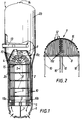
- FIG. 2 is a schematic sectional view of the upper part of the bun in a plane perpendicular to that of FIG. 1.
- FIG. 3A is a detailed sectional view of FIG. 1 showing the ends of the anti-vibration bars on a part of the bun with a schematic representation of the connection means in the case of a steam generator having an array of square pitch tubes.
- FIG. 3B is a view similar to the view in FIG. 3A, in the case of a steam generator having a bundle of tubes with triangular pitch.
- Figure 4 is a perspective view of a portion of the tube support device according to the invention showing the connecting means and the anti-flight device.
- FIG. 4A is a detailed view of a support pad for the connection means on a tube.
- Figure 5 is a perspective view of a detail of the tube support device.
- Figure 5A is a sectional view of a detail of the central comb.
- Figure 6 is a sectional view showing the anti-theft device.
- FIG. 1 we see a steam generator of a pressurized water nuclear reactor generally designated by the reference 1.
- the steam generator comprises an outer casing 2 representing a lower part 2a having the shape of a cylindrical shell in which the bundle of tubes 3 of the steam generator is disposed, inside a bundle casing 4.
- the part upper 2b of the envelope 2 of the steam generator 1 has a diameter greater than the diameter of the lower part 2a and contains means for separating and drying the steam produced in contact with the bundle 3.
- the lower end portion of the shell 2a of the casing 2 is integral with a tubular plate 5 of very thick which is crossed by openings in which the bundle tubes 3 are introduced and fixed by welding and crimping (mechanical or hydraulic for example).
- a hemispherical casing 6 delimiting the water box of the steam generator in two parts separated by a partition 7.
- Each of the two parts of the water box is connected by a tube to the primary circuit of the nuclear reactor in which the water circulates under cooling pressure of the reactor core.
- the bundle 3 consists of tubes 10 which are bent and have a U-shape.
- Each of the tubes 10 comprises two rectilinear branches 10a, 10b and a substantially semi-circular curved part 10c between the straight branches 10a and 10b.
- the ends of the branches 10a and 10b are engaged and crimped in openings passing through the tubular plate 5, on either side of the partition 7.
- the straight branches 10a, 10b of the tubes 10 of the bundle are also engaged in openings passing through spacer plates 8 arranged spaced apart according to the height of the bundle.
- the network of openings of each of the spacer plates reproduces the network of openings of the tubular plate 5, so that the branches 10a and 10b are maintained in parallel arrangements.
- the network of openings of the tubular plate 5 and of the spacer plates 8 comprises rectilinear rows in which the straight branches of tubes 10 are engaged, the curved part 10c of which has a decreasing radius of curvature from the outside towards the inside the beam.
- the bundle tubes thus constitute successive layers 12 which are visible in particular in FIG. 2.
- the radii of curvature of the curved parts 10c or tube hangers are decreasing from the outside to the inside, that is to say from top to bottom; in addition, the radius of curvature of the outer tube of the sheet having the maximum radius of curvature decreases from the inner central part towards the outside of the bundle.
- the bun 9 constituted by the hangers 10c juxtaposed with the tubes 10 has a substantially hemispherical shape.
- the networks of engagement openings of the tubes of the tube plate 5 and of the spacer plates 8 are interrupted at the central part of the plates in a diametrical direction, so as to delimit a free space or street of water 11 at the central part of the beam between the branches of the tubes having the smallest radii of curvature under the small hangers which are aligned in the diametrical direction of the water street 11.
- the steam generator 1 comprises a torus 13 disposed above the upper part of the bundle envelope 4 in which the bun 9 is placed.
- pressurized water for cooling the reactor enters one of the compartments of the water box so as to be distributed inside the branches 10a of the tubes 10 of the bundle opening into this entry compartment.
- the pressurized water circulates inside the tubes to exit into the second compartment of the water box through the second branches 10b of the tubes 10.
- the water recovered at the outlet of the tubes of the bundle is returned to the reactor vessel nuclear via a primary circuit pipe.
- the feed water introduced into the envelope of the steam generator 2 through the feed toroid 13 circulates from top to bottom in an annular space formed between the bundle envelope 4 and the outer casing 2 of the steam generator then enters the inside of the bundle casing 4 to come into contact with the tubes 10 above the upper face of the tube plate 5.
- the supply water circulates from bottom to top inside the bundle, in contact with the tubes and heats up then vaporizes by heat exchange with pressurized water circulating inside the tubes.
- the vapor formed in contact with the bundle tubes is sent to the upper part 2b of the steam generator to be dried and then discharged through the upper end 14 of the steam generator.
- the bundle tubes inside each of the flat plies of tubes 12 are placed so as to have a certain spacing and the plies are also arranged with respect to each other, with a certain spacing.
- the steam generator feed water can thus circulate in contact with the entire external surface of the tubes.
- the outer ends 15b of the branches of the anti-vibration bars project from the upper surface of the bun and allow the fixing of the anti-vibration bars.
- an anti-vibration bar will designate any branch of a V-shaped assembly 15.
- FIGS 3A and 3B there is shown in a sectional view of the plies of tubes in their upper part, part of a wedging assembly according to the invention, in the case of a bundle of tubes held in an arrangement with square mesh network and in the case of a bundle of tubes held in a triangular mesh network arrangement, respectively.
- the bundle tubes are held in a regular network arrangement by the openings of the tube plate 5 and by the through openings of the spacer plates 8 which comprise networks of similar openings.
- the arrangement of the tubes in the case of a triangular mesh network results in particular in a smaller space between the successive layers of tubes than in the case of a square mesh network.
- the device according to the invention applies as well in the case of a network of tight tubes with triangular meshes as in the case of a network with square meshes.
- FIGS. 3A and 3B show the tubes 10 or 10 ′ of the network of tubes constituting the external layers of the bun of the steam generator.
- the tubes 10 or 10 ′ constitute successive parallel plies between which the anti-vibration bars 15 or 15 ′ are interposed.
- the layers of tubes are formed by the upper bent portions of the juxtaposed tubes and with decreasing radii from the outside towards the inside of the bun.
- the anti-vibration bars 15 have ends 15b projecting outside the bun and arranged in alignment with one another to form alignments of variable length.
- the projecting ends 15b of the antivibration bars are connected together by connecting means 20 making it possible to ensure the connection of two or a greater number of antivibration bars constituting a set of aligned bars.
- connection means 20 ′ making it possible to link together the ends of a set of two or more anti-vibration bars.
- connection means 20 of a wedging device making it possible to connect the ends of the anti-vibration bars 15 to one another.
- Each of the connecting means 20 consists of an elongated piece 21 called a comb and comprising notches 21a, of a closing bar constituting the cover 22 intended to be positioned on the notches 21a, and means for fixing the cover to the comb constituted by one or more screws 23.
- the notches 21a are dimensioned so as to receive the ends of the anti-vibration bars 15.
- a comb 21 has at least two notches to allow the connection of the anti-vibration bars.
- the central comb which turns out to be the most important can comprise for example, up to thirty notches.
- preferential anti-vibration bars 15 are used which have notches in their end part.
- the notches of the antivibration bars 15 are positioned facing the notch of the comb so as to come to fit on the bottom of the notch of the comb, which ensures the effective maintenance of the end of the antivibration bar on the means of connection 20.
- the depth and the width of the notches of the comb are dimensioned so that the section of the anti-vibration bar 15 situated in the notch 21a of the comb comes approximately to fill said notch.
- the comb 21 has one or more tapped holes arranged between the notches on the face where the openings of the notches are located and intended to receive the connecting screws 23.
- the cover 22 has the form of an elongated bar and has one or more holes for the passage of the connecting screws 23.
- certain combs have complementary tapped holes arranged in the face where the openings of the notches are located and also in the end face of said combs, as will be explained below.
- stops 24 composed of a shoe 25, a jumper 26 and d 'A screw 27, are installed on the combs and come to bear on certain tubes 10 located towards the outside of the bun 9.
- the detailed drawing of the stop 24 is shown in Figure 4A.
- the shoe 25 has the shape of a small elongated plate, it has a rounded profile 25a recessed the size of the outside profile of a tube 10, this rounded profile represents the bearing surface on the tube; the width of said stop is slightly greater than the diameter of a tube except on a part where the stop has two recesses 25b; said abutment has an oblong hole between the two recesses, arranged lengthwise to allow adjustment of the position of the abutment during assembly.
- the rider 26 has a section in the shape of an inverted U, its length is substantially that of the recesses of the shoe 25, it is equipped with an oblong hole and is positioned on the shoe 25, at the level of the recesses.
- the screw 27 secures the shoe 25 and the rider 26 on the comb 21 by screwing into a threaded hole existing on the comb.
- a weld between the rider 26 and the comb 21 ensures the final positioning of the shoe 25.
- a weld point between the screw head 27 and the rider 26 ensures the inessibility of the screw 27.
- the connecting means 20 connecting the ends of the anti-vibration bars 15 located in the same meridian plane of the bun are all integral with one another by the fact that two successive connecting means 20 trap one end 15 b of the common anti-vibration bar 15 which is therefore located inserted into two successive combs 21.
- anti-vibration bars 15 connected to two successive connecting means then have two notches to be inserted into the notches of the two successive combs.
- arches 30 are arranged arranged in parallels of the hemispherical shape of the bun, arranged outside of the bun 9 and connecting together the various end connection assemblies .
- connection between the hoops 30 and the connecting means 20 is achieved by the fact that each hoop is connected to a comb 21 of each assembly for connecting the ends.
- the connection between a hoop 30 and a comb 21 is carried out by a screw 31 passing through the hoop 30 in which a hole has been arranged and which is screwed into the tapped hole located in the end face of the comb 21 and described above.
- arches 30 there will be seven arches 30 to hold all the ends of the anti-vibration bars in a rigid assembly.
- the different arches 30 have different radii depending on their location above the bun.
- the positioning of the bundle tubes and the anti-vibration bars can be carried out according to the method described in patent FR-A-2 603 364 from the company FRAMATOME.
- the tubes are mounted in successive layers from the largest layer located in the center according to the plane of FIG. 1 towards the layers of decreasing size and progressively inserting the anti-vibration bars, when half of the beam is mounted, the steam generator is rotated 180 ° along its axis then located in a horizontal position and the other half of the bundle is mounted, starting from the largest dimension of the layer towards the decreasing sizes of layers.
- central arch 30 In order to be able to install the central arch 30 and the central comb 21, there is a central comb composed of two half-combs, the longitudinal assembly of which is carried out by a dovetail type assembly as shown in FIG. 5A .
- Each half-comb is equipped with a support console 28 which is screwed with the cover 22 of the comb.
- the support brackets 28 are mounted with the covers of each half-comb and have a tapped hole to receive a fixing screw.
- the hoop is fitted with lugs 29 which are fixed by means of a fixing screw, passing through the lug and being screwed into the tapped hole of the support brackets 28.
- the assembly of the anti-vibration wedging device constituted by the anti-vibration bars 15, the end connection assemblies and the arches 30, is held by an anti-flight device.
- the previously described wedging device can move as a whole between the plies of tubes.
- the initial positioning of the device produced during assembly could be modified in particular during the operation of the steam generator.
- devices with anti-flight stirrups retained by the tubes or with a rail on the spacer plate located near the bun were used.
- supports 40 are used which are fixed to the bundle casing 4 and connected to the anti-vibration wedging device.
- the anti-take-off device which we will describe could be used with an anti-vibration wedging device different from that described above and in particular at the level of the connections of the ends of the anti-vibration bars.
- the support 40 intended to ensure the anti-takeoff function consists of a metal tab 41 rigidly fixed, by welding on the bundle envelope 4.
- the support tab 41 has at its end opposite to the bundle envelope 4, a hinge 42 intended to receive a dowel 44.
- the dowel 44 is arranged in a direction parallel to the axis of the steam generator.
- a lug 32 rigidly fixed by welding and integral with the arch.
- the tab 32 is substantially flat and disposed in a substantially horizontal position, below the hinge 42 and the support tab 41, which are located in the extension of one another with their lower faces located in the same horizontal plane 43.
- the tab 32 has an opening 33 of dimensions slightly larger than that of the section of the plug 44.
- the pin 44 longer than the length of the hinge 42 is introduced into the hinge 42 so as to protrude a few millimeters above the hinge 42, and several centimeters below the hinge 42 by crossing the opening of the tab 32. It is then welded, in the upper part, by a weld 45 on the upper face of the hinge 42 .
- the device thus constituted with the supports makes it possible to ensure that the whole of the anti-vibration wedging device will be well maintained in a position close to that established during assembly, and limits both the vertical movement of the anti-vibration device upwards. steam generator and its tilting.
- the opening 33 in the tab 32 is larger than the pin 44 and therefore allows limited movement of the support device in a horizontal plane.
- a washer 46 is positioned at the lower end of the dowel 44 and fixed to said dowel by a weld 47, this makes it possible to ensure that the tab 32 of the hoop 30 can in no way case come out of its threaded position on the ankle 44.
- the support device thus described is reproduced at the two ends of the arch 30.
- the device for fixing the ends of the anti-vibration bars could be produced according to a device already known and be associated with anti-theft supports such as that which has been described.
- the anti-take-off device could be produced in a different way, on the condition of allowing the production of a limited clearance for the movement of all of the connecting means.
- the anti-vibration bars may be of a different shape from that which has been described.
- the invention applies in the case of any steam generator or heat exchanger comprising a regular network of tubes comprising curved parts between which are inserted anti-vibration bars.
Abstract
Description
L'invention concerne un échangeur de chaleur comportant un faisceau de tubes cintrés en U et des barres antivibratoires entre les parties cintrées des tubes. L'invention s'applique notamment à un générateur de vapeur d'un réacteur nucléaire à eau sous pression.The invention relates to a heat exchanger comprising a bundle of U-bent tubes and anti-vibration bars between the bent parts of the tubes. The invention applies in particular to a steam generator of a pressurized water nuclear reactor.
Les générateurs de vapeur des réacteurs nucléaires à eau sous pression comportent des tubes cintrés en U présentant deux branches droites parallèles serties à leurs extrémités dans une plaque tubulaire.The steam generators of pressurized water nuclear reactors comprise U-shaped bent tubes having two parallel straight branches crimped at their ends in a tubular plate.
Les extrémités des tubes étant engagées dans des ouvertures traversant la plaque tubulaire, régulièrement réparties selon une répartition rectangulaire ou triangulaire, les tubes du faisceau sont ainsi maintenus dans une disposition régulière dans laquelle les branches droites sont toutes parallèles entre elles et les tubes disposés suivant des nappes planes parallèles entre elles dans chacune desquelles les parties cintrées des tubes présentent des rayons de courbure décroissants de l'extérieur vers l'intérieur de la nappe.The ends of the tubes being engaged in openings crossing the tube plate, regularly distributed in a rectangular or triangular distribution, the tubes of the bundle are thus maintained in a regular arrangement in which the straight branches are all parallel to each other and the tubes arranged in flat sheets parallel to each other in each of which the curved parts of the tubes have decreasing radii of curvature from the outside towards the inside of the sheet.
Les parties courbes des tubes de chacune des nappes du faisceau présentent des rayons de courbure différents et sont juxtaposés de manière à constituer une structure de forme sensiblement hémisphérique appelée chignon, à la partie supérieure du faisceau du générateur de vapeur.The curved parts of the tubes of each of the layers of the bundle have different radii of curvature and are juxtaposed so as to constitute a structure of substantially hemispherical shape called a bun, at the top of the bundle of the steam generator.
Pendant le fonctionnement du générateur de vapeur, de l'eau sous pression à haute température circule dans les tubes du faisceau et de l'eau alimentaire est amenée au contact de la surface extérieure d'échange des tubes le long desquels elle se déplace dans la direction verticale en s'échauffant puis en se vaporisant, pour ressortir sous forme de vapeur à la partie supérieure du générateur de vapeur.During operation of the steam generator, pressurized water at high temperature circulates in the bundle tubes and drinking water is brought into contact with the external exchange surface of the tubes along which it moves in the vertical direction by heating and then vaporizing, to come out as vapor at the top of the steam generator.
La circulation des fluides au contact des tubes peut provoquer des vibrations qui sont susceptibles d'entraîner des détériorations des tubes si ceux-ci ne sont pas maintenus de manière efficace.The circulation of fluids in contact with the tubes can cause vibrations which are likely to cause damage to the tubes if they are not maintained effectively.
La partie droite des tubes est engagée dans des entretoises situées à des distances régulières les unes des autres suivant la hauteur du faisceau. Ces parties droites sont donc maintenues de manière efficace par des éléments rigides. Les parties courbes des tubes du faisceau constituant le chignon doivent également être maintenues et l'on utilise généralement pour cela des barres antivibratoires qui sont intercalées chacune entre deux nappes de tubes adjacentes du faisceau et disposées suivant des directions sensiblement radiales du chignon. Ces barres antivibratoires comme décrites par exemple dans le brevet US-A-3.007.679 sont généralement reliées deux à deux de leurs extrémités à l'intérieur du chignon et placées de manière angulaire pour constituer des structures en forme de V.The right part of the tubes is engaged in spacers located at regular distances from each other according to the height of the beam. These straight parts are therefore effectively maintained by rigid elements. The curved parts of the tubes of the bundle constituting the bun must also be maintained and generally used for this purpose anti-vibration bars which are interposed each between two plies of adjacent tubes of the bundle and arranged in substantially radial directions of the bun. These anti-vibration bars as described for example in patent US-A-3,007,679 are generally connected two by two of their ends inside the bun and placed angularly to form V-shaped structures.
Les extrémités extérieures des barres antivibratoires opposées à leur partie centrale sont saillantes par rapport aux tubes constituant la couche externe du chignon et sont reliées entre elles par des moyens de liaison assurant le maintien des barres antivibratoires.The outer ends of the antivibration bars opposite their central part project from the tubes constituting the outer layer of the bun and are interconnected by connecting means ensuring the maintenance of the antivibration bars.
On a proposé divers moyens de liaison des extrémités extérieures des barres antivibratoires utilisant des éléments de fixation placés au-dessus de la surface supérieure du chignon.Various means of connecting the outer ends of the antivibration bars have been proposed using fastening elements placed above the upper surface of the bun.
On a d'abord proposé comme par exemple dans le brevet US-A-3.007.679 de souder les extrémités des barres antivibratoires sur des éléments courbes appelés épingles disposés suivant des plans méridiens du chignon.It was first proposed as for example in US-A-3,007,679 to weld the ends of the anti-vibration bars on curved elements called pins arranged in meridian planes of the bun.
La fixation des barres antivibratoires mettant en oeuvre des soudures qui doivent être effectuées au voisinage des tubes du faisceau crée un risque de détériorations au niveau des tubes.The fixing of the antivibration bars implementing welds which must be carried out in the vicinity of the tubes of the bundle creates a risk of deterioration at the level of the tubes.
On a donc proposé des dispositifs de liaison mécanique permettant de relier les extrémités extérieures des barres antivibratoires à des pièces de fixation telles que des anneaux de retenue disposées au dessus de la surface extérieure du chignon.Mechanical connection devices have therefore been proposed making it possible to connect the outer ends of the anti-vibration bars to fastening parts such as retaining rings arranged above the outer surface of the bun.
Dans le brevet FR 2 644 281 déposé par FRAMATOME, on a prévu d'installer des arceaux de forme sensiblement semi-circulaire sur lesquels sont fixées des potences perpendiculaires aux arceaux et disposées en face de chaque extrémité de barre antivibratoire. Un système mécanique permet de relier les extrémités de chaque barre antivibratoire à la potence correspondante.In
On a également proposé des dispositifs de liaison mécanique permettant de relier les extrémités extérieures des barres antivibratoires par des liaisons mécaniques disposées de manière à regrouper des ensembles successifs d'extrémités de barres antivibratoires.Mechanical connection devices have also been proposed making it possible to connect the outer ends of the antivibration bars by mechanical connections arranged so as to group successive sets of ends of antivibration bars.
Dans le FR-A-2.664.965, déposé par FRAMATOME, on a proposé un dispositif de calage comportant des moyens de liaison entre les extrémités extérieures de barres antivibratoires disposées suivant des ensembles d'au moins deux barres dans lesquels les barres sont alignées et comportent des ouvertures traversantes alignées dont l'une est taraudée. Les moyens de liaison des barres antivibratoires comportent une broche qui est introduite dans les ouvertures alignées de l'ensemble de barres antivibratoires et dans l'alésage d'entretoises qui sont intercalées chacune entre deux barres antivibratoires successives. La broche qui comporte une extrémité filetée est vissée dans l'ouverture taraudée d'une barre antivibratoire située à l'extrémité de la rangée. La broche est également solidaire d'un élément de blocage en rotation qui peut être soudée sur une entretoise. Un tel dispositif présente des avantages par rapport aux dispositifs mécaniques connus antérieurement mais nécessite l'utilisation de broches dont la longueur est adaptée au nombre de barres et à la longueur de la rangée de barres antivibratoires dont les extrémités sont assemblées entre elles. Dans certains cas, il est nécessaire d'utiliser une broche de grande longueur, ce qui peut présenter des inconvénients en ce qui concerne les conditions de pose et la résistance mécanique de la broche.In FR-A-2,664,965, filed by FRAMATOME, a wedging device has been proposed comprising connecting means between the outer ends of anti-vibration bars arranged in sets of at least two bars in which the bars are aligned and have aligned through openings, one of which is tapped. The connecting means of the anti-vibration bars comprise a pin which is inserted into the aligned openings of the set of anti-vibration bars and into the bore of spacers which are each inserted between two successive anti-vibration bars. The spindle which has a threaded end is screwed into the tapped opening of an anti-vibration bar located at the end of the row. The spindle is also secured to a rotation blocking element which can be welded to a spacer. Such a device has advantages over previously known mechanical devices but requires the use of pins whose length is adapted to the number of bars and to the length of the row of anti-vibration bars, the ends of which are assembled together. In some cases, it is necessary to use a very long spindle, which can have drawbacks with regard to the installation conditions and the mechanical strength of the spindle.
Dans le brevet FR 93/12.514, déposé par FRAMATOME, on a proposé un dispositif de calage antivibratoire comportant des moyens de liaison entre les extrémités extérieures des barres antivibratoires disposés suivant des ensembles d'au moins deux barres dans lesquels les barres sont alignées et comportent des ouvertures traversantes alignées. Les moyens de liaison entre les extrémités des barres antivibratoires comportent une vis dont la tête est destinée à venir en appui sur une première barre antivibratoire et dont la tige filetée est vissée dans une entretoise. L'entretoise est fixée soit dans une seconde entretoise, soit dans un élément de fixation taraudé, par une partie filetée. Les parties filetées de la vis et de l'entretoise traversent les barres antivibratoires au travers des ouvertures alignées.In patent FR 93 / 12.514, filed by FRAMATOME, an anti-vibration wedging device has been proposed comprising connecting means between the outer ends of the anti-vibration bars arranged in sets of at least two bars in which the bars are aligned and comprise aligned through openings. The connecting means between the ends of the anti-vibration bars include a screw whose head is intended to come to bear on a first anti-vibration bar and whose threaded rod is screwed into a spacer. The spacer is fixed either in a second spacer, or in a threaded fixing element, by a threaded part. The threaded parts of the screw and the spacer pass through the anti-vibration bars through aligned openings.
L'inconvénient de ces dispositifs antivibratoires qui viennent d'être cités, est qu'ils possèdent un grand nombre d'éléments mécaniques à assembler, ce qui allonge le temps de montage et crée un risque de dispersion de certains éléments au cours du montage, au cours du fonctionnement et pendant les opérations de maintenance.The disadvantage of these anti-vibration devices which have just been mentioned is that they have a large number of mechanical elements to be assembled, which lengthens the assembly time and creates a risk of dispersion of certain elements during assembly, during operation and during maintenance operations.
Tous les dispositifs de calage antivibratoires comportant des barres antivibratoires nécessitent un dispositif anti-envol pour assurer leur maintien à l'intérieur du chignon.All anti-vibration wedging devices comprising anti-vibration bars require an anti-take-off device to keep them inside the bun.
Dans le brevet US-A-3.007.679 déjà cité, on a utilisé des étriers anti-envol constitués par des pièces en U soudées sur les épingles et venant emprisonner plusieurs tubes du faisceau tubulaire à l'intérieur du U de manière à rendre les épingles et les barres antivibratoires solidaires des tubes.In the patent US-A-3,007,679 already cited, we used anti-take-off stirrups constituted by U-shaped parts welded on the pins and trapping several tubes of the tube bundle inside the U so as to make the pins and anti-vibration bars integral with the tubes.
Les étriers anti-envol sont également utilisés dans les brevets FR 2 644 281, FR-A-2 664 965 et FR 93/12.514, leur fixation étant assurée par des moyens mécaniques afin d'éviter les soudures.Anti-theft stirrups are also used in
Cependant, les étriers anti-envol présentent l'inconvénient de maintenir le dispositif antivibratoire, en faisant porter l'effort de retenue sur certains tubes du faisceau, les tubes étant un élément sensible dans le fonctionnement du générateur de vapeur, on a donc cherché à effectuer l'effort de retenue à partir d'autres éléments que les tubesHowever, the anti-take-off stirrups have the drawback of maintaining the anti-vibration device, by making the retaining force bear on certain tubes of the bundle, the tubes being a sensitive element in the operation of the steam generator, we therefore sought to carry out the restraint effort from elements other than the tubes
Dans le FR-A-91-14655 déposé par la Société FRAMATOME, on a proposé des moyens de fixation des barres antivibratoires pour éviter leur éjection à l'extérieur du faisceau dans le générateur de vapeur en service, qui comprennent une structure allongée fixée sur la plaque entretoise du générateur de vapeur la plus proche des parties courbes des tubes constituant le chignon. La structure allongée constituée généralement sous la forme d'un rail est fixée sur la face supérieure de la plaque entretoise, dans une direction perpendiculaire aux nappes de tubes, à l'intérieur de l'espace libre central constituant la rue d'eau du générateur de vapeur. La structure allongée de fixation comporte au niveau de chacun des espaces entre deux paires de nappes de tubes adjacentes, au moins une encoche dans laquelle peut être engagée la partie interne de la barre antivibratoire.In FR-A-91-14655 filed by the company FRAMATOME, means of fixing the anti-vibration bars have been proposed to prevent their ejection outside the bundle in the steam generator in service, which comprise an elongated structure fixed on the spacer plate of the steam generator closest to the curved parts of the tubes constituting the bun. The elongated structure generally constituted in the form of a rail is fixed on the upper face of the spacer plate, in a direction perpendicular to the plies of tubes, inside the central free space constituting the water street of the generator. steam. The elongated fixing structure comprises, at each of the spaces between two pairs of plies of adjacent tubes, at least one notch in which the internal part of the anti-vibration bar can be engaged.
Ce dispositif anti-envol tout en supprimant l'inconvénient précité de faire porter l'effort de retenue sur les tubes, nécessite au cours des opérations de montage une mise en place assez longue, compte tenu du positionnement des barres antivibratoires dans un grand nombre d'encoches et n'assure par un maintien complet en position du dispositif antivibratoire.This anti-theft device while eliminating the aforementioned drawback of making the effort bear retained on the tubes, requires during assembly operations a fairly long installation, taking into account the positioning of the anti-vibration bars in a large number of notches and does not ensure complete support in position of the anti-vibration device.
Le but de l'invention est donc de proposer un échangeur de chaleur comprenant un faisceau de tubes cintrés en U de manière à présenter deux branches droites et une partie courbe entre les deux branches droites, les tubes du faisceau étant situés dans une disposition régulière dans laquelle les branches droites sont toutes parallèles entre elles et les tubes disposés suivant des nappes planes parallèles entre elles, une enveloppe de faisceau entourant le faisceau de tubes, une pluralité de barres antivibratoires intercalées entre les nappes adjacentes des tubes dans leur partie courbe, de manière à présenter une extrémité à l'extérieur du faisceau, des moyens de liaison entre les parties d'extrémités extérieures des barres antivibratoires et un dispositif anti-envol qui ne fasse pas porter l'effort de retenue sur les tubes du faisceau, qui soit d'un montage plus simple que les dispositifs connus et qui assure un maintien complet en position des barres antivibratoires et de leurs moyens de liaison.The object of the invention is therefore to propose a heat exchanger comprising a bundle of U-bent tubes so as to have two straight branches and a curved part between the two straight branches, the bundle tubes being located in a regular arrangement in which the straight branches are all parallel to each other and the tubes arranged in planar plies parallel to each other, a bundle envelope surrounding the bundle of tubes, a plurality of anti-vibration bars interposed between the adjacent plies of the tubes in their curved part, to present an end outside the bundle, connecting means between the outer end parts of the anti-vibration bars and an anti-take-off device which does not bring the retaining force onto the bundle tubes, which is d '' simpler mounting than known devices and which ensures complete retention of the anti-vibration bars ires and their means of connection.
Dans ce but, l'ensemble des dits moyens de liaison est relié à au moins un support solidaire de l'enveloppe de faisceau de manière à constituer le dispositif anti-envol des barres antivibratoires permettant un déplacement limité de l'ensemble des barres antivibratoires et de leurs moyens de liaison selon une direction parallèle aux branches droites des tubes.For this purpose, all of said connecting means is connected to at least one support integral with the bundle envelope so as to constitute the anti-theft device of the anti-vibration bars allowing limited movement of the set of anti-vibration bars and of their connecting means in a direction parallel to the straight branches of the tubes.
Un autre but de l'invention est de proposer un échangeur de chaleur comprenant un faisceau de tubes cintrés en U de manière à présenter deux branches droites et une partie courbe entre les deux branches droites, les tubes du faisceau étant situés dans une disposition régulière dans laquelle les branches droites sont toutes parallèles entre elles et les tubes disposés suivant des nappes planes parallèles entre elles, une enveloppe de faisceau entourant le faisceau de tubes, une pluralité de barres antivibratoires intercalées entre les nappes adjacentes des tubes dans leur partie courbe, de manière à présenter une extrémité à l'extérieur du faisceau et des moyens de liaison entre les parties d'extrémité extérieures des barres antivibratoires suivant une pluralité d'ensembles d'au moins deux barres dans lesquels les barres sont alignées, conçus de manière à limiter le nombre de pièces de liaison et à en faciliter le montage.Another object of the invention is to provide a heat exchanger comprising a bundle of U-bent tubes so as to have two branches straight and a curved part between the two straight branches, the tubes of the bundle being located in a regular arrangement in which the straight branches are all parallel to each other and the tubes arranged in flat sheets parallel to each other, a bundle envelope surrounding the bundle of tubes, a plurality of anti-vibration bars inserted between the adjacent plies of the tubes in their curved part, so as to present an end outside the bundle and connecting means between the external end parts of the anti-vibration bars in a plurality sets of at least two bars in which the bars are aligned, designed to limit the number of connecting pieces and to facilitate assembly.
Dans ce but, les moyens de liaison comportent pour chacun des ensembles de barres antivibratoires alignées :
- un peigne possédant des encoches aptes à recevoir les extrémités des barres antivibratoires,
- un couvercle de peigne destiné à fermer les espaces constitués par les encoches,
- des moyens de fixation du couvercle sur le peigne.
- a comb having notches capable of receiving the ends of the anti-vibration bars,
- a comb cover intended to close the spaces formed by the notches,
- means for fixing the cover to the comb.
Afin de bien faire comprendre l'invention, on va maintenant décrire, à titre d'exemple non limitatif, en se référant aux figures jointes en annexe, un générateur de vapeur d'un réacteur nucléaire à eau sous pression et un dispositif de calage selon l'invention associé à ce générateur de vapeur.In order to clearly understand the invention, a description will now be given, by way of nonlimiting example, with reference to the appended figures, a steam generator of a pressurized water nuclear reactor and a setting device according to the invention associated with this steam generator.
La figure 1 est une vue en élévation avec coupe partielle par un plan vertical d'un générateur de vapeur d'un réacteur nucléaire à eau sous pression.Figure 1 is an elevational view in partial section through a vertical plane of a steam generator of a pressurized water nuclear reactor.
La figure 2 est une vue en coupe schématique de la partie supérieure du chignon dans un plan perpendiculaire à celui de la figure 1.FIG. 2 is a schematic sectional view of the upper part of the bun in a plane perpendicular to that of FIG. 1.
La figure 3A est une vue en coupe détaillée de la figure 1 montrant les extrémités des barres antivibratoires sur une partie du chignon avec une représentation schématique des moyens de liaison dans le cas d'un générateur de vapeur ayant un réseau de tubes à pas carrés.FIG. 3A is a detailed sectional view of FIG. 1 showing the ends of the anti-vibration bars on a part of the bun with a schematic representation of the connection means in the case of a steam generator having an array of square pitch tubes.
La figure 3B est une vue analogue à la vue de la figure 3A, dans le cas d'un générateur de vapeur ayant un faisceau de tubes à pas triangulaires.FIG. 3B is a view similar to the view in FIG. 3A, in the case of a steam generator having a bundle of tubes with triangular pitch.
La figure 4 est une vue en perspective d'une partie du dispositif de supportage des tubes selon l'invention montrant les moyens de liaison et le dispositif anti-envol.Figure 4 is a perspective view of a portion of the tube support device according to the invention showing the connecting means and the anti-flight device.
La figure 4A est une vue de détail d'un patin d'appui des moyens de liaison sur un tube.FIG. 4A is a detailed view of a support pad for the connection means on a tube.
La figure 5 est une vue en perspective d'un détail du dispositif de supportage des tubes.Figure 5 is a perspective view of a detail of the tube support device.
La figure 5A est une vue en coupe d'un détail du peigne central.Figure 5A is a sectional view of a detail of the central comb.
La figure 6 est une vue en coupe montrant le dispositif anti-envol.Figure 6 is a sectional view showing the anti-theft device.
Sur la figure 1, on voit un générateur de vapeur d'un réacteur nucléaire à eau sous pression désigné de manière générale par le repère 1.In FIG. 1, we see a steam generator of a pressurized water nuclear reactor generally designated by the reference 1.
Le générateur de vapeur comporte une enveloppe externe 2 représentant une partie inférieure 2a ayant la forme d'une virole cylindrique dans laquelle est disposé le faisceau de tubes 3 du générateur de vapeur, à l'intérieur d'une enveloppe de faisceau 4. La partie supérieure 2b de l'enveloppe 2 du générateur de vapeur 1 présente un diamètre supérieur au diamètre de la partie inférieure 2a et renferme des moyens de séparation et de séchage de la vapeur produite au contact du faisceau 3.The steam generator comprises an
La partie d'extrémité inférieure de la virole 2a de l'enveloppe 2 est solidaire d'une plaque tubulaire 5 de forte épaisseur qui est traversée par des ouvertures dans lesquelles les tubes du faisceau 3 sont introduits et fixés par soudage et sertissage (mécanique ou hydraulique par exemple).Sur la plaque tubulaire 5 est également fixée, à l'opposé de la virole 2a de l'enveloppe 2, une enveloppe hémisphérique 6 délimitant la boîte à eau du générateur de vapeur en deux parties séparées par une cloison 7.The lower end portion of the
Chacune des deux parties de la boîte à eau est reliée par une tubulure au circuit primaire du réacteur nucléaire dans lequel circule l'eau sous pression de refroidissement du coeur du réacteur.Each of the two parts of the water box is connected by a tube to the primary circuit of the nuclear reactor in which the water circulates under cooling pressure of the reactor core.
Le faisceau 3 est constitué par des tubes 10 qui sont cintrés et présentent une forme en U. Chacun des tubes 10 comporte deux branches rectilignes 10a, 10b et une partie courbe sensiblement semi-circulaire 10c entre les branches droites 10a et 10b.The
Les extrémités des branches 10a et 10b sont engagées et serties dans des ouvertures traversant la plaque tubulaire 5, de part et d'autre de la cloison 7.The ends of the
Les branches droites 10a, 10b des tubes 10 du faisceau sont également engagées dans des ouvertures traversant des plaques entretoises 8 disposées de manière espacée suivant la hauteur du faisceau. Le réseau d'ouvertures de chacune des plaques entretoises reproduit le réseau d'ouvertures de la plaque tubulaire 5, de manière que les branches 10a et 10b soient maintenues dans des dispositions parallèles.The
De plus, le réseau d'ouvertures de la plaque tubulaire 5 et des plaques entretoises 8 comporte des rangées rectilignes dans lesquelles sont engagées les branches droites de tubes 10 dont la partie cintrée 10c présente un rayon de courbure décroissant de l'extérieur vers l'intérieur du faisceau. Les tubes du faisceau constituent ainsi des nappes successives 12 qui sont visibles en particulier sur la figure 2. Dans chacune des nappes, les rayons de courbure des parties cintrées 10c ou cintres des tubes sont décroissants de l'extérieur vers l'intérieur, c'est-à-dire de haut en bas ; de plus, le rayon de courbure du tube externe de la nappe présentant le rayon de courbure maximal décroît de la partie centrale interne vers l'extérieur du faisceau.In addition, the network of openings of the
De ce fait, le chignon 9 constitué par les cintres 10c juxtaposés des tubes 10 présente une forme sensiblement hémisphérique. Les réseaux d'ouvertures d'engagement des tubes de la plaque tubulaire 5 et des plaques entretoises 8 sont interrompus à la partie centrale des plaques suivant une direction diamétrale, de manière à délimiter un espace libre ou rue d'eau 11 à la partie centrale du faisceau entre les branches des tubes ayant les plus faibles rayons de courbure sous les petits cintres qui sont alignés suivant la direction diamétrale de la rue d'eau 11.As a result, the bun 9 constituted by the
Le générateur de vapeur 1 comporte un tore 13 disposé au-dessus de la partie supérieure de l'enveloppe de faisceau 4 dans laquelle est placé le chignon 9.The steam generator 1 comprises a
Lorsque le générateur de vapeur est en fonctionnement, de l'eau sous pression de refroidissement du réacteur pénètre dans l'un des compartiments de la boîte à eau de manière à être répartie à l'intérieur des branches 10a des tubes 10 du faisceau débouchant dans ce compartiment d'entrée. L'eau sous pression circule à l'intérieur des tubes pour ressortir dans le second compartiment de la boîte à eau par les secondes branches 10b des tubes 10. L'eau récupérée à la sortie des tubes du faisceau est renvoyée à la cuve du réacteur nucléaire par l'intermédiaire d'une conduite du circuit primaire.When the steam generator is in operation, pressurized water for cooling the reactor enters one of the compartments of the water box so as to be distributed inside the
L'eau d'alimentation introduite dans l'enveloppe du générateur de vapeur 2 par le tore d'alimentation 13 circule de haut en bas dans un espace annulaire ménagé entre l'enveloppe de faisceau 4 et l'enveloppe externe 2 du générateur de vapeur puis pénètre à l'intérieur de l'enveloppe de faisceau 4 pour venir en contact avec les tubes 10 au-dessus de la face supérieure de la plaque tubulaire 5. L'eau d'alimentation circule de bas en haut à l'intérieur du faisceau, au contact des tubes et s'échauffe puis se vaporise par échange thermique avec de l'eau sous pression circulant à l'intérieur des tubes. La vapeur formée au contact des tubes du faisceau est envoyée dans la partie supérieure 2b du générateur de vapeur pour être séchée puis évacuée par l'extrémité supérieure 14 du générateur de vapeur.The feed water introduced into the envelope of the
Les tubes du faisceau à l'intérieur de chacune des nappes planes de tubes 12 sont placés de manière à présenter un certain écartement et les nappes sont également disposées les unes par rapport aux autres, avec un certain écartement. L'eau d'alimentation du générateur de vapeur peut ainsi circuler en contact avec toute la surface externe des tubes.The bundle tubes inside each of the flat plies of
L'eau en circulation à grande vitesse en contact avec la surface des tubes engendre des vibrations de ces tubes 10 dont les branches droites sont parfaitement maintenues par les plaques entretoises 8.The water circulating at high speed in contact with the surface of the tubes generates vibrations of these
Pour assurer le maintien des cintres 10c des tubes, à l'intérieur du chignon 9, on dispose des barres antivibratoires 15 dans chacun des espaces libres entre deux nappes adjacentes 12, de manière que les branches des barres antivibratoires soient placées dans des directions radiales et que deux branches successives suivant le contour des cintres 10c fassent entre elles un angle sensiblement constant.To maintain the
On dispose généralement entre deux nappes adjacentes 12 du faisceau, trois barres antivibratoires 15 en forme de V comportant dans leur ensemble six branches placées avec une répartition angulaire sensiblement constante.There are generally between two
Les extrémités extérieures 15b des branches des barres antivibratoires sont saillantes par rapport à la surface supérieure du chignon et permettent de réaliser la fixation des barres antivibratoires.The outer ends 15b of the branches of the anti-vibration bars project from the upper surface of the bun and allow the fixing of the anti-vibration bars.
Par la suite, on désignera par barre antivibratoire un branche quelconque d'un ensemble 15 en forme de V.Thereafter, an anti-vibration bar will designate any branch of a V-shaped
Sur les figures 3A et 3B, on a représenté dans une vue en coupe des nappes de tubes dans leur partie supérieure, une partie d'un ensemble de calage suivant l'invention, dans le cas d'un faisceau de tubes maintenus dans une disposition à réseau à mailles carrées et dans le cas d'un faisceau de tubes maintenus dans une disposition à réseau à mailles triangulaires, respectivement.In Figures 3A and 3B, there is shown in a sectional view of the plies of tubes in their upper part, part of a wedging assembly according to the invention, in the case of a bundle of tubes held in an arrangement with square mesh network and in the case of a bundle of tubes held in a triangular mesh network arrangement, respectively.
Les tubes du faisceau sont maintenus dans une disposition en réseau régulier par les ouvertures de la plaque tubulaire 5 et par les ouvertures de traversée des plaques-entretoises 8 qui comportent des réseaux d'ouvertures analogues.The bundle tubes are held in a regular network arrangement by the openings of the
La disposition des tubes dans le cas d'un réseau à mailles triangulaires se traduit en particulier par un espace entre les nappes successives de tubes plus faible que dans le cas d'un réseau à mailles carrées.The arrangement of the tubes in the case of a triangular mesh network results in particular in a smaller space between the successive layers of tubes than in the case of a square mesh network.
Le dispositif suivant l'invention s'applique aussi bien dans le cas d'un réseau de tubes serrés à mailles triangulaires que dans le cas d'un réseau à mailles carrées.The device according to the invention applies as well in the case of a network of tight tubes with triangular meshes as in the case of a network with square meshes.
Sur les figures 3A et 3B, les éléments correspondants portent les mêmes repères avec toutefois le signe ' (prime) dans le cas des éléments de la figure 3B relative à un réseau à mailles triangulaires.In FIGS. 3A and 3B, the corresponding elements bear the same references with, however, the sign ' (prime) in the case of the elements in Figure 3B relating to a triangular mesh network.
Sur les figures 3A et 3B, on a représenté les tubes 10 ou 10' du réseau de tubes constituant les couches externes du chignon du générateur de vapeur.FIGS. 3A and 3B show the
Les tubes 10 ou 10' constituent des nappes successives parallèles entre lesquelles sont intercalées les barres antivibratoires 15 ou 15'.The
Dans la partie du faisceau de tubes du générateur de vapeur constituant le chignon, les nappes de tubes sont constituées par les parties supérieures cintrées des tubes juxtaposés et de rayons décroissants depuis l'extérieur vers l'intérieur du chignon.In the part of the bundle of tubes of the steam generator constituting the bun, the layers of tubes are formed by the upper bent portions of the juxtaposed tubes and with decreasing radii from the outside towards the inside of the bun.
Les barres antivibratoires 15 comportent des extrémités 15b saillantes à l'extérieur du chignon et disposées dans l'alignement l'une de l'autre pour constituer des alignements de longueur variable.The anti-vibration bars 15 have ends 15b projecting outside the bun and arranged in alignment with one another to form alignments of variable length.
Les extrémités saillantes 15b des barres antivibratoires sont reliées entre elles par des moyens de liaison 20 permettant d'assurer la liaison de deux ou d'un plus grand nombre de barres antivibratoires constituant un ensemble de barres alignées.The projecting ends 15b of the antivibration bars are connected together by connecting
De même, les parties d'extrémité des barres antivibratoires 15' intercalées entre les nappes de tubes disposées suivant un réseau à mailles triangulaires comme représenté sur la figure 3B peuvent être reliées par l'intermédiaire de moyens de liaison 20' permettant de relier entre elles les extrémités d'un ensemble de deux ou d'un plus grand nombre de barres antivibratoires.Likewise, the end parts of the anti-vibration bars 15 ′ interposed between the plies of tubes arranged in a triangular mesh network as shown in FIG. 3B can be connected by means of connection means 20 ′ making it possible to link together the ends of a set of two or more anti-vibration bars.
On va maintenant se reporter à la figure 4 pour décrire les moyens de liaison 20 d'un dispositif de calage suivant l'invention permettant de relier entre elles les extrémités des barres antivibratoires 15.Reference will now be made to FIG. 4 to describe the connection means 20 of a wedging device according to the invention making it possible to connect the ends of the anti-vibration bars 15 to one another.
Chacun des moyens de liaison 20 est constitué d'une pièce allongée 21 appelée peigne et comportant des encoches 21a, d'une barrette de fermeture constituant le couvercle 22 destinée à venir se positionner sur les encoches 21a, et des moyens de fixation du couvercle sur le peigne constitués par une ou plusieurs vis 23. Les encoches 21a sont dimensionnées de façon à recevoir les extrémités des barres antivibratoires 15. Un peigne 21 comporte au moins deux encoches pour permettre la liaison des barres antivibratoires. Le peigne central qui se trouve être le plus important peut comporter par exemple, jusqu'à trente encoches.Each of the connecting
Afin d'améliorer le maintien des extrémités des barres antivibratoires 15 dans les moyens de liaison 20, on utilise préférentiellement des barres antivibratoires 15 possédant des encoches dans leur partie d'extrémité. Les encoches des barres antivibratoires 15 sont positionnées en regard de l'encoche du peigne de manière à venir s'emboîter sur le fond de l'encoche du peigne, ce qui assure le maintien efficace de l'extrémité de la barre antivibratoire sur les moyens de liaison 20. Dans tous les cas, la profondeur et la largeur des encoches du peigne sont dimensionnées de manière que la section de la barre antivibratoire 15 située dans l'encoche 21a du peigne vienne approximativement remplir la dite encoche.In order to improve the retention of the ends of the anti-vibration bars 15 in the connecting
Le peigne 21 comporte un ou plusieurs trous taraudés aménagés entre les encoches sur la face où se situent le ouvertures des encoches et destinés à recevoir les vis de liaison 23.The
Le couvercle 22 a la forme d'une barre allongée et comporte un ou plusieurs trous pour le passage des vis de liaison 23.The
Lorsque les barres antivibratoires dont les extrémités sont alignées, sont introduites dans les encoches 2la du peigne 21, le couvercle est fixé au dessus des dites encoches au moyen des vis 23 qui sont introduites dans les trous taraudés du peigne. Un ou deux points de soudure entre le tête de chaque vis 23 et le couvercle 22 du peigne 21 assurent le blocage des vis 23 en rotation.When the anti-vibration bars, the ends of which are aligned, are introduced into the notches 2la of the
Enfin certains peignes possèdent des trous taraudés complémentaires aménagés dans la face où se situent les ouvertures des encoches et également dans la face d'extrémité des dits peignes, comme il sera expliqué plus loin.Finally, certain combs have complementary tapped holes arranged in the face where the openings of the notches are located and also in the end face of said combs, as will be explained below.
Afin d'assurer le bon positionnement des moyens de liaison 20 et des barres antivibratoires 15 par rapport aux tubes 10 du faisceau et plus particulièrement par rapport au chignon 9, des butées 24 composées d'un patin 25, d'un cavalier 26 et d'une vis 27, sont installés sur les peignes et viennent prendre appui sur certains tubes 10 situés vers l'extérieur du chignon 9. Le dessin détaillé de la butée 24 est représenté sur la figure 4A.In order to ensure the correct positioning of the connection means 20 and the antivibration bars 15 with respect to the
Le patin 25 a la forme d'une petite plaque allongée, il possède un profil arrondi 25a en creux de la taille du profil extérieur d'un tube 10, ce profil arrondi représente la surface d'appui sur le tube ; la largeur de la dite butée est légèrement supérieure au diamètre d'un tube excepté sur une partie où la butée possède deux évidements 25b ; la dite butée possède un trou oblong entre les deux évidements, disposé dans le sens de la longueur afin de permettre le réglage de la position de la butée au cours du montage.The
Le cavalier 26 a une section en forme de U renversé, sa longueur est sensiblement celle des évidements du patin 25, il est équipé d'un trou oblong et se positionne sur le patin 25, au niveau des évidements.The
La vis 27 assure la fixation du patin 25 et du cavalier 26 sur le peigne 21 par vissage dans un trou taraudé existant sur le peigne.The
Une soudure entre le cavalier 26 et le peigne 21 assure le positionnement définitif du patin 25. Un point de soudure entre la tête de vis 27 et le cavalier 26 assure l'indesserabilité de la vis 27.A weld between the
Les moyens de liaison 20 reliant les extrémités des barres antivibratoires 15 situées dans un même plan méridien du chignon sont tous solidaires les uns des autres par le fait que deux moyens de liaison 20 successifs emprisonnent une extrémité 15b de barre antivibratoire 15 commune qui se trouve donc insérée dans deux peignes 21 successifs.The connecting means 20 connecting the ends of the anti-vibration bars 15 located in the same meridian plane of the bun are all integral with one another by the fact that two successive connecting
Dans le cas où les peignes 21 ont un nombre d'encoches suffisants, on utilisera de préférence deux extrémités de barres antivibratoires 15 en commun, insérées dans deux moyens de liaison successifs afin d'obtenir une meilleure rigidité de l'ensemble.In the case where the
Les extrémités de barres antivibratoires 15 reliées à deux moyens de liaison successifs possèdent alors deux encoches pour être insérées dans les encoches des deux peignes successifs.The ends of
Lorsque tous les moyens de liaison 20 sont installés, toutes les extrémités 15b des barres antivibratoires 15 sont positionnées dans une ou deux encoches des peignes 21.When all the connecting
Dans le cas courant où l'on dispose trois barres antivibratoires 15 en forme de V d'ouvertures différentes, mais identiques entre chaque nappe de tubes, on relie ainsi six ensembles d'extrémités de barres antivibratoires 15 disposés sensiblement selon des méridiens du chignon dans des plans perpendiculaires au plan des nappes planes 12. L'ensemble des moyens de liaison 20 d'un même méridien est appelé ensemble de liaison des extrémités. Chacun de ces ensembles de liaison des extrémités est solidaire d'un autre ensemble de liaison des extrémités situé sur les barres antivibratoires de même ouverture, mais il est indépendant des 4 autres ensembles de liaison des extrémités.In the common case where there are three
Afin d'assurer la liaison entre tous les ensembles de liaison des extrémités, on installe des arceaux 30 disposés selon des parallèles de la forme hémisphérique du chignon, disposés à l'extérieur du chignon 9 et reliant entre eux les différents ensembles de liaison des extrémités.In order to ensure the connection between all of the end connection assemblies,
La liaison entre les arceaux 30 et les moyens de liaison 20 est réalisé par le fait que chaque arceau est relié à un peigne 21 de chaque ensemble de liaison des extrémités. La liaison entre un arceau 30 et un peigne 21 est réalisée par une vis 31 traversant l'arceau 30 dans lequel un trou a été aménagé et venant se visser dans le trou taraudé situé dans la face d'extrémité du peigne 21 et décrit précédemment.The connection between the
On disposera par exemple sept arceaux 30 pour maintenir en un ensemble rigide toutes les extrémités des barres antivibratoires. Les différents arceaux 30 sont de rayons différents selon leur emplacement au dessus du chignon.For example, there will be seven
Il peut exister un arceau 30 central de plus grand rayon situé dans le plan de la figure 2, sa liaison avec le peigne 21 central de chaque ensemble de liaison des extrémités s'effectue au milieu du dit peigne.There may exist a
En se référant à la figure 5, on a représenté la liaison entre un peigne central 21 et l'arceau 30 central.Referring to Figure 5, there is shown the connection between a
La mise en place des tubes du faisceau et des barres antivibratoires peut être réalisé selon le procédé décrit dans le brevet FR-A-2 603 364 de la société FRAMATOME. Selon ce procédé les tubes sont montés par nappes successives à partir de la nappe la plus importante située au centre selon le plan de la figure 1 vers les nappes de tailles décroissantes et en intercalant au fur et à mesure les barres antivibratoires, lorsque la moitié du faisceau est montée, on effectue la rotation à 180° du générateur de vapeur selon son axe alors situé en position horizontale et on monte l'autre moitié du faisceau en repartant de la nappe la plus grande dimension vers les nappes de tailles décroissantes.The positioning of the bundle tubes and the anti-vibration bars can be carried out according to the method described in patent FR-A-2 603 364 from the company FRAMATOME. According to this method, the tubes are mounted in successive layers from the largest layer located in the center according to the plane of FIG. 1 towards the layers of decreasing size and progressively inserting the anti-vibration bars, when half of the beam is mounted, the steam generator is rotated 180 ° along its axis then located in a horizontal position and the other half of the bundle is mounted, starting from the largest dimension of the layer towards the decreasing sizes of layers.
Afin de pouvoir installer l'arceau 30 central et le peigne 21 central, on dispose d'un peigne central composé de deux demi-peignes dont l'assemblage longitudinal est effectué par un montage genre queue d'aronde tel que représenté sur la figure 5A. Chaque demi-peigne est équipé d'une console support 28 qui vient se visser avec le couvercle 22 du peigne.In order to be able to install the
Lorsque l'on démarre la phase de montage des tubes de la deuxième moitié des tubes, on encastre le deuxième demi-peigne sur le premier demi-peigne à l'aide de la queue d'aronde.When we start the assembly phase of the tubes of the second half of the tubes, we insert the second half-comb on the first half-comb using the dovetail.
Les consoles support 28 sont montées avec les couvercles de chaque demi-peigne et possèdent un trou taraudé pour recevoir une vis de fixation. L'arceau est équipé de pattes 29 qui viennent se fixer au moyen d'une vis de fixation, traversant la patte et venant se visser dans le trou taraudé des consoles support 28.The
En se référant à présent aux figures 4 et 6, on voit que l'ensemble du dispositif de calage antivibratoire constitué par les barres antivibratoires 15, les ensembles de liaison des extrémités et les arceaux 30, est maintenu par un dispositif anti envol.Referring now to FIGS. 4 and 6, it can be seen that the assembly of the anti-vibration wedging device constituted by the anti-vibration bars 15, the end connection assemblies and the
En effet, le dispositif de calage précédemment décrit peut se déplacer dans son ensemble entre les nappes de tubes. Le positionnement initial du dispositif réalisé lors du montage pourrait être amené à se modifier notamment lors du fonctionnement du générateur de vapeur. Ainsi que cela a été indiqué dans l'exposé de l'invention des dispositifs avec étriers anti envol retenus par les tubes ou avec un rail sur la plaque entretoise située près du chignon ont été utilisés.In fact, the previously described wedging device can move as a whole between the plies of tubes. The initial positioning of the device produced during assembly could be modified in particular during the operation of the steam generator. As indicated in the description of the invention, devices with anti-flight stirrups retained by the tubes or with a rail on the spacer plate located near the bun were used.
Dans le cas de la présente invention, on utilise des supports 40 fixés sur l'enveloppe de faisceau 4 et relié au dispositif de calage antivibratoire.In the case of the present invention, supports 40 are used which are fixed to the
Le dispositif anti-envol dont nous allons faire la description pourrait être utilisé avec un dispositif de calage antivibratoire différent de celui décrit précédemment et notamment au niveau des liaisons des extrémités des barres antivibratoires. Le support 40 destiné à assurer la fonction anti-envol se compose d'une patte métallique 41 fixée rigidement, par soudage sur l'enveloppe de faisceau 4. La patte support 41 possède à son extrémité opposée à l'enveloppe de faisceau 4, un gond 42 destiné à recevoir une cheville 44. La cheville 44 est disposée dans une direction parallèle à l'axe du générateur de vapeur.The anti-take-off device which we will describe could be used with an anti-vibration wedging device different from that described above and in particular at the level of the connections of the ends of the anti-vibration bars. The
A chaque extrémité des arceaux 30 est disposée une patte 32, fixée rigidement par soudage et solidaire de l'arceau.At each end of the
Dans le cas le plus courant le générateur de vapeur est disposé avec son axe en position verticale comme représenté sur la figure 1. La description qui suit est donc faite dans cette configuration. Si le générateur de vapeur était en position horizontale les termes de positionnement devraient être adaptés en conséquence.In the most common case the steam generator is arranged with its axis in vertical position as shown in Figure 1. The following description is therefore made in this configuration. If the steam generator was in a horizontal position the terms of positioning should be adapted accordingly.
La patte 32 est sensiblement plane et disposée en position sensiblement horizontale, au dessous du gond 42 et de la patte support 41, lesquels se situent dans le prolongement l'un de l'autre avec leurs faces inférieures situées dans un même plan horizontal 43.The
La patte 32 possède une ouverture 33 de dimensions légèrement supérieures à celle de la section de la cheville 44.The
La cheville 44 plus longue que le longueur du gond 42 est introduite dans le gond 42 de manière à dépasser de quelques millimètres au dessus du gond 42, et de plusieurs centimètres au dessous du gond 42 en venant traverser l'ouverture de la patte 32. Elle est ensuite soudée, en partie haute, par une soudure 45 sur la face supérieure du gond 42.The
Lors du montage, il est prévu un jeu J entre la face inférieure du gond 45, située dans un plan horizontal 43 et la face supérieure de la patte 32. Ce jeu peut être matérialisé par le positionnement provisoire d'une cale (non représentée) entre les faces précités.During assembly, there is a clearance J between the underside of the
Le jeu J au montage, à la température ambiante diminue lors du fonctionnement à température élevée. On réalisera donc un jeu J de manière à ce qu'il subsiste encore un jeu, plus faible, dans les conditions de fonctionnement.The clearance J during assembly, at room temperature decreases during operation at high temperature. A clearance J will therefore be produced so that there is still a weaker clearance under the operating conditions.
Le dispositif ainsi constitué avec les supports permet de s'assurer que l'ensemble du dispositif de calage antivibratoire sera bien maintenu dans une position proche de celle établie lors du montage, et limite à la fois le mouvement vertical du dispositif antivibratoire vers le haut du générateur de vapeur et son basculement.The device thus constituted with the supports makes it possible to ensure that the whole of the anti-vibration wedging device will be well maintained in a position close to that established during assembly, and limits both the vertical movement of the anti-vibration device upwards. steam generator and its tilting.
Afin de laisser au système une liberté de mouvement suffisante, l'ouverture 33 dans la patte 32 est de dimensions plus grandes que la cheville 44 et permet donc un déplacement limité du dispositif de supportage dans un plan horizontal.In order to allow the system sufficient freedom of movement, the
Enfin, pour compléter le dispositif une rondelle 46 est positionnée à l'extrémité inférieure de la cheville 44 et fixée à la dite cheville par une soudure 47, ceci permet de s'assurer que la patte 32 de l'arceau 30 ne peut en aucun cas se dégager de sa position enfilée sur la cheville 44.Finally, to complete the device, a
Le dispositif support ainsi décrit est reproduit aux deux extrémités de l'arceau 30. Lorsque l'on dispose sept arceaux 30 comme indiqué précédemment, on installera de préférence quatorze supports répartis sur le pourtour de l'enveloppe de faisceau 4.The support device thus described is reproduced at the two ends of the arch 30. there are seven
L'invention ne se limite pas au mode de réalisation qui a été décrit.The invention is not limited to the embodiment which has been described.
Le dispositif de fixation des extrémités des barres antivibratoires pourrait être réalisé selon un dispositif déjà connu et être associé à des supports anti-envol tel que celui qui a été décrit.The device for fixing the ends of the anti-vibration bars could be produced according to a device already known and be associated with anti-theft supports such as that which has been described.
Le dispositif anti-envol pourrait être réalisé de manière différente, à la condition de permettre la réalisation d'un jeu limité pour le déplacement de l'ensemble des moyens de liaison.The anti-take-off device could be produced in a different way, on the condition of allowing the production of a limited clearance for the movement of all of the connecting means.
Les barres antivibratoires peuvent être d'une forme différente de celle qui a été décrite.The anti-vibration bars may be of a different shape from that which has been described.
L'invention s'applique dans le cas de tout générateur de vapeur ou échangeur de chaleur comportant un réseau régulier de tubes comportant des parties cintrées entre lesquelles sont intercalées des barres antivibratoires.The invention applies in the case of any steam generator or heat exchanger comprising a regular network of tubes comprising curved parts between which are inserted anti-vibration bars.
Claims (16)
Priority Applications (1)
| Application Number | Priority Date | Filing Date | Title |
|---|---|---|---|
| EP00121012A EP1061320A3 (en) | 1995-03-09 | 1996-03-05 | Heat exchanger with U-tubes, provided with a damping and anti- blowout device for securing tubes |
Applications Claiming Priority (2)
| Application Number | Priority Date | Filing Date | Title |
|---|---|---|---|
| FR9502745 | 1995-03-09 | ||
| FR9502745A FR2731508B1 (en) | 1995-03-09 | 1995-03-09 | HEAT EXCHANGER, WITH U-TUBES, EQUIPPED WITH A TUBE SETTING DEVICE, ANTI-VIBRATION AND ANTI-TAKE-OFF |
Related Child Applications (1)
| Application Number | Title | Priority Date | Filing Date |
|---|---|---|---|
| EP00121012A Division EP1061320A3 (en) | 1995-03-09 | 1996-03-05 | Heat exchanger with U-tubes, provided with a damping and anti- blowout device for securing tubes |
Publications (2)
| Publication Number | Publication Date |
|---|---|
| EP0731328A1 true EP0731328A1 (en) | 1996-09-11 |
| EP0731328B1 EP0731328B1 (en) | 2001-04-25 |
Family
ID=9476892
Family Applications (2)
| Application Number | Title | Priority Date | Filing Date |
|---|---|---|---|
| EP96400463A Expired - Lifetime EP0731328B1 (en) | 1995-03-09 | 1996-03-05 | Heat exchanger with U-tubes, provided with a damping and anti- blowout device for securing tubes |
| EP00121012A Withdrawn EP1061320A3 (en) | 1995-03-09 | 1996-03-05 | Heat exchanger with U-tubes, provided with a damping and anti- blowout device for securing tubes |
Family Applications After (1)
| Application Number | Title | Priority Date | Filing Date |
|---|---|---|---|
| EP00121012A Withdrawn EP1061320A3 (en) | 1995-03-09 | 1996-03-05 | Heat exchanger with U-tubes, provided with a damping and anti- blowout device for securing tubes |
Country Status (8)
| Country | Link |
|---|---|
| US (1) | US5692557A (en) |
| EP (2) | EP0731328B1 (en) |
| JP (2) | JP3773980B2 (en) |
| KR (1) | KR100397689B1 (en) |
| CN (1) | CN1099020C (en) |
| DE (1) | DE69612581T2 (en) |
| FR (1) | FR2731508B1 (en) |
| TW (1) | TW307876B (en) |
Cited By (2)
| Publication number | Priority date | Publication date | Assignee | Title |
|---|---|---|---|---|
| WO2014011516A3 (en) * | 2012-07-13 | 2014-03-13 | Areva Np Inc. | U-bend tube compression/distortion stabilization system (cdss) |
| WO2015007851A1 (en) * | 2013-07-19 | 2015-01-22 | Areva Np | Vibration-inhibiting bar for a steam generator tube bundle |
Families Citing this family (25)
| Publication number | Priority date | Publication date | Assignee | Title |
|---|---|---|---|---|
| US7793708B2 (en) * | 2004-06-18 | 2010-09-14 | Exxonmobil Research & Engineering Company | Anti-vibration tube support |
| JP4585414B2 (en) * | 2005-09-16 | 2010-11-24 | 三菱重工業株式会社 | Vibration preventing device and heat exchanger using the same |
| KR100728892B1 (en) * | 2005-12-20 | 2007-06-14 | 주식회사 실트론 | Susceptor for epitaxial reactor |
| US8695688B2 (en) * | 2007-07-18 | 2014-04-15 | Babcock & Wilcox Canada Ltd. | Nubbed U-bend tube support |
| JP5167008B2 (en) * | 2008-07-22 | 2013-03-21 | エスペック株式会社 | Condensation amount controllable environment test apparatus and method for controlling condensation amount |
| US20100116478A1 (en) * | 2008-11-12 | 2010-05-13 | Exxonmobil Research And Engineering Company | Displaceable baffle for a heat exchanger and method for reducing vibration for the same |
| JP5582004B2 (en) * | 2010-12-07 | 2014-09-03 | 株式会社Ihi | Fixing method of heat transfer tube runout prevention bar |
| US9697919B2 (en) * | 2010-12-29 | 2017-07-04 | Westinghouse Electric Company, Llc | Anti-vibration tube support plate arrangement for steam generators |
| EP2522943A1 (en) * | 2011-05-11 | 2012-11-14 | Borgwarner Emission Systems Spain, S.L. | Device for reducing the vibrations of a tube core of a heat exchanger inside its shell |
| JP5885949B2 (en) * | 2011-06-28 | 2016-03-16 | 三菱重工業株式会社 | Steam generator |
| JP5901266B2 (en) * | 2011-12-12 | 2016-04-06 | 三菱重工業株式会社 | Steam generator |
| JP5901244B2 (en) * | 2011-11-18 | 2016-04-06 | 三菱重工業株式会社 | Steam generator |
| EP2728253A4 (en) * | 2011-06-28 | 2016-01-27 | Mitsubishi Heavy Ind Ltd | Steam generator |
| CN102393159B (en) * | 2011-09-16 | 2013-09-11 | 茂名重力石化机械制造有限公司 | Shell-and-tube type heat exchanger with U-shaped tube-bundle vibration-proof device |
| US20140116360A1 (en) * | 2012-10-31 | 2014-05-01 | Westinghouse Electric Company Llc | Method and apparatus for securing tubes in a steam generator against vibration |
| CN103871488A (en) * | 2012-12-13 | 2014-06-18 | 中国核动力研究设计院 | Anti-vibration bar structure for steam generator of pressurized water reactor (PWR) nuclear power plant |
| CN103317245B (en) * | 2013-06-05 | 2015-08-19 | 上海电气核电设备有限公司 | A kind of method of nuclear steam generator poling and anti-vibration strip welding equipment |
| RU2016104903A (en) * | 2013-07-16 | 2017-08-21 | Линде Акциенгезелльшафт | HEAT EXCHANGER WITH ELASTIC ELEMENT |
| RU2570964C1 (en) * | 2014-12-12 | 2015-12-20 | Открытое акционерное общество "Ордена Трудового Красного Знамени и ордена труда ЧССР опытное конструкторское бюро "ГИДРОПРЕСС" (ОАО ОКБ "ГИДРОПРЕСС") | Heating medium header of steam generator with u-shape pipes of horizontal heat exchange bunch, and method of its producing |
| FR3032031B1 (en) * | 2015-01-26 | 2017-01-27 | Valeo Systemes Thermiques | THERMAL BATTERY HAVING AN ENCAPSULATED PHASE CHANGE MATERIAL. |
| CN105444606B (en) * | 2015-12-29 | 2018-10-19 | 福建龙净环保股份有限公司 | Abrasionproof false tube component, detachable installation part and flue gas heat-exchange unit |
| CN106765024B (en) * | 2016-11-24 | 2019-09-13 | 中广核工程有限公司 | Steam Generators in NPP vibrationproof structure |
| CN106989380A (en) * | 2017-05-05 | 2017-07-28 | 哈电集团(秦皇岛)重型装备有限公司 | Temperature gas cooled reactor steam generator steam (vapor) outlet connecting tube elbow structure |
| CN108954288B (en) * | 2018-07-11 | 2020-01-07 | 东方电气(广州)重型机器有限公司 | Tube bundle anti-seismic strip damping device and limiting method |
| CN109654913B (en) * | 2018-12-06 | 2020-05-01 | 中广核工程有限公司 | Bent pipe baffling structure of heat exchanger of nuclear power station |
Citations (3)
| Publication number | Priority date | Publication date | Assignee | Title |
|---|---|---|---|---|
| FR2648945A1 (en) * | 1989-06-27 | 1990-12-28 | Framatome Sa | Device for linkage of the outer end of an antivibration bar of a steam generator |
| EP0633427A1 (en) * | 1993-07-09 | 1995-01-11 | Framatome | Heat exchanger with U-tubes bundle and antivibration bars between the curved part of the tubes |
| EP0639741A1 (en) * | 1993-08-20 | 1995-02-22 | Framatome | Heat exchanger with holding means of anti-vibration bars inserted between the bundle tubes |
Family Cites Families (9)
| Publication number | Priority date | Publication date | Assignee | Title |
|---|---|---|---|---|
| US3199582A (en) * | 1962-04-06 | 1965-08-10 | Foster Wheeler Corp | Heat exchanger tube anti-vibration structure |
| US3212567A (en) * | 1962-05-08 | 1965-10-19 | Combustion Eng | Anti-vibration support means |
| US4202085A (en) * | 1978-11-30 | 1980-05-13 | Westinghouse Electric Corp. | Apparatus and method for installing rows of U-shaped tubes in a heat exchanger |
| US4319725A (en) * | 1980-03-21 | 1982-03-16 | Westinghouse Electric Corp. | Apparatus for vertically tubing a heat exchanger |
| US5005637A (en) * | 1986-11-05 | 1991-04-09 | Phillips Petroleum Company | Heat exchanger U-bend tube support |
| US4895204A (en) * | 1987-12-24 | 1990-01-23 | Foster Wheeler Energy Corporation | Tube support vibration suppression device and method |
| FR2644281B1 (en) * | 1989-03-09 | 1991-06-07 | Framatome Sa | DEVICE FOR STABILIZING THE TUBES OF THE BEAM OF A STEAM GENERATOR COMPRISING ANTI-VIBRATION BARS |
| FR2664965B1 (en) * | 1990-07-20 | 1992-11-06 | Framatome Sa | DEVICE FOR ANTIVIBRATORY SETTING OF TUBES OF A HEAT EXCHANGER. |
| FR2711419B1 (en) * | 1993-10-20 | 1996-02-02 | Framatome Sa | Device for anti-vibration wedging of tubes of a heat exchanger and use. |
-
1995
- 1995-03-09 FR FR9502745A patent/FR2731508B1/en not_active Expired - Lifetime
-
1996
- 1996-03-05 EP EP96400463A patent/EP0731328B1/en not_active Expired - Lifetime
- 1996-03-05 US US08/611,132 patent/US5692557A/en not_active Expired - Lifetime
- 1996-03-05 DE DE69612581T patent/DE69612581T2/en not_active Expired - Lifetime
- 1996-03-05 EP EP00121012A patent/EP1061320A3/en not_active Withdrawn
- 1996-03-05 TW TW085102702A patent/TW307876B/zh not_active IP Right Cessation
- 1996-03-08 KR KR1019960006685A patent/KR100397689B1/en not_active IP Right Cessation
- 1996-03-09 CN CN96106061A patent/CN1099020C/en not_active Expired - Lifetime
- 1996-03-11 JP JP05345796A patent/JP3773980B2/en not_active Expired - Fee Related
-
2005
- 2005-11-25 JP JP2005340644A patent/JP3923991B2/en not_active Expired - Lifetime
Patent Citations (3)
| Publication number | Priority date | Publication date | Assignee | Title |
|---|---|---|---|---|
| FR2648945A1 (en) * | 1989-06-27 | 1990-12-28 | Framatome Sa | Device for linkage of the outer end of an antivibration bar of a steam generator |
| EP0633427A1 (en) * | 1993-07-09 | 1995-01-11 | Framatome | Heat exchanger with U-tubes bundle and antivibration bars between the curved part of the tubes |
| EP0639741A1 (en) * | 1993-08-20 | 1995-02-22 | Framatome | Heat exchanger with holding means of anti-vibration bars inserted between the bundle tubes |
Cited By (3)
| Publication number | Priority date | Publication date | Assignee | Title |
|---|---|---|---|---|
| WO2014011516A3 (en) * | 2012-07-13 | 2014-03-13 | Areva Np Inc. | U-bend tube compression/distortion stabilization system (cdss) |
| WO2015007851A1 (en) * | 2013-07-19 | 2015-01-22 | Areva Np | Vibration-inhibiting bar for a steam generator tube bundle |
| FR3008779A1 (en) * | 2013-07-19 | 2015-01-23 | Areva Np | ANTI-VIBRATION BAR FOR TUBE BEAM OF A STEAM GENERATOR |
Also Published As
| Publication number | Publication date |
|---|---|
| FR2731508A1 (en) | 1996-09-13 |
| DE69612581T2 (en) | 2001-09-06 |
| JP3923991B2 (en) | 2007-06-06 |
| FR2731508B1 (en) | 1997-05-09 |
| TW307876B (en) | 1997-06-11 |
| JPH08261404A (en) | 1996-10-11 |
| KR960034964A (en) | 1996-10-24 |
| JP3773980B2 (en) | 2006-05-10 |
| KR100397689B1 (en) | 2003-12-31 |
| CN1099020C (en) | 2003-01-15 |
| JP2006105589A (en) | 2006-04-20 |
| EP0731328B1 (en) | 2001-04-25 |
| EP1061320A2 (en) | 2000-12-20 |
| DE69612581D1 (en) | 2001-05-31 |
| US5692557A (en) | 1997-12-02 |
| EP1061320A3 (en) | 2001-01-17 |
| CN1160183A (en) | 1997-09-24 |
Similar Documents
| Publication | Publication Date | Title |
|---|---|---|
| EP0731328A1 (en) | Heat exchanger with U-tubes, provided with a damping and anti- blowout device for securing tubes | |
| FR2707382A1 (en) | Heat exchanger comprising a bundle of U-bent tubes and anti-vibration bars between the bent parts of the tubes. | |
| EP0639741B1 (en) | Heat exchanger with holding means of anti-vibration bars inserted between the bundle tubes | |
| EP0387131B1 (en) | Apparatus for the stabilization of the tubes of a steam generator tube bundle comprising antivibration bars | |
| WO1994021979A1 (en) | Heat exchanger device and method for cooling the inner chamber therof | |
| FR2558933A1 (en) | STEAM GENERATOR FOR PRESSURE WATER REACTOR COMPRISING ANTI-VIBRATION BARS FOR STABILIZING HEAT TRANSFER TUBES | |
| FR2581471A1 (en) | EXPANDABLE TUBE SUPPORT STRUCTURE WITH ANTI-VIBRATION BARS FOR NUCLEAR POWER PLANT STEAM GENERATOR | |
| EP0654636B1 (en) | Device for antivibrationally securing tubes of a heat exchanger and use thereof | |
| EP0467755B1 (en) | Device for antivibrationally securing tubes of a heat exchanger | |
| EP0288361B1 (en) | Apparatus to set tight steam generator tubes and antivibration bars therefor | |
| EP0648974B1 (en) | Steam generator with radial support for tube inner shell and tube support plate | |
| FR2707373A1 (en) | Device for radially holding the bank jacket and the distance plates of a steam generator | |
| EP0078728A1 (en) | Antivibration support for a tube bundle, particularly for a steam generator, and assembly method for this support | |
| FR2731329A1 (en) | Heat exchanger with bundle of U-shaped tubes | |
| EP0173586B1 (en) | Cylindrical shell and tube heat exchanger, wherein the shell is radially held inside an external shell | |
| EP0544579B1 (en) | U-tube heat exchanger with anti-blow-out supporting device | |
| EP0012042A1 (en) | Supporting and shielding device for nuclear steam generators | |
| EP0173602A1 (en) | Emergency heat exchanger for cooling the primary fluid of a nuclear reactor, and method of assembling this heat exchanger | |
| FR2858845A1 (en) | HEAT EXCHANGER AND METHOD OF MANUFACTURE | |
| BE1007153A5 (en) | Heat exchanger maintenance of anti-seismic and supports anti-flight envelope surrounding the beam tube. | |
| FR2707372A1 (en) | Device for radially holding the bank jacket and the distance plates of a steam generator by stops with an eccentric | |
| FR2578967A1 (en) | HELICAL TUBE HEAT EXCHANGER PROVIDED WITH IMPROVED TUBE SUPPORT DEVICES | |
| EP0048672A1 (en) | Nuclear reactor with integrated heat exchangers | |
| EP0086695A1 (en) | Steam generator with U-tube bundle and superheater | |
| EP1998110A2 (en) | Device and method for blocking an orifice of a tube wrapper of a steam generator of a nuclear reactor with pressurised water |
Legal Events
| Date | Code | Title | Description |
|---|---|---|---|
| PUAI | Public reference made under article 153(3) epc to a published international application that has entered the european phase |
Free format text: ORIGINAL CODE: 0009012 |
|
| AK | Designated contracting states |
Kind code of ref document: A1 Designated state(s): BE DE GB SE |
|
| 17P | Request for examination filed |
Effective date: 19970210 |
|
| 17Q | First examination report despatched |
Effective date: 19990312 |
|
| GRAG | Despatch of communication of intention to grant |
Free format text: ORIGINAL CODE: EPIDOS AGRA |
|
| GRAG | Despatch of communication of intention to grant |
Free format text: ORIGINAL CODE: EPIDOS AGRA |
|
| GRAH | Despatch of communication of intention to grant a patent |
Free format text: ORIGINAL CODE: EPIDOS IGRA |
|
| GRAH | Despatch of communication of intention to grant a patent |
Free format text: ORIGINAL CODE: EPIDOS IGRA |
|
| RAP1 | Party data changed (applicant data changed or rights of an application transferred) |
Owner name: FRAMATOME |
|
| GRAA | (expected) grant |
Free format text: ORIGINAL CODE: 0009210 |
|
| AK | Designated contracting states |
Kind code of ref document: B1 Designated state(s): BE DE GB SE |
|
| RAP2 | Party data changed (patent owner data changed or rights of a patent transferred) |
Owner name: FRAMATOME ANP |
|
| REF | Corresponds to: |
Ref document number: 69612581 Country of ref document: DE Date of ref document: 20010531 |
|
| GBT | Gb: translation of ep patent filed (gb section 77(6)(a)/1977) |
Effective date: 20010518 |
|
| REG | Reference to a national code |
Ref country code: GB Ref legal event code: IF02 |
|
| PLBE | No opposition filed within time limit |
Free format text: ORIGINAL CODE: 0009261 |
|
| STAA | Information on the status of an ep patent application or granted ep patent |
Free format text: STATUS: NO OPPOSITION FILED WITHIN TIME LIMIT |
|
| 26N | No opposition filed | ||
| PGFP | Annual fee paid to national office [announced via postgrant information from national office to epo] |
Ref country code: DE Payment date: 20120328 Year of fee payment: 17 |
|
| REG | Reference to a national code |
Ref country code: DE Ref legal event code: R119 Ref document number: 69612581 Country of ref document: DE Effective date: 20131001 |
|
| PG25 | Lapsed in a contracting state [announced via postgrant information from national office to epo] |
Ref country code: DE Free format text: LAPSE BECAUSE OF NON-PAYMENT OF DUE FEES Effective date: 20131001 |
|
| PGFP | Annual fee paid to national office [announced via postgrant information from national office to epo] |
Ref country code: GB Payment date: 20150316 Year of fee payment: 20 Ref country code: SE Payment date: 20150311 Year of fee payment: 20 |
|
| PGFP | Annual fee paid to national office [announced via postgrant information from national office to epo] |
Ref country code: BE Payment date: 20150330 Year of fee payment: 20 |
|
| REG | Reference to a national code |
Ref country code: GB Ref legal event code: PE20 Expiry date: 20160304 |
|
| PG25 | Lapsed in a contracting state [announced via postgrant information from national office to epo] |
Ref country code: GB Free format text: LAPSE BECAUSE OF EXPIRATION OF PROTECTION Effective date: 20160304 |
|
| REG | Reference to a national code |
Ref country code: SE Ref legal event code: EUG |