EP0261908B1 - Méthode et appareil pour appliquer un liquide à un matériau en vrac - Google Patents
Méthode et appareil pour appliquer un liquide à un matériau en vrac Download PDFInfo
- Publication number
- EP0261908B1 EP0261908B1 EP19870308326 EP87308326A EP0261908B1 EP 0261908 B1 EP0261908 B1 EP 0261908B1 EP 19870308326 EP19870308326 EP 19870308326 EP 87308326 A EP87308326 A EP 87308326A EP 0261908 B1 EP0261908 B1 EP 0261908B1
- Authority
- EP
- European Patent Office
- Prior art keywords
- conveyor
- flap device
- distributor
- fluid
- flap
- Prior art date
- Legal status (The legal status is an assumption and is not a legal conclusion. Google has not performed a legal analysis and makes no representation as to the accuracy of the status listed.)
- Expired
Links
- 239000012530 fluid Substances 0.000 title claims description 33
- 238000000034 method Methods 0.000 title claims description 4
- 239000000463 material Substances 0.000 claims description 43
- 239000013590 bulk material Substances 0.000 claims description 3
- 235000013339 cereals Nutrition 0.000 description 20
- 239000007788 liquid Substances 0.000 description 11
- 239000007921 spray Substances 0.000 description 8
- 239000000243 solution Substances 0.000 description 6
- 229910052751 metal Inorganic materials 0.000 description 4
- 239000002184 metal Substances 0.000 description 4
- 239000002917 insecticide Substances 0.000 description 3
- 239000000126 substance Substances 0.000 description 3
- 239000012141 concentrate Substances 0.000 description 2
- 239000006185 dispersion Substances 0.000 description 2
- 229920003051 synthetic elastomer Polymers 0.000 description 2
- 239000005061 synthetic rubber Substances 0.000 description 2
- XLYOFNOQVPJJNP-UHFFFAOYSA-N water Substances O XLYOFNOQVPJJNP-UHFFFAOYSA-N 0.000 description 2
- 235000007319 Avena orientalis Nutrition 0.000 description 1
- 244000075850 Avena orientalis Species 0.000 description 1
- 241000196324 Embryophyta Species 0.000 description 1
- 240000005979 Hordeum vulgare Species 0.000 description 1
- 235000007340 Hordeum vulgare Nutrition 0.000 description 1
- 240000006394 Sorghum bicolor Species 0.000 description 1
- 235000011684 Sorghum saccharatum Nutrition 0.000 description 1
- 229910000831 Steel Inorganic materials 0.000 description 1
- 235000021307 Triticum Nutrition 0.000 description 1
- 244000098338 Triticum aestivum Species 0.000 description 1
- 240000008042 Zea mays Species 0.000 description 1
- 235000016383 Zea mays subsp huehuetenangensis Nutrition 0.000 description 1
- 235000002017 Zea mays subsp mays Nutrition 0.000 description 1
- 239000000443 aerosol Substances 0.000 description 1
- 239000004411 aluminium Substances 0.000 description 1
- 229910052782 aluminium Inorganic materials 0.000 description 1
- XAGFODPZIPBFFR-UHFFFAOYSA-N aluminium Chemical compound [Al] XAGFODPZIPBFFR-UHFFFAOYSA-N 0.000 description 1
- 230000007797 corrosion Effects 0.000 description 1
- 238000005260 corrosion Methods 0.000 description 1
- 238000010586 diagram Methods 0.000 description 1
- 238000007865 diluting Methods 0.000 description 1
- 239000012895 dilution Substances 0.000 description 1
- 238000010790 dilution Methods 0.000 description 1
- 230000009969 flowable effect Effects 0.000 description 1
- 239000000417 fungicide Substances 0.000 description 1
- 235000011868 grain product Nutrition 0.000 description 1
- 235000009973 maize Nutrition 0.000 description 1
- 230000007257 malfunction Effects 0.000 description 1
- 239000000203 mixture Substances 0.000 description 1
- 235000019198 oils Nutrition 0.000 description 1
- 239000002245 particle Substances 0.000 description 1
- 239000000575 pesticide Substances 0.000 description 1
- 229920002635 polyurethane Polymers 0.000 description 1
- 239000004814 polyurethane Substances 0.000 description 1
- 239000000843 powder Substances 0.000 description 1
- 229910001220 stainless steel Inorganic materials 0.000 description 1
- 239000010935 stainless steel Substances 0.000 description 1
- 239000010959 steel Substances 0.000 description 1
- 238000011144 upstream manufacturing Methods 0.000 description 1
- 230000000007 visual effect Effects 0.000 description 1
Images
Classifications
-
- A—HUMAN NECESSITIES
- A01—AGRICULTURE; FORESTRY; ANIMAL HUSBANDRY; HUNTING; TRAPPING; FISHING
- A01M—CATCHING, TRAPPING OR SCARING OF ANIMALS; APPARATUS FOR THE DESTRUCTION OF NOXIOUS ANIMALS OR NOXIOUS PLANTS
- A01M17/00—Apparatus for the destruction of vermin in soil or in foodstuffs
- A01M17/008—Destruction of vermin in foodstuffs
-
- A—HUMAN NECESSITIES
- A01—AGRICULTURE; FORESTRY; ANIMAL HUSBANDRY; HUNTING; TRAPPING; FISHING
- A01C—PLANTING; SOWING; FERTILISING
- A01C1/00—Apparatus, or methods of use thereof, for testing or treating seed, roots, or the like, prior to sowing or planting
- A01C1/08—Immunising seed
Definitions
- This invention relates to a method of and apparatus for applying a fluid to a bulk commodity on a conveyor.
- the invention has particular use in the application of insecticides, pesticides and fungicides or the like to grain whilst it is being conveyed on a travelling conveyor to a silo, and the invention is hereinafter described in the context of such an application.
- the invention does have broader application, in the context of applying any required fluid medium to any bulk material which is carried by any type of conveyor.
- Grain products such as wheat, barley, oats, sorghum, maize and oil seeds are usually treated prior to storage with a protectant solution.
- Diluted protectant concentrates are sprayed onto the product whilst it is being conveyed into storage, the solution being directed onto the product from a spray head which is located above the conveyor.
- the solution is pressurised and delivered to the spray head by a pump, and a solenoid actuated valve is provided for admitting the solution to the spray head when grain is sensed to be present on the conveyor.
- Sensing of the grain is effected by a hinged flap which is located in the conveyor path, the flap being caused to hinge upwardly when grain is present on the conveyor and the upward movement of the flap being used to cause actuation of the solenoid valve.
- the spray head is usually located upstream of the hinged flap and, thus, a small volume of grain passes the spray head before it is sensed to be present on the conveyor.
- the present invention seeks to overcome or diminish these problems by providing an arrangement in which a required fluid is supplied directly to a bulk commodity which is to be exposed to the fluid.
- the invention provides an apparatus for applying a fluid to a material which is carried by a conveyor, the apparatus comprising a flap device located adjacent the conveyor and positioned to contact material carried by or discharged from the conveyor.
- a distributor extends across at least a portion of the width of the flap device and is arranged to direct fluid into the material which is contacted by the flap device, and means are provided for delivering the fluid to the distributor.
- means are provided for sensing the existence of material on the conveyor and for admitting the fluid to the distributor responsive to the sensing of material on the conveyor.
- the present invention is directed to an apparatus which functions to apply the fluid directly to the material on the conveyor.
- the fluid is delivered by way of the flap device, which is maintained in contact with the material, and, thus, the fluid cannot be dispersed other than into the material.
- the fluid would normally comprise a liquid but it may comprise other flowable materials such as powder, gas or vapour. Also, because the fluid is applied directly to the material and is not dipersed into the surrounding atmosphere, it may be admitted to the material in a concentrated form.
- the invention may also be defined in terms of a method of applying a fluid to a bulk material which is carried by a conveyor and wherein the fluid is directed into the material by way of a distributor on a flap device.
- the flap device is located adjacent the conveyor and is positioned such that it contacts the material carried by or delivered from the conveyor.
- the fluid is delivered to the distributor responsive to the material being sensed to be present on the conveyor.
- the flap device preferably is located above the conveyor and is positioned to overlie the conveyor. Thus, the material will then contact the underside of the flap device, causing the flap device to adjust to the height of the material.
- the flap device may be located at the discharge end of the conveyor and be located below the material when it is discharged from the conveyor. In this case the flap device will be biased upwardly against the underside of the material stream and the fluid will be directed into the material as it passes over the flap device.
- the flap device preferably comprises or includes a sheet of flexible material, such as a synthetic rubber, and it preferably is pivotably mounted at one end to a supporting structure. Furthermore, the flap device itself is preferably used as the means for sensing the presence of material on the conveyor. Thus, as the flap device is caused to rise and move over material which is on the conveyor, its pivotal movement may be used to actuate an electric or pneumatic control device. Also, the quantity of material on the conveyor may be determined by measuring the degree of pivotal movement that is imparted to the flap device as it rides over the material.
- the distributor may be mounted to the flap device or be moulded into the device as a component part.
- the distributor preferably extends across a major portion of the width of the flap device and in a direction transverse to the direction of movement of the conveyor.
- the flow of fluid to the distributor may be controlled by a valve, (for example, a solenoid actuated valve) or by switching a pump as and when required.
- a valve for example, a solenoid actuated valve
- Metering of the fluid to the apparatus is preferably controlled by a microprocessor or other controller which provides a pump controlling output signal which is determined by a number of input variables.
- the input variables will include some or all of the following:
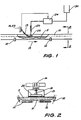
- the apparatus includes a grain conveyor 10 of a type which is suitable for transporting grain 11 from a freight car to a silo bucket elevator.
- the conveyor 10 is carried by support rollers 12 and by a frame structure (not shown) which carries the rollers.
- the apparatus which is employed for applying the protectant solution to the grain is mounted above the conveyor and comprises a flap device 13 which extends downwardly from a mounting structure 14.
- the flap device 13 projects forwardly of the structure 14 in the direction of movement of the conveyor, the conveyor movement direction being indicated by the arrow 15 in Figure 1.
- the flap device 13 is formed from a flexible resilient sheet material such as a synthetic rubber or polyurethane and it has a width less than that of the conveyor 10. Typically the width of the flap device 13 will be equal to one third of the width of the conveyor.
- the upper surface of the flap device 13 is clad at one end with a sheet of metal 16, such as stainless steel or aluminium, which serves to maintain that end of the flap device in a flat condition.
- a metal weight in the form of a steel bar 17 is secured to the free end of the flap device and serves to hold the device against the surface of the grain during passage of the conveyor.
- a metal rod 18 is connected to the sheet 16 by way of a mounting block 19, and the rod 18 is connected to a rotatable shaft 20 which is carried by the mounting structure 14.
- the rod 18 is connected to the upper end 21 of the flap device 13 by way of a U-bolt 22, which facilitates relative movement between the rod and the upper end of the flap device.
- the complete flap device is pivotable about the axis of rotation of the shaft 20.
- an electrical control device e.g. a potentiometer
- a pump 24 e.g. a pump
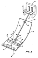
- the flap device 13 extends downwardly from the mounting structure 14 and, in the absence of any grain on the conveyor, the flap device assumes a lower pivotal position.
- a helical tension spring may be used to support the lower end of the flap such that it is held a few millimetres above the level of the conveyor when no material is actually being carried by the conveyor. The spring serves to protect the underside of the flap device and the conveyor from excessive wear when the conveyor is running and no material is carried by the conveyor.
- the flap device When grain is present on the conveyor, the flap device pivots upwardly to overlay the upper surface of the grain. In pivoting upwardly, the flap device 13 functions to sense the presence of grain on the conveyor and initiates actuation of the pump 24.
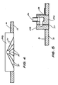
- a distributor 25 is mounted to the flap device 13 and extends across the device in the direction transverse to the direction of travel of the conveyor.
- the distributor 25 comprises a two-part metal bar-like structure 25 a , b and it includes a central inlet port 26 and a series of downwardly extending distributor channels 27.
- the distributor 25 is recessed into the flap device 13, such that the distributor channels open to the underside of the flap device.
- the bottom of distributor 25 lies flush with the underside of the flap device 13 and fluid which is forced through the distributor channels 27 is actually wiped onto the surface of the grain that is contacted by the flap device.
- An L-shaped mounting bracket 28 is employed for mounting the distributor to the flap device.
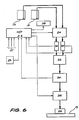
- a liquid delivery line 29 connects with the inlet port 26 and serves to provide the distributor 25 with liquid from a reservoir 30 (as indicated in Figure 1) or from a plurality of drums 31 (as indicated in Figure 6).
- two different concentrate liquids for example two insecticides which provide for broad spectrum protection, are drawn from the two drums 31 by the perastaltic pump 24.
- the desired mix ratio of the two liquids is determined by the relative ratio of occluded volumes of the tubes that are used to carry the liquids to and through the pump 24.
- the two liquids are directed through respective flowmeters 32, into a mixing chamber 33, and thereafter through a pressure transducer 34.
- the pressure transducer serves to detect for excessive back pressure within the circuit and, thus, to sense the presence of any blockage in the line 29.
- the blended liquids flow through a solenoid actuated valve 39 and then to the distributor 25.
- the solenoid valve is energised to preclude residual fluid flow when grain is sensed to be not present on the conveyor.
- Control of the pump 24 is effected by a microprocessor 36, with inputs to the microprocessor being derived from the control device 23, the flowmeters 32 and the pressure transducer 34.
- Other inputs 37 which are not specifically indicated in Figure 6, are fed to the microprocessor to provide a measure of the conveyor velocity, the load on the conveyor and the insecticide dosing requirements for the grain.
- An alarm device 38 may also be incorporated in the circuit to provide for visual and/or audible indication of blockages or other malfunctions in the system.
Landscapes
- Life Sciences & Earth Sciences (AREA)
- Soil Sciences (AREA)
- Environmental Sciences (AREA)
- Food Science & Technology (AREA)
- Engineering & Computer Science (AREA)
- Insects & Arthropods (AREA)
- Pest Control & Pesticides (AREA)
- Wood Science & Technology (AREA)
- Zoology (AREA)
- Catching Or Destruction (AREA)
Claims (9)
- Appareil pour appliquer un fluide à un matériau qui est porté par un convoyeur (10), l'appareil comprenant un dispositif à volet (13) situé au voisinage du convoyeur et disposé de manière à venir en contact avec le matériau (11) porté ou évacué par le convoyeur; un distributeur (25) agencé de manière à diriger le fluide à l'intérieur du matériau (11), qui vient en contact avec le dispositif à volet (13) lors de l'utilisation de l'appareil, et dans lequel il est prévu des moyens (29) servant à délivrer le fluide au distributeur (25), des moyens (23) pour détecter l'existence d'un matériau sur le convoyeur (10) et admettre le fluide dans le distributeur (25) en réponse à la détection de la présence du matériau sur le convoyeur, caractérisé en ce que le distributeur (25) est monté sur le dispositif à volet (13) et s'étend en sur au moins une partie de l'étendue en largeur du dispositif à volet (13).
- Appareil selon la revendication 1, caractérisé en outre en ce que le dispositif à volet (13) est situé au-dessus du convoyeur (10) et est disposé de manière à recouvrir le convoyeur, le matériau (11) situé sur le convoyeur venant en contact avec la face inférieure du dispositif à volet.
- Appareil selon la revendication 2, caractérisé en outre en ce que le dispositif à volet (13) est monté pivotant, au niveau de l'une de ses extrémités, sur une structure de support (14), et en ce qu'il est prévu des moyens (23) pour détecter le mouvement de pivotement du dispositif à volet (13) et détecter de ce fait la présence d'un matériau sur le convoyeur.
- Appareil selon la revendication 3, caractérisé en outre en ce que le dispositif à volet (13) est constitué au moins en partie par une feuille d'un matériau élastique flexible, et en ce que la structure de support (14) est disposée au-dessus du convoyeur de telle sorte que le dispositif à volet suit un trajet courbe descendant à partir de la structure de support en direction du convoyeur.
- Appareil selon la revendication 4, caractérisé en outre en ce que la surface supérieure d'une partie d'extrémité du dispositif à volet (13), qui est distante de la structure de support (14), est recouverte par une feuille plane (16) formée d'un matériau relativement rigide, ce qui a pour effet qu'une partie d'extrémité du dispositif à volet est maintenue dans un état sensiblement plat.
- Appareil selon la revendication 5, caractérisé en outre en ce que le dispositif à volet (13) est monté pivotant sur la structure de support par l'intermédiaire d'une tige (10a), qui est raccordée, par une extrémité, à la feuille plane (16) et est également raccordée, par une première extrémité du dispositif à volet, par des moyens (22) permettant un déplacement relatif entre la tige et ladite première extrémité du dispositif à volet.
- Appareil selon l'une quelconque des revendications précédentes, caractérisé en outre en ce que le distributeur (25) comprend une série de canaux de distribution (27) qui s'ouvrent au niveau d'un bord du distributeur, qui est sensiblement de niveau avec la surface inférieure du dispositif à volet.
- Appareil selon la revendication 7, caractérisé en outre en ce que le distributeur (25) est monté de façon amovible dans un renfoncement ménagé dans le dispositif à volet.
- Procédé pour appliquer un fluide à un matériau en vrac (11) porté par un convoyeur (10), et selon lequel le fluide est dirigé à l'intérieur du matériau (11) par l'intermédiaire d'un distributeur (25), un dispositif à volet pivotant étant dispose au voisinage du convoyeur (10) et positionné de manière à venir en contact avec le matériau porté ou délivré par le convoyeur, et le fluide est envoyé au distributeur (25) en réponse à la détection de la présence du matériau sur le convoyeur, caractérisé en ce que le distributeur (25) est monté sur le dispositif à volet pivotant (13).
Priority Applications (1)
| Application Number | Priority Date | Filing Date | Title |
|---|---|---|---|
| AT87308326T ATE69353T1 (de) | 1986-09-22 | 1987-09-21 | Verfahren und vorrichtung, um eine fluessigkeit auf schuettguetern anzubringen. |
Applications Claiming Priority (3)
| Application Number | Priority Date | Filing Date | Title |
|---|---|---|---|
| AUPH814286 | 1986-09-22 | ||
| AU8142/86 | 1986-09-22 | ||
| AU78443/87A AU592893B2 (en) | 1986-09-22 | 1987-09-15 | Method of and apparatus for applying a fluid to a bulk commodity |
Publications (3)
| Publication Number | Publication Date |
|---|---|
| EP0261908A2 EP0261908A2 (fr) | 1988-03-30 |
| EP0261908A3 EP0261908A3 (en) | 1988-08-31 |
| EP0261908B1 true EP0261908B1 (fr) | 1991-11-13 |
Family
ID=25638920
Family Applications (1)
| Application Number | Title | Priority Date | Filing Date |
|---|---|---|---|
| EP19870308326 Expired EP0261908B1 (fr) | 1986-09-22 | 1987-09-21 | Méthode et appareil pour appliquer un liquide à un matériau en vrac |
Country Status (1)
| Country | Link |
|---|---|
| EP (1) | EP0261908B1 (fr) |
Family Cites Families (4)
| Publication number | Priority date | Publication date | Assignee | Title |
|---|---|---|---|---|
| DE261896C (fr) * | ||||
| US3138482A (en) * | 1961-09-14 | 1964-06-23 | American Cyanamid Co | Peanut flocontrol sprayer |
| GB1395988A (en) * | 1972-10-26 | 1975-05-29 | Armour Moore Marine Service | Surface treatment |
| DE3171477D1 (en) * | 1980-05-28 | 1985-08-29 | Gaston Laury | Apparatus for applying a viscous liquid and in particular an adhesive mixture to a support, and a device provided with such an apparatus |
-
1987
- 1987-09-21 EP EP19870308326 patent/EP0261908B1/fr not_active Expired
Also Published As
| Publication number | Publication date |
|---|---|
| EP0261908A3 (en) | 1988-08-31 |
| EP0261908A2 (fr) | 1988-03-30 |
Similar Documents
| Publication | Publication Date | Title |
|---|---|---|
| CA1316506C (fr) | Appareil de pulverisation de liquide | |
| US4742228A (en) | Infrared measuring apparatus and process for the continuous quantitative determination of individual components of flour or other groundable food products | |
| EP0582747B1 (fr) | Dispositif pour le traitement de céréales | |
| JPH08505281A (ja) | 密封散布容器のための電磁計量器 | |
| US4714196A (en) | Farm chemical delivery system | |
| EP0397950B1 (fr) | Appareil de conditionnement de céréales fourragères | |
| US6395091B1 (en) | Process and system for coating a feed composition with a feed additive | |
| US4797301A (en) | Method of and apparatus for applying a fluid to a bulk commodity | |
| JP3750068B2 (ja) | 粒状物質に水分を添加するための方法及び装置 | |
| CA1264788A (fr) | Dispositif et methode de transport pneumatique de materiaux granules | |
| WO2020033861A2 (fr) | Système de distribution d'agent de soutènement | |
| EP1905935A3 (fr) | Distribution contrôlée de matériel | |
| CA2877860C (fr) | Poste de traitement de semences a profil bas ayant une fonction de dosage | |
| EP0757232A3 (fr) | Dispositif et procédé pour arranger et contrÔler la déposition de matériaux sur une surface | |
| NL8501365A (nl) | Werkwijze en inrichting voor het verspuiten van een vloeistof. | |
| US6981619B2 (en) | High precision metering and/or additioning device, particularly for granular materials | |
| US5269463A (en) | Fluidized powder feed system with pressurized hopper | |
| DE60114445T2 (de) | Vorrichtung zum aromatisieren | |
| NL8101615A (nl) | Verdeelinrichting. | |
| EP0523181A1 (fr) | Appareil de sablage ameliore | |
| EP0261908B1 (fr) | Méthode et appareil pour appliquer un liquide à un matériau en vrac | |
| AU592893B2 (en) | Method of and apparatus for applying a fluid to a bulk commodity | |
| EP0407440A1 (fr) | Preparation de melanges de liquides. | |
| US3279423A (en) | Fruit treating apparatus and control means therefor | |
| AU762456B2 (en) | Spraying equipment |
Legal Events
| Date | Code | Title | Description |
|---|---|---|---|
| PUAI | Public reference made under article 153(3) epc to a published international application that has entered the european phase |
Free format text: ORIGINAL CODE: 0009012 |
|
| 17P | Request for examination filed |
Effective date: 19870928 |
|
| AK | Designated contracting states |
Kind code of ref document: A2 Designated state(s): AT BE CH DE ES FR GB GR IT LI LU NL SE |
|
| PUAL | Search report despatched |
Free format text: ORIGINAL CODE: 0009013 |
|
| AK | Designated contracting states |
Kind code of ref document: A3 Designated state(s): AT BE CH DE ES FR GB GR IT LI LU NL SE |
|
| 17Q | First examination report despatched |
Effective date: 19900522 |
|
| GRAA | (expected) grant |
Free format text: ORIGINAL CODE: 0009210 |
|
| AK | Designated contracting states |
Kind code of ref document: B1 Designated state(s): AT BE CH DE ES FR GB GR IT LI LU NL SE |
|
| PG25 | Lapsed in a contracting state [announced via postgrant information from national office to epo] |
Ref country code: IT Free format text: LAPSE BECAUSE OF FAILURE TO SUBMIT A TRANSLATION OF THE DESCRIPTION OR TO PAY THE FEE WITHIN THE PRE;WARNING: LAPSES OF ITALIAN PATENTS WITH EFFECTIVE DATE BEFORE 2007 MAY HAVE OCCURRED AT ANY TIME BEFORE 2007. THE CORRECT EFFECTIVE DATE MAY BE DIFFERENT FROM THE ONE RECORDED.SCRIBED TIME-LIMIT Effective date: 19911113 Ref country code: LI Effective date: 19911113 Ref country code: NL Effective date: 19911113 Ref country code: SE Effective date: 19911113 Ref country code: AT Effective date: 19911113 Ref country code: CH Effective date: 19911113 Ref country code: BE Effective date: 19911113 Ref country code: GR Free format text: LAPSE BECAUSE OF FAILURE TO SUBMIT A TRANSLATION OF THE DESCRIPTION OR TO PAY THE FEE WITHIN THE PRESCRIBED TIME-LIMIT Effective date: 19911113 |
|
| REF | Corresponds to: |
Ref document number: 69353 Country of ref document: AT Date of ref document: 19911115 Kind code of ref document: T |
|
| REF | Corresponds to: |
Ref document number: 3774522 Country of ref document: DE Date of ref document: 19911219 |
|
| ET | Fr: translation filed | ||
| PG25 | Lapsed in a contracting state [announced via postgrant information from national office to epo] |
Ref country code: ES Free format text: LAPSE BECAUSE OF FAILURE TO SUBMIT A TRANSLATION OF THE DESCRIPTION OR TO PAY THE FEE WITHIN THE PRESCRIBED TIME-LIMIT Effective date: 19920224 |
|
| REG | Reference to a national code |
Ref country code: CH Ref legal event code: PL |
|
| NLV1 | Nl: lapsed or annulled due to failure to fulfill the requirements of art. 29p and 29m of the patents act | ||
| PLBE | No opposition filed within time limit |
Free format text: ORIGINAL CODE: 0009261 |
|
| STAA | Information on the status of an ep patent application or granted ep patent |
Free format text: STATUS: NO OPPOSITION FILED WITHIN TIME LIMIT |
|
| PG25 | Lapsed in a contracting state [announced via postgrant information from national office to epo] |
Ref country code: LU Free format text: LAPSE BECAUSE OF NON-PAYMENT OF DUE FEES Effective date: 19920930 |
|
| 26N | No opposition filed | ||
| PG25 | Lapsed in a contracting state [announced via postgrant information from national office to epo] |
Ref country code: DE Effective date: 19930602 |
|
| REG | Reference to a national code |
Ref country code: FR Ref legal event code: TP |
|
| REG | Reference to a national code |
Ref country code: GB Ref legal event code: 732E |
|
| REG | Reference to a national code |
Ref country code: FR Ref legal event code: CA Ref country code: FR Ref legal event code: CD |
|
| REG | Reference to a national code |
Ref country code: GB Ref legal event code: IF02 |
|
| PGFP | Annual fee paid to national office [announced via postgrant information from national office to epo] |
Ref country code: FR Payment date: 20020910 Year of fee payment: 16 |
|
| PGFP | Annual fee paid to national office [announced via postgrant information from national office to epo] |
Ref country code: GB Payment date: 20020918 Year of fee payment: 16 |
|
| PG25 | Lapsed in a contracting state [announced via postgrant information from national office to epo] |
Ref country code: GB Free format text: LAPSE BECAUSE OF NON-PAYMENT OF DUE FEES Effective date: 20030921 |
|
| GBPC | Gb: european patent ceased through non-payment of renewal fee |
Effective date: 20030921 |
|
| PG25 | Lapsed in a contracting state [announced via postgrant information from national office to epo] |
Ref country code: FR Free format text: LAPSE BECAUSE OF NON-PAYMENT OF DUE FEES Effective date: 20040528 |
|
| REG | Reference to a national code |
Ref country code: FR Ref legal event code: ST |