EP0261587A2 - Passiv aerodynamisches Druckminderungssystem - Google Patents
Passiv aerodynamisches Druckminderungssystem Download PDFInfo
- Publication number
- EP0261587A2 EP0261587A2 EP87113580A EP87113580A EP0261587A2 EP 0261587 A2 EP0261587 A2 EP 0261587A2 EP 87113580 A EP87113580 A EP 87113580A EP 87113580 A EP87113580 A EP 87113580A EP 0261587 A2 EP0261587 A2 EP 0261587A2
- Authority
- EP
- European Patent Office
- Prior art keywords
- mitigation system
- passive
- pivot axis
- load mitigation
- aerodynamic
- Prior art date
- Legal status (The legal status is an assumption and is not a legal conclusion. Google has not performed a legal analysis and makes no representation as to the accuracy of the status listed.)
- Granted
Links
- 230000000116 mitigating effect Effects 0.000 title claims abstract description 38
- 239000012530 fluid Substances 0.000 claims abstract description 9
- 238000005452 bending Methods 0.000 claims abstract description 6
- 239000011152 fibreglass Substances 0.000 claims description 7
- 238000000034 method Methods 0.000 description 5
- 238000013459 approach Methods 0.000 description 3
- 238000010420 art technique Methods 0.000 description 3
- 230000003068 static effect Effects 0.000 description 3
- 238000006880 cross-coupling reaction Methods 0.000 description 2
- CWYNVVGOOAEACU-UHFFFAOYSA-N Fe2+ Chemical compound [Fe+2] CWYNVVGOOAEACU-UHFFFAOYSA-N 0.000 description 1
- 230000002411 adverse Effects 0.000 description 1
- 230000008878 coupling Effects 0.000 description 1
- 238000010168 coupling process Methods 0.000 description 1
- 238000005859 coupling reaction Methods 0.000 description 1
- 230000003111 delayed effect Effects 0.000 description 1
- 238000009434 installation Methods 0.000 description 1
- 230000003534 oscillatory effect Effects 0.000 description 1
- 230000001629 suppression Effects 0.000 description 1
- 238000011144 upstream manufacturing Methods 0.000 description 1
Images

Classifications
-
- G—PHYSICS
- G01—MEASURING; TESTING
- G01M—TESTING STATIC OR DYNAMIC BALANCE OF MACHINES OR STRUCTURES; TESTING OF STRUCTURES OR APPARATUS, NOT OTHERWISE PROVIDED FOR
- G01M9/00—Aerodynamic testing; Arrangements in or on wind tunnels
- G01M9/06—Measuring arrangements specially adapted for aerodynamic testing
Definitions
- the present invention relates to apparatus for installing external electromagnetic transducers on an aircraft and more particularly to a passive aerodynamic load mitigation system for supporting such transducers in an aerodynamically-stable fashion on the aircraft.
- a passive aerodynamic load mitigation system for supporting electromagnetic transducers on a body, e.g., an aircraft, moving through a fluid stream.
- a streamlined surface is used to support the electromagnetic transducers, the surface having a base portion, a top portion, and first and second symmetrical sidewall portions of substantially trapezoidal or parallelogram shape.
- a pivot axis has a first end attached to the body and a second end attached to the base of the surface to enable the surface to rotate about the pivot axis.
- the pivot axis supports the streamlined surface in a torsionally unrestrained manner in preferably one rotational degree of freedom about the pivot axis.
- the streamlined surface remains substantially parallel to the plane of the fluid stream. Aerodynamical stability is maintained by mounting the surface on the pivot axis such that its aerodynamic center is located downstream from the axis. Flutter is prevented or substantially reduced by increasing the surface's bending stiffness or by incorporating suitable ballast weights on a tip pod attached to the top portion of the surface.
- FIGURE 1 is a perspective view of the preferred passive load mitigation system of the present invention.
- the load mitigation system is designed to support one or more external electromagnetic transducers 10 on an aircraft fuselage 12 moving through an airstream 14.
- the transducers i.e., electromagnetic emitters and sensors
- the transducers are housed in or on an aerodynamically streamlined surface or housing 16 which is constructed and attached to the aircraft fuselage 12 in a manner to to be described.
- the passive aerodynamic load mitigation system of the present invention overcomes the disadvantages associated with prior techniques by providing a streamlined surface or housing 16 which is unrestrained in at least one of its rotational degrees of freedom as will be described.
- dynamic stability is most readily achieved by maintaining the surface 16 unrestrained in just one rotational degree of freedom as will be described.
- the streamlined surface 16 includes a base portion 18, a top portion 20 parallel thereto, and first and second symmetric sidewall portions 22 and 24.
- the first symmetric sidewall portion 22 includes a front edge 26 and a rear edge 28.
- the second symmetric sidewall portion 24 includes a front edge 30 and a rear edge 32.
- the front edges 26 and 30 of the first and second sidewall portions 22 and 24 are joined together to ensure that the leading surface of housing 16 is aerodynamically-streamlined.
- the rear edges 28 and 32 of the first and second sidewall portions 22 and 24 are also joined together.
- the surface 16 comprises a fiberglass honeycomb core with a bonded fiberglass outer skin.
- the streamlined surface 16 is designed to dynamically align itself Parallel to the incident airstream through the use of a pivot axis 34 which supports the surface 16 on the aircraft fuselage 12.
- the pivot axis 34 which preferably is formed of a thick-walled hollow fiberglass or non-ferrous metallic tube, includes a first end 36 attached to the aircraft fuselage and a second end 38 embedded in the honeycomb core of the surface 16.
- portions of the front edges 26 and 30 of the surface 16 adjacent the fuselage 12 are located "upstream" of the pivot axis while the rear edges 28 and 32 are located “downstream” of the axis.
- the second end 38 of the pivot axis 34 is connected to the surface 16 via any suitable low friction bearing mechanism.
- a mechanism allows the surface 16 to freely pivot about a z-z rotational axis shown in FIGURE 1.
- the second end 38 of the pivot axis 34 may be permanently secured to the surface 16 or an integral extension thereof, in which case the first end 36 of the pivot axis 34 is rotatably-secured to the aircraft fuselage by the bearing mechanism.
- pivot axis 34 allows the streamlined surface 16 to be torsionally unrestrained in the z-z rotational degree of freedom.
- This degree of freedom is one which allows the surface 16 to dynamically orient itself so as to always lie parallel to the plane of the airstream 14. Accordingly, because the surface is symmetrical and aligns itself parallel to the airstream, the steady state "angle of attack" of the surface 16 is always zero, regardless of the orientation of the aircraft 12 relative to the airstream. Because the steady state angle of attack is zero, net steady state airloads normal to the surface 16 are also zero. The system therefore operates to passively mitigate airloads which would otherwise adversely affect the stability of the surface and the aircraft.
- each of the first and second symmetric sidewall portions 22 and 24 of the surface 16 has a substantially trapezoidal shape.
- the base portion 18 preferably has a marquis-shaped structure, as does the top portion 20. While this geometry is preferred, it is not meant to be limiting, as other equivalent geometrical structures may also be used.
- Static aeroelastic stability of the surface 16 is maintained by locating the pivot axis 34 such that a chordwise (i.e., a straight line joining the front and rear edges of the surface) location of the aerodynamic center of the surface 16 always lies downstream of the pivot axis.
- the "aerodynamic center" of any configuration can be determined by wind tunnel tests or, alternatively, can be established accurately using aerodynamic analysis techniques such as doublet lattice theory. This latter analysis technique determines the real part of a generalized force in the rigid body pitch mode as a function of the chordwise pivot axis location. The pivot axis chordwise location at which the pitch mode generalized force vanishes then defines the aerodynamic center of the configuration. Once this predetermined aerodynamic center is located, the surface 16 is supported on the pivot axis 34 such that this center is located downstream from the axis 34.
- dynamic aeroelastic instability is Prevented or substantially reduced by one of two preferred approaches.
- Flutter is a self-excited instability involving aerodynamic coupling between two or more modes of motion of the system.
- Classical flutter is typically caused by an energy transfer from the airstream to the structure and is manifested by violent oscillatory motion usually terminating in catastrophic structural failure.
- the degree of overall torsional rigidity is one of the primary factors which determines the flutter speed of a lifting surface.
- flutter speed onset is delayed by increasing the bending stiffness of the surface 16.
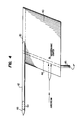
- FIGURE 4 is a side elevational view of a alternative embodiment of the system of FIGURES 1-3
- an aerodynamically streamlined surface 40 has a substantially parallelogram shape and incorporates a tip pod 42 structurally attached to the top surface 20 thereof. Tip pod 42 is also structurally attached to an embedded mast 44 such that the total system acts as one structural unit.
- a lower extension 46 of the mast 44 constitutes a pivot axis about which the system is free to rotate as described above with respect to the system disclosed in FIGURES 1-3.
- the pivot axis 46 is supported by a low friction bearing mechanism (not shown) located interior to the aircraft skin.
- the tip pod 42 includes a distal end 48 which supports one or more ballast weights 50.
- the ballast weights 50 are mounted interior to and substantially near the distal end 48 of the tip pod 42.
- the ballast weights 50 have inertial values determined by mathematical modeling procedures, such as flutter analysis, and these weights are geometrically located on the tip pod 42 such that an otherwise self-excited aeroelastic instability of the system is suppressed. Such suppression occurs as a result of dynamic inertial cross-coupling between two or more modes of motion of the system.
- FIGURE 4 While the structure of FIGURE 4 is preferred, it should be appreciated that the specific structure of the tip pod and/or the location of the tip pod 42 with respect to the top portion 20 of the surface 40 are not meant to be limiting.
- the tip pod (or equivalent) structure may be suitably rearranged so long as the ballast weights or equivalent structure have the proper inertial values and are geometrically located on the system such that an otherwise self-excited aeroelastic instability of the system is suppressed through dynamic inertial cross-coupling between two or more modes of motion of the system.
- the passive aerodynamic load mitigation system of the present invention advantageously supports external electromagnetic transducers on an aircraft in an aerodynamically stable fashion. This operation is achieved by using a streamlined surface which is torsionally unrestrained in one of its rotational degree of freedom, i.e., the degree of freedom which allows the surface to dynamically orient itself so as to always lie parallel to the plane of the airstream. Moreover, static aeroelastic stability of the surface 16 is maintained by selecting a substantially trapezoidal or parallelogram aerodynamic configuration for the sidewall portions of the surface, and by selecting a pivot axis location such that the chordwise location of the aerodynamic center of the surface always lies downstream of the pivot axis.
- Dynamic aeroelastic instability is then prevented or substantially reduced by increasing the bending stiffness of the surface 16 or by incorporating suitable ballast weights on an integral tip pod or like structure as shown in FIGURE 4.
- the system results in aerodynamic and structural impact on the basic aircraft which is significantly reduced as compared to equivalent conventional installations of transducer housings on aircraft.
- the basic operating principles of the passive aerodynamic load mitigation system of the invention may also be used to support any type of transducer on a body moving through a fluid stream. Accordingly, the scope of the present invention is not deemed limited to the use of the system for supporting external electromagnetic transducers on an aircraft.
Landscapes
- Physics & Mathematics (AREA)
- Fluid Mechanics (AREA)
- General Physics & Mathematics (AREA)
- Details Of Aerials (AREA)
- Aerodynamic Tests, Hydrodynamic Tests, Wind Tunnels, And Water Tanks (AREA)
Applications Claiming Priority (2)
| Application Number | Priority Date | Filing Date | Title |
|---|---|---|---|
| US91008586A | 1986-09-22 | 1986-09-22 | |
| US910085 | 2001-07-20 |
Publications (3)
| Publication Number | Publication Date |
|---|---|
| EP0261587A2 true EP0261587A2 (de) | 1988-03-30 |
| EP0261587A3 EP0261587A3 (en) | 1988-07-20 |
| EP0261587B1 EP0261587B1 (de) | 1992-06-03 |
Family
ID=25428288
Family Applications (1)
| Application Number | Title | Priority Date | Filing Date |
|---|---|---|---|
| EP87113580A Expired - Lifetime EP0261587B1 (de) | 1986-09-22 | 1987-09-17 | Passiv aerodynamisches Druckminderungssystem |
Country Status (4)
| Country | Link |
|---|---|
| EP (1) | EP0261587B1 (de) |
| CA (1) | CA1301733C (de) |
| DE (1) | DE3779536T2 (de) |
| IL (1) | IL83924A (de) |
Cited By (5)
| Publication number | Priority date | Publication date | Assignee | Title |
|---|---|---|---|---|
| EP0341447A3 (de) * | 1988-05-11 | 1991-04-10 | Daimler-Benz Aktiengesellschaft | Vorrichtung zur Bestimmung von Seitenwindeinflüssen an Fahrzeugen |
| CN110160732A (zh) * | 2018-08-09 | 2019-08-23 | 北京机电工程研究所 | 用于颤振试验的可调摩擦力装置及可调摩擦力方法 |
| CN111003208A (zh) * | 2019-12-06 | 2020-04-14 | 江西洪都航空工业集团有限责任公司 | 一种飞机减速板非线性力加载试验装置 |
| CN111307396A (zh) * | 2019-11-29 | 2020-06-19 | 厦门大学 | 一种风洞虚拟飞行试验的模型支撑结构、装置和系统 |
| GB2568356B (en) * | 2017-09-07 | 2021-12-15 | Borealis Tech Ltd | Improved aircraft ground collision avoidance system |
Family Cites Families (6)
| Publication number | Priority date | Publication date | Assignee | Title |
|---|---|---|---|---|
| US2081957A (en) * | 1933-09-01 | 1937-06-01 | Roche Jean Alfred | Dynamic balance of control surfaces |
| US3882721A (en) * | 1973-11-16 | 1975-05-13 | Rosemount Inc | Vane type airflow sensor |
| US4178667A (en) * | 1978-03-06 | 1979-12-18 | General Motors Corporation | Method of controlling turbomachine blade flutter |
| US4188823A (en) * | 1978-11-27 | 1980-02-19 | The United States Of America As Represented By The Administrator Of The National Aeronautics And Space Administration | Detection of the transitional layer between laminar and turbulent flow areas on a wing surface |
| US4207764A (en) * | 1979-03-05 | 1980-06-17 | The United States Of America As Represented By The Secretary Of The Air Force | Precision fin indexing device for wind tunnel models |
| US4372157A (en) * | 1981-04-07 | 1983-02-08 | General Motors Corporation | Aerodynamic data collection procedure |
-
1987
- 1987-08-13 CA CA000544465A patent/CA1301733C/en not_active Expired - Fee Related
- 1987-09-16 IL IL83924A patent/IL83924A/xx unknown
- 1987-09-17 DE DE8787113580T patent/DE3779536T2/de not_active Expired - Fee Related
- 1987-09-17 EP EP87113580A patent/EP0261587B1/de not_active Expired - Lifetime
Cited By (5)
| Publication number | Priority date | Publication date | Assignee | Title |
|---|---|---|---|---|
| EP0341447A3 (de) * | 1988-05-11 | 1991-04-10 | Daimler-Benz Aktiengesellschaft | Vorrichtung zur Bestimmung von Seitenwindeinflüssen an Fahrzeugen |
| GB2568356B (en) * | 2017-09-07 | 2021-12-15 | Borealis Tech Ltd | Improved aircraft ground collision avoidance system |
| CN110160732A (zh) * | 2018-08-09 | 2019-08-23 | 北京机电工程研究所 | 用于颤振试验的可调摩擦力装置及可调摩擦力方法 |
| CN111307396A (zh) * | 2019-11-29 | 2020-06-19 | 厦门大学 | 一种风洞虚拟飞行试验的模型支撑结构、装置和系统 |
| CN111003208A (zh) * | 2019-12-06 | 2020-04-14 | 江西洪都航空工业集团有限责任公司 | 一种飞机减速板非线性力加载试验装置 |
Also Published As
| Publication number | Publication date |
|---|---|
| CA1301733C (en) | 1992-05-26 |
| EP0261587B1 (de) | 1992-06-03 |
| DE3779536T2 (de) | 1993-05-19 |
| IL83924A0 (en) | 1988-02-29 |
| EP0261587A3 (en) | 1988-07-20 |
| DE3779536D1 (de) | 1992-07-09 |
| IL83924A (en) | 1992-12-01 |
Similar Documents
| Publication | Publication Date | Title |
|---|---|---|
| US11174019B2 (en) | VTOL M-wing configuration | |
| US5131604A (en) | Helicopter antitorque device | |
| US9533768B2 (en) | Aircraft engine mounting system | |
| JP4405704B2 (ja) | ロータ傾斜型転換式航空機における改良 | |
| US4514143A (en) | Aircraft rotor blade with passive tuned tab | |
| US4231536A (en) | Airfoil for controlling refueling boom | |
| EP0780292A1 (de) | Verfahren zur Ausrichtung der Rollachse einer Luftbetankungssonde | |
| EP4214120B1 (de) | Flugzeugstruktur | |
| EP1031507A2 (de) | Abgestimmte Jettriebwerks- Befestigungsvorrichtung | |
| JPH08509930A (ja) | ダクト付きカウンタ回転同軸ロータを有する無人飛行体の空力的補助構造体 | |
| US20040075017A1 (en) | Control of an aircraft as a thrust-vectored pendulum in vertical, horizontal and all flight transitional modes thereof | |
| AU2007347147A1 (en) | Method and apparatus for retrieving a hovering aircraft | |
| EP0508026B1 (de) | Integrierte Leitwerkstruktur eines Hubschraubers | |
| JP2011046355A (ja) | 飛行体 | |
| US4804154A (en) | Passive aerodynamic load mitigation system | |
| US4616793A (en) | Remote pivot decoupler pylon: wing/store flutter suppressor | |
| EP0261587A2 (de) | Passiv aerodynamisches Druckminderungssystem | |
| US2949965A (en) | Rotor hub | |
| US20070280828A1 (en) | Blade having an integral cuff, and a rotorcraft rotor provided with such a blade | |
| JPH04328095A (ja) | メインローターユニット支持トラス | |
| CN208439425U (zh) | 一种新型复合式固定翼无人机 | |
| JP2018030390A (ja) | 回転翼および回転翼式飛行体 | |
| US20240239481A1 (en) | A system and a method of vibration mitigation for an propulsor and a boom in an electric aircraft | |
| US20210371117A1 (en) | Aircraft | |
| US20160319800A1 (en) | Strain isolated attachment for one-piece wind turbine rotor hub |
Legal Events
| Date | Code | Title | Description |
|---|---|---|---|
| PUAI | Public reference made under article 153(3) epc to a published international application that has entered the european phase |
Free format text: ORIGINAL CODE: 0009012 |
|
| AK | Designated contracting states |
Kind code of ref document: A2 Designated state(s): DE GB IT |
|
| PUAL | Search report despatched |
Free format text: ORIGINAL CODE: 0009013 |
|
| AK | Designated contracting states |
Kind code of ref document: A3 Designated state(s): DE GB IT |
|
| 17P | Request for examination filed |
Effective date: 19890113 |
|
| 17Q | First examination report despatched |
Effective date: 19900628 |
|
| GRAA | (expected) grant |
Free format text: ORIGINAL CODE: 0009210 |
|
| ITF | It: translation for a ep patent filed | ||
| AK | Designated contracting states |
Kind code of ref document: B1 Designated state(s): DE GB IT |
|
| REF | Corresponds to: |
Ref document number: 3779536 Country of ref document: DE Date of ref document: 19920709 |
|
| PLBE | No opposition filed within time limit |
Free format text: ORIGINAL CODE: 0009261 |
|
| STAA | Information on the status of an ep patent application or granted ep patent |
Free format text: STATUS: NO OPPOSITION FILED WITHIN TIME LIMIT |
|
| 26N | No opposition filed | ||
| PGFP | Annual fee paid to national office [announced via postgrant information from national office to epo] |
Ref country code: GB Payment date: 19930907 Year of fee payment: 7 |
|
| PGFP | Annual fee paid to national office [announced via postgrant information from national office to epo] |
Ref country code: DE Payment date: 19930908 Year of fee payment: 7 |
|
| PG25 | Lapsed in a contracting state [announced via postgrant information from national office to epo] |
Ref country code: GB Effective date: 19940917 |
|
| GBPC | Gb: european patent ceased through non-payment of renewal fee |
Effective date: 19940917 |
|
| PG25 | Lapsed in a contracting state [announced via postgrant information from national office to epo] |
Ref country code: DE Effective date: 19950601 |
|
| PG25 | Lapsed in a contracting state [announced via postgrant information from national office to epo] |
Ref country code: IT Free format text: LAPSE BECAUSE OF NON-PAYMENT OF DUE FEES;WARNING: LAPSES OF ITALIAN PATENTS WITH EFFECTIVE DATE BEFORE 2007 MAY HAVE OCCURRED AT ANY TIME BEFORE 2007. THE CORRECT EFFECTIVE DATE MAY BE DIFFERENT FROM THE ONE RECORDED. Effective date: 20050917 |