EP0261365A1 - Immersion lance - Google Patents
Immersion lance Download PDFInfo
- Publication number
- EP0261365A1 EP0261365A1 EP87111378A EP87111378A EP0261365A1 EP 0261365 A1 EP0261365 A1 EP 0261365A1 EP 87111378 A EP87111378 A EP 87111378A EP 87111378 A EP87111378 A EP 87111378A EP 0261365 A1 EP0261365 A1 EP 0261365A1
- Authority
- EP
- European Patent Office
- Prior art keywords
- inner tube
- lance according
- diving
- gases
- fin
- Prior art date
- Legal status (The legal status is an assumption and is not a legal conclusion. Google has not performed a legal analysis and makes no representation as to the accuracy of the status listed.)
- Granted
Links
Images
Classifications
-
- C—CHEMISTRY; METALLURGY
- C21—METALLURGY OF IRON
- C21C—PROCESSING OF PIG-IRON, e.g. REFINING, MANUFACTURE OF WROUGHT-IRON OR STEEL; TREATMENT IN MOLTEN STATE OF FERROUS ALLOYS
- C21C5/00—Manufacture of carbon-steel, e.g. plain mild steel, medium carbon steel or cast steel or stainless steel
- C21C5/28—Manufacture of steel in the converter
- C21C5/42—Constructional features of converters
- C21C5/46—Details or accessories
- C21C5/4606—Lances or injectors
- C21C5/4613—Refractory coated lances; Immersion lances
-
- C—CHEMISTRY; METALLURGY
- C21—METALLURGY OF IRON
- C21C—PROCESSING OF PIG-IRON, e.g. REFINING, MANUFACTURE OF WROUGHT-IRON OR STEEL; TREATMENT IN MOLTEN STATE OF FERROUS ALLOYS
- C21C1/00—Refining of pig-iron; Cast iron
- C21C1/08—Manufacture of cast-iron
Landscapes
- Engineering & Computer Science (AREA)
- Chemical & Material Sciences (AREA)
- Manufacturing & Machinery (AREA)
- Materials Engineering (AREA)
- Metallurgy (AREA)
- Organic Chemistry (AREA)
- Refinement Of Pig-Iron, Manufacture Of Cast Iron, And Steel Manufacture Other Than In Revolving Furnaces (AREA)
- Treatment Of Steel In Its Molten State (AREA)
Abstract
Die Erfindung betrifft eine Tauchlanze zum Einbringen von Behandlungsmedien, wie Gasen, insbesondere inerten Gase und/oder Trägergasen, mit denen Feststoffe, wie schlackenbildende Stoffe, Kohlenstoff oder dgl. transportiert werden, in einen mit flüssigem Metall gefüllten Behälter, insbesondere zur Behandlung von Roheisen oder Stahl. Die Tauchlanze besteht aus einem metallenen Innenrohr für die Zufuhr des Mediums und einer feuerfesten monolithischen keramischen Ummantelung, die mittels einer am Innenrohr anliegenden Armierung gehalten ist, und einer oder mehreren die Ummantelung durchdringenden Auslauföffnungen. Kennzeichen der Erfindung ist, daß die das Innenrohr (2) umgebende Armierung aus mindestens einem spiralförmig gewickelten Rippenband (9) gebildet ist, das Rippenteile (10) mit gleichmäßigen Abständen (11) bildet und mit dem Innenrohr (2) verbunden ist.The invention relates to a submersible lance for introducing treatment media, such as gases, in particular inert gases and / or carrier gases, with which solids, such as slag-forming substances, carbon or the like, are transported into a container filled with liquid metal, in particular for the treatment of pig iron or Stole. The immersion lance consists of a metal inner tube for the supply of the medium and a refractory monolithic ceramic jacket, which is held by means of a reinforcement attached to the inner tube, and one or more outlet openings penetrating the jacket. The invention is characterized in that the reinforcement surrounding the inner tube (2) is formed from at least one spirally wound ribbed belt (9), which forms ribbed parts (10) at uniform intervals (11) and is connected to the inner tube (2).
Description
Die Erfindung betrifft eine Tauchlanze zum Einbringen von Behandlungsmedien, wie Gasen insbesondere inerten Gase und/oder Trägergasen, mit denen Feststoffe, wie schlackenbildende Stoffe, Kohlenstoff oder dgl. transportiert werden, in einen mit Metall gefüllten Behälter, insbesondere zur Behandlung von Roheisen oder Stahl. Die Tauchlanze besteht aus einem metallenen Innenrohr für die Zufuhr des Mediums und einer feuerfesten monolithischen keramischen Ummantelung, die mittels einer am Innenrohr anliegenden Armierung gehalten ist, und einer oder mehreren die Ummantelung durchdringenden Auslauföffnungen.The invention relates to a submersible lance for introducing treatment media, such as gases, in particular inert gases and / or carrier gases, with which solids, such as slag-forming substances, carbon or the like, are transported into a container filled with metal, in particular for the treatment of pig iron or steel. The immersion lance consists of a metal inner tube for the supply of the medium and a refractory monolithic ceramic jacket, which is held by means of a reinforcement attached to the inner tube, and one or more outlet openings penetrating the jacket.
Derartige Tauchlanzen sind in vielfältiger Form bekannt und werden zum Durchmischen von Stahlschmelzen, zum Entgasen oder Entschwefeln verwendet. Dazu müssen die Lanzen so ausgelegt sein, daß sie den erheblichen Beanspruchungen widerstehen, die beim Blasvorgang infolge der Temperatur an sich sowie des Temperaturwechsels, infolge des erosiven Angriffs durch das Metall und die Schlacke, aufgrund chemischer Vorgänge und mechanischer Beanspruchung infolge der statisch und dynamisch-mechanischen Kräfte in Form von Auftrieb und Vibrationen auftreten.Immersion lances of this type are known in various forms and are used for mixing steel melts, for degassing or desulfurization. To do this, the lances must be designed so that they can withstand considerable stress resist, which occur during the blowing process due to the temperature as well as the temperature change, due to the erosive attack by the metal and the slag, due to chemical processes and mechanical stress due to the static and dynamic-mechanical forces in the form of buoyancy and vibrations.
Der Erfindung liegt die Aufgabe zugrunde, eine Tauchlanze zu schaffen, deren wärmeableitende Fläche um ein wesentliches Maß vergrößert ist, wodurch die thermische Beanspruchung des Feuerfest-Materials wesentlich niedriger ist und dadurch eine längere Standzeit entsteht. Außerdem soll das Widerstandsmoment der gesamten Lanze wesentlich erhöht und danach die Einwirkung zerstörender Schwingungen auf die Lanze vermieden werden.The invention has for its object to provide a submersible lance, the heat-dissipating surface is increased by a substantial amount, whereby the thermal stress on the refractory material is significantly lower and thereby a longer service life. In addition, the moment of resistance of the entire lance should be increased significantly and the effect of damaging vibrations on the lance should be avoided.
Diese Aufgabe wird erfindungsgemäß bei einer Tauchlanze mit den gattungsgemäßen Merkmalen dadurch gelöst, daß die das Innenrohr umgebende Armierung mindestens aus einem spiralförmig gewickelten Rippenband gebildet ist, das Rippenteile mit gleichmäßigen Abständen bildet und mit dem Innenrohr verbunden ist.This object is achieved in a submersible lance with the generic features in that the reinforcement surrounding the inner tube is formed at least from a spirally wound ribbed belt, which forms rib parts at uniform intervals and is connected to the inner tube.
Die durch das spiralförmige Rippenband um das Innenrohr erzielte Vergrößerung der wärmeableitenden Fläche bewirkt eine erhebliche Verbesserung der kühlenden Wirkung des Spülgases, wodurch kurzzeitige Überhitzungen und Verstopfungen innerhalb der Lanze vermieden werden. Gleichzeitig wird die Stabilität der Tauchlanze vergrößert.The enlargement of the heat-dissipating surface achieved by the spiral ribbed band around the inner tube brings about a considerable improvement in the cooling effect of the flushing gas, as a result of which brief overheating and blockages within the lance are avoided. At the same time, the stability of the diving lance is increased.
Bevorzugt stehen die Rippenteile rechtwinklig zur Längsachse des Innenrohres, damit größtmögliche Stabilität gesichert ist. Demselben Zweck dient die Abstimmung der Abstände zwischen benachbarten Rippenwindungen auf 1/6 bis 3/6 des Innendurchmessers des Innenrohrs.The rib parts are preferably at right angles to the longitudinal axis of the inner tube, so that the greatest possible stability is ensured. The same purpose serves the adjustment of the distances between adjacent fin windings to 1/6 to 3/6 of the inner diameter of the inner tube.
Vorteilhafterweise erstreckt sich das Rippenband über nahezu die gesamte von der Ummantelung abgedeckte Länge des Innenrohrs, um die Wärmeabfuhr optimal zu gestalten.The ribbed belt advantageously extends over almost the entire length of the inner tube covered by the sheathing, in order to optimize the heat dissipation.
An sich ist die Erfindung auf alle Tauchlanzen mit beliebiger Gestaltung, Lage und Anordnung der Austrittsöffnungen anwendbar. Eine vorteilhafte Ausgestaltung ergibt sich jedoch, wenn das untere Ende des Innenrohres mit einer dünnen Blechscheibe verschlossen ist, an die sich ein Austrittsrohr anschließt, dessen Durchmesser kleiner ist als der Durchmesser des Innenrohres. Das untere Ende des Austrittsrohres soll dabei vor dem untersten Punkt der Ummantelung enden. Im untersten Bereich der Ummantelung soll weiterhin zwischen dem untersten Punkt und dem unteren Ende des Austrittsrohres ein zentrales Kopfstück aus einem einfach zu entfernenden feuerfesten Material eingesetzt sein.As such, the invention is applicable to all submersible lances with any design, position and arrangement of the outlet openings. An advantageous embodiment results, however, if the lower end of the inner tube is closed with a thin sheet metal disk, which is followed by an outlet tube, the diameter of which is smaller than the diameter of the inner tube. The lower end of the outlet pipe should end in front of the lowest point of the casing. In the lowest area of the casing, a central head piece made of an easy-to-remove refractory material should continue to be inserted between the lowest point and the lower end of the outlet pipe.
Die Erfindung wird anhand des in der Zeichnung dargestellten Ausführungsbeispiels einer Tauchlanze mit den beanspruchten Merkmalen nachfolgend näher beschrieben.The invention is described below with reference to the embodiment of a diving lance shown in the drawing with the claimed features.
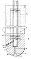
Die einzige Figur zeigt einen Längsschnitt der Tauchlanze. Die Tauchlanze 1 besteht aus einem metallenen Innenrohr 2 und einer feuerfesten keramischen monolithischen Ummantelung 3. Das untere Ende des Innenrohres 2 ist mit einer dünnen Blechscheibe 4 verschlossen, an die sich ein Austrittrohr 5 anschließt. Zwischen dem unteren Ende 6 des Austrittsrohres 5 und dem untersten Punkt 7 der Ummantelung 3 ist ein leicht ausbrechbares Kopfstück 8 aus Feuerfest-Material vorgesehen.The only figure shows a longitudinal section of the diving lance. The immersion lance 1 consists of a metal
Das Innenrohr 2 steht am unteren Ende 12 durch einen oder mehrere seitliche Kanäle 13 in der Ummantelung 3 mit der Umgebung in Verbindug. Durch diesen oder diese Kanäle 13 gelangen die ggf. mit Feststoffen beladenen Gase aus dem Innenrohr 2 bei eingetauchter Tauchlanze in die Metallschmelze. Wenn eine oder mehrere der Kanäle 13 mit Schlacke- oder Metallresten verstopft ist, wird das Kopfstück 8 ausgebrochen und die Blechscheibe 4 durchstoßen. Damit hat das Innenrohr 2 eine leicht zu schaffende weitere Ausmündung.The
Das Innenrohr 2 ist mit einem spiralförmig gewickelten Rippenband 9 umgeben, das so gewickelt ist, daß Rippenteile 10 mit gleichmäßigen Abständen 11 in Axialrichtung der Lanze gebildet sind. Die Rippenteile 10 stehen, wie die Zeichnung erkennen läßt, im rechten Winkel zur Längsachse des Innenrohres 2 und sind gewellt. Dadurch wird die wärmeableitende Oberfläche vergrößert.The
Eine Stabilitätserhöhung ergibt sich durch einen oder mehrere Stäbe 14, die am Außenumfang des Rippenbandes 9 parallel zur Achse des Innenrohrs 2, z. B. durch Schweißen oder Löten, angebracht sind. Mehrere Stäbe 14 können das Rippenband 9 käfigartig umgeben. An increase in stability results from one or
Claims (8)
dadurch gekennzeichnet, daß die das Innenrohr (2) umgebende Armierung aus mindestens einem spiralförmig gewickelten Rippenband (9) gebildet ist, das Rippenteile (10) mit gleichmäßigen Abständen (11) bildet und mit dem Innenrohr (2) verbunden ist.1. immersion lance for introducing treatment media, such as gases, in particular inert gases and / or carrier gases, with which solids, such as slag-forming substances, carbon or the like, are transported into a container filled with liquid metal, in particular for the treatment of pig iron or steel, consisting of a metal inner tube for the supply of the medium and a refractory monolithic ceramic jacket, which is held by means of a reinforcement attached to the inner tube, and one or more outlet openings penetrating the jacket,
characterized in that the reinforcement surrounding the inner tube (2) is formed from at least one spirally wound fin band (9) which forms fin parts (10) at uniform intervals (11) and is connected to the inner tube (2).
dadurch gekennzeichnet, daß die Rippenteile (10) rechtwinklig zur Längsachse des Innenrohres (2) stehen.2. diving lance according to claim 1,
characterized in that the rib parts (10) are perpendicular to the longitudinal axis of the inner tube (2).
dadurch gekennzeichnet, daß das Rippenband (9) so gewickelt ist, daß die Abstände (11) zwischen benachbarten Rippenwindungen 1/6 bis 3/6 des Innendurchmessers des Innenrohres (2) betragen.3. diving lance according to claim 1 or 2,
characterized in that the fin belt (9) is wound so that the distances (11) between adjacent fin windings are 1/6 to 3/6 of the inner diameter of the inner tube (2).
dadurch gekennzeichnet, daß sich das Rippenband (9) über nahezu die gesamte von der Ummantelung (3) abgedeckte Länge des Innenrohres (2) erstreckt.4. diving lance according to one of claims 1 to 3,
characterized in that the ribbed belt (9) extends over almost the entire length of the inner tube (2) covered by the casing (3).
dadurch gekennzeichnet, daß das untere Ende (12) des Innenrohres (2) mit einer dünnen Blechscheibe (4) verschlossen ist, an die sich ein Austrittsrohr (5) anschließt, dessen Durchmesser kleiner ist als der Durchmesser des Innenrohres (2), daß das untere Ende (6) des Austrittsrohres (5) vor dem untersten Punkt (7) der Ummantelung (3) endet und daß im untersten Bereich der Ummantelung (3) zwischen dem untersten Punkt (7) und dem unteren Ende (6) des Austrittsrohres (5) ein zentrales Kopfstück (8) aus einem einfach zu entfernenden feuerfesten Material eingesetzt ist.5. diving lance according to one of claims 1 to 4,
characterized in that the lower end (12) of the inner tube (2) is closed with a thin sheet metal disc (4) to which an outlet tube (5) connects, the diameter of which is smaller than the diameter of the inner tube (2), that the lower end (6) of the outlet pipe (5) ends before the lowest point (7) of the casing (3) and that in the lowest region of the casing (3) between the lowest point (7) and the lower end (6) of the outlet pipe ( 5) a central head piece (8) made of an easy-to-remove refractory material is used.
dadurch gekennzeichnet, daß die Rippenteile (10) gewellt sind.6. diving lance according to one of claims 1 to 5,
characterized in that the rib parts (10) are corrugated.
dadurch gekennzeichnet, daß die Rippenteile (10) durch mindestens einen sich parallel zur Achse des Innenrohrs (2) erstreckenden Stab (14) miteinander verbunden sind.7. diving lance according to one of claims 1 to 6,
characterized in that the rib parts (10) are connected to one another by at least one rod (14) extending parallel to the axis of the inner tube (2).
dad urch gekennzeichnet, daß zwei oder mehrere Stäbe (14) abstandsweise am Umfang des Rippenbandes (9) verteilt käfigartig angebracht sind.8. diving lance according to claim 7,
dad characterized in that two or more rods (14) are spaced cage-like attached to the circumference of the ribbed belt (9).
Priority Applications (1)
| Application Number | Priority Date | Filing Date | Title |
|---|---|---|---|
| AT87111378T ATE52279T1 (en) | 1986-08-20 | 1987-08-06 | DIVING LANCE. |
Applications Claiming Priority (4)
| Application Number | Priority Date | Filing Date | Title |
|---|---|---|---|
| DE8622299U | 1986-08-20 | ||
| DE19868622299 DE8622299U1 (en) | 1986-08-20 | 1986-08-20 | Diving lance |
| DE3719862 | 1987-06-13 | ||
| DE3719862A DE3719862C2 (en) | 1986-08-20 | 1987-06-13 | DIVE LANCE |
Publications (2)
| Publication Number | Publication Date |
|---|---|
| EP0261365A1 true EP0261365A1 (en) | 1988-03-30 |
| EP0261365B1 EP0261365B1 (en) | 1990-04-25 |
Family
ID=25856649
Family Applications (1)
| Application Number | Title | Priority Date | Filing Date |
|---|---|---|---|
| EP87111378A Expired - Lifetime EP0261365B1 (en) | 1986-08-20 | 1987-08-06 | Immersion lance |
Country Status (4)
| Country | Link |
|---|---|
| US (1) | US4783060A (en) |
| EP (1) | EP0261365B1 (en) |
| DE (2) | DE3719862C2 (en) |
| ES (1) | ES2015560B3 (en) |
Cited By (1)
| Publication number | Priority date | Publication date | Assignee | Title |
|---|---|---|---|---|
| EP0368266A1 (en) * | 1988-11-11 | 1990-05-16 | Linde Aktiengesellschaft | Process and cupola installation for the production of high-grade iron |
Families Citing this family (2)
| Publication number | Priority date | Publication date | Assignee | Title |
|---|---|---|---|---|
| DE29914990U1 (en) * | 1999-08-27 | 2001-01-18 | Plibrico Gmbh | Reinforcement for sheathing a metal pipe |
| AUPR624801A0 (en) * | 2001-07-10 | 2001-08-02 | Technological Resources Pty Limited | A gas injection lance |
Citations (7)
| Publication number | Priority date | Publication date | Assignee | Title |
|---|---|---|---|---|
| US3833209A (en) * | 1973-04-04 | 1974-09-03 | Berry Metal Co | Apparatus for refining of steel |
| DE7613309U1 (en) * | 1976-04-28 | 1976-09-02 | Stahlwerke Peine-Salzgitter Ag, 3150 Peine | LANCE FOR INJECTING FLUIDIZED SUBSTANCES INTO A METAL MELT |
| DE2439700B2 (en) * | 1973-08-22 | 1977-07-14 | GR Stem Refractories Ltd, Shef field, Yorkshire (Großbritannien) | LANCE FOR INJECTING FLUIDIZED SUBSTANCES INTO A METAL MELT AND PROCESS FOR THEIR PRODUCTION |
| EP0091127A1 (en) * | 1982-04-06 | 1983-10-12 | Energiagazdalkodasi Intezet | Helicoidally finned tubes |
| EP0106822A1 (en) * | 1982-10-15 | 1984-04-25 | IFM Development AB | Nozzle for injection lance |
| DE3322556A1 (en) * | 1983-06-23 | 1985-01-10 | Didier-Werke Ag, 6200 Wiesbaden | Lance for blowing fluidised materials into molten metal |
| BE904670R (en) * | 1978-10-27 | 1986-08-18 | Desaar Rene | Improved injection lance nozzle desulphurising etc. hot metal - has at least two outlet tubes arranged to ensure lateral injection |
Family Cites Families (6)
| Publication number | Priority date | Publication date | Assignee | Title |
|---|---|---|---|---|
| JPS4827045B1 (en) * | 1970-06-23 | 1973-08-18 | ||
| DE2626982C3 (en) * | 1975-01-21 | 1985-04-04 | GR-Stein Refractories Ltd., Sheffield, Yorkshire | Lance for blowing fluidized substances into a molten metal and method for producing the lance |
| BE879036A (en) * | 1979-09-27 | 1980-01-16 | Desaar Rene | SQUEEGEE FOR BLOWING OR INJECTION LANCE |
| DE8312421U1 (en) * | 1983-04-27 | 1983-09-15 | Plibrico Co GmbH, 4000 Düsseldorf | DIVE LANCE |
| SU1206314A1 (en) * | 1984-05-30 | 1986-01-23 | Научно-исследовательский институт металлургии | Tuyere for bottom blowing of metal |
| DE3511772A1 (en) * | 1985-03-30 | 1986-10-09 | Didier-Werke Ag, 6200 Wiesbaden | Blowing lance |
-
1987
- 1987-06-13 DE DE3719862A patent/DE3719862C2/en not_active Expired
- 1987-08-06 US US07/088,419 patent/US4783060A/en not_active Expired - Fee Related
- 1987-08-06 EP EP87111378A patent/EP0261365B1/en not_active Expired - Lifetime
- 1987-08-06 DE DE8787111378T patent/DE3762429D1/en not_active Expired - Fee Related
- 1987-08-06 ES ES87111378T patent/ES2015560B3/en not_active Expired - Lifetime
Patent Citations (7)
| Publication number | Priority date | Publication date | Assignee | Title |
|---|---|---|---|---|
| US3833209A (en) * | 1973-04-04 | 1974-09-03 | Berry Metal Co | Apparatus for refining of steel |
| DE2439700B2 (en) * | 1973-08-22 | 1977-07-14 | GR Stem Refractories Ltd, Shef field, Yorkshire (Großbritannien) | LANCE FOR INJECTING FLUIDIZED SUBSTANCES INTO A METAL MELT AND PROCESS FOR THEIR PRODUCTION |
| DE7613309U1 (en) * | 1976-04-28 | 1976-09-02 | Stahlwerke Peine-Salzgitter Ag, 3150 Peine | LANCE FOR INJECTING FLUIDIZED SUBSTANCES INTO A METAL MELT |
| BE904670R (en) * | 1978-10-27 | 1986-08-18 | Desaar Rene | Improved injection lance nozzle desulphurising etc. hot metal - has at least two outlet tubes arranged to ensure lateral injection |
| EP0091127A1 (en) * | 1982-04-06 | 1983-10-12 | Energiagazdalkodasi Intezet | Helicoidally finned tubes |
| EP0106822A1 (en) * | 1982-10-15 | 1984-04-25 | IFM Development AB | Nozzle for injection lance |
| DE3322556A1 (en) * | 1983-06-23 | 1985-01-10 | Didier-Werke Ag, 6200 Wiesbaden | Lance for blowing fluidised materials into molten metal |
Cited By (1)
| Publication number | Priority date | Publication date | Assignee | Title |
|---|---|---|---|---|
| EP0368266A1 (en) * | 1988-11-11 | 1990-05-16 | Linde Aktiengesellschaft | Process and cupola installation for the production of high-grade iron |
Also Published As
| Publication number | Publication date |
|---|---|
| ES2015560B3 (en) | 1990-09-01 |
| DE3719862A1 (en) | 1988-02-25 |
| DE3762429D1 (en) | 1990-05-31 |
| EP0261365B1 (en) | 1990-04-25 |
| DE3719862C2 (en) | 1988-10-27 |
| US4783060A (en) | 1988-11-08 |
Similar Documents
| Publication | Publication Date | Title |
|---|---|---|
| DE2745622C2 (en) | Vessel for a metal melting furnace, in particular an electric arc furnace | |
| DD149944A5 (en) | DEVICE FOR REFINING MELTED ALUMINUM | |
| DE3415916A1 (en) | METHOD FOR HEAT EXHAUST FROM A OR PIPE ARRANGED FOR HEATING | |
| DE2609366A1 (en) | THIN-WALLED PIPE, IN PARTICULAR AS A HOT AIR DUCT FOR PLANES | |
| EP0171583B1 (en) | Tubular reaction system for a tubular cracking furnace | |
| EP0261365B1 (en) | Immersion lance | |
| DE2112180C3 (en) | Cooled lance | |
| WO2007019917A1 (en) | Tapping channel for a metallurgical furnace | |
| DE102009059108A1 (en) | Electrode with cooling tube for a plasma cutting device | |
| DE3744715C2 (en) | ||
| WO2009153128A1 (en) | Oxygen blowing lance with protection element | |
| DE2156106B2 (en) | Liquid-filled lance for supplying reaction substances to metallurgical melts | |
| DE3390182C2 (en) | ||
| DE8622299U1 (en) | Diving lance | |
| DE3313998C2 (en) | Cooling plate for metallurgical furnaces, in particular blast furnaces and processes for their production | |
| DD269898A5 (en) | HEAT EXCHANGER | |
| DE1751085B2 (en) | MULTI-PART TUBE SHEET FOR HOT GAS COOLER | |
| DE2138924A1 (en) | Pressure vessel for preferably liquid metal-cooled atomic nuclear reactors | |
| DD202177A5 (en) | METHOD FOR LOADING A BUCKET, IN PARTICULAR A SHAFY, WITH SCHUETTGUT | |
| DE2725813A1 (en) | METALLURGICAL SHAFT FURNACE | |
| DD145181A3 (en) | REACTOR FOR GAS GENERATION BY PARTIAL OXIDATION UNDER INCREASED PRESSURE | |
| CH643300A5 (en) | Reactor pressure vessel with a heat treatment device for extending the service life of the pressure vessel | |
| EP0170142A2 (en) | Safety device for vessels for storing low-boiling liquefied gases | |
| DE2849504A1 (en) | Immersion lance for injecting gas or powder into molten metal - esp. into steel, where lance tube is reinforced by tubes carrying coolant | |
| DE3708230C2 (en) |
Legal Events
| Date | Code | Title | Description |
|---|---|---|---|
| PUAI | Public reference made under article 153(3) epc to a published international application that has entered the european phase |
Free format text: ORIGINAL CODE: 0009012 |
|
| AK | Designated contracting states |
Kind code of ref document: A1 Designated state(s): AT BE DE ES FR GB IT LU SE |
|
| 17P | Request for examination filed |
Effective date: 19880413 |
|
| 17Q | First examination report despatched |
Effective date: 19890922 |
|
| GRAA | (expected) grant |
Free format text: ORIGINAL CODE: 0009210 |
|
| AK | Designated contracting states |
Kind code of ref document: B1 Designated state(s): AT BE DE ES FR GB IT LU SE |
|
| REF | Corresponds to: |
Ref document number: 52279 Country of ref document: AT Date of ref document: 19900515 Kind code of ref document: T |
|
| ITF | It: translation for a ep patent filed |
Owner name: BARZANO' E ZANARDO ROMA S.P.A. |
|
| ET | Fr: translation filed | ||
| REF | Corresponds to: |
Ref document number: 3762429 Country of ref document: DE Date of ref document: 19900531 |
|
| GBT | Gb: translation of ep patent filed (gb section 77(6)(a)/1977) | ||
| PGFP | Annual fee paid to national office [announced via postgrant information from national office to epo] |
Ref country code: LU Payment date: 19900727 Year of fee payment: 5 |
|
| PLBE | No opposition filed within time limit |
Free format text: ORIGINAL CODE: 0009261 |
|
| STAA | Information on the status of an ep patent application or granted ep patent |
Free format text: STATUS: NO OPPOSITION FILED WITHIN TIME LIMIT |
|
| 26N | No opposition filed | ||
| PG25 | Lapsed in a contracting state [announced via postgrant information from national office to epo] |
Ref country code: DE Effective date: 19910501 |
|
| PGFP | Annual fee paid to national office [announced via postgrant information from national office to epo] |
Ref country code: GB Payment date: 19910722 Year of fee payment: 5 |
|
| PGFP | Annual fee paid to national office [announced via postgrant information from national office to epo] |
Ref country code: FR Payment date: 19910724 Year of fee payment: 5 |
|
| PGFP | Annual fee paid to national office [announced via postgrant information from national office to epo] |
Ref country code: ES Payment date: 19910801 Year of fee payment: 5 Ref country code: AT Payment date: 19910801 Year of fee payment: 5 |
|
| PGFP | Annual fee paid to national office [announced via postgrant information from national office to epo] |
Ref country code: SE Payment date: 19910802 Year of fee payment: 5 |
|
| PGFP | Annual fee paid to national office [announced via postgrant information from national office to epo] |
Ref country code: BE Payment date: 19910812 Year of fee payment: 5 |
|
| ITTA | It: last paid annual fee | ||
| EPTA | Lu: last paid annual fee | ||
| PG25 | Lapsed in a contracting state [announced via postgrant information from national office to epo] |
Ref country code: LU Free format text: LAPSE BECAUSE OF NON-PAYMENT OF DUE FEES Effective date: 19920806 Ref country code: GB Effective date: 19920806 Ref country code: AT Effective date: 19920806 |
|
| PG25 | Lapsed in a contracting state [announced via postgrant information from national office to epo] |
Ref country code: SE Effective date: 19920807 Ref country code: ES Free format text: LAPSE BECAUSE OF THE APPLICANT RENOUNCES Effective date: 19920807 |
|
| PG25 | Lapsed in a contracting state [announced via postgrant information from national office to epo] |
Ref country code: BE Effective date: 19920831 |
|
| BERE | Be: lapsed |
Owner name: PLIBRICO CY G.M.B.H. Effective date: 19920831 |
|
| GBPC | Gb: european patent ceased through non-payment of renewal fee |
Effective date: 19920806 |
|
| PG25 | Lapsed in a contracting state [announced via postgrant information from national office to epo] |
Ref country code: FR Effective date: 19930430 |
|
| REG | Reference to a national code |
Ref country code: FR Ref legal event code: ST |
|
| EUG | Se: european patent has lapsed |
Ref document number: 87111378.3 Effective date: 19930307 |
|
| REG | Reference to a national code |
Ref country code: ES Ref legal event code: FD2A Effective date: 19991007 |
|
| PG25 | Lapsed in a contracting state [announced via postgrant information from national office to epo] |
Ref country code: IT Free format text: LAPSE BECAUSE OF NON-PAYMENT OF DUE FEES Effective date: 20050806 |