EP0261119B1 - Verfahren und vorrichtung zum schneiden mit sprengstoffen - Google Patents
Verfahren und vorrichtung zum schneiden mit sprengstoffen Download PDFInfo
- Publication number
- EP0261119B1 EP0261119B1 EP86903480A EP86903480A EP0261119B1 EP 0261119 B1 EP0261119 B1 EP 0261119B1 EP 86903480 A EP86903480 A EP 86903480A EP 86903480 A EP86903480 A EP 86903480A EP 0261119 B1 EP0261119 B1 EP 0261119B1
- Authority
- EP
- European Patent Office
- Prior art keywords
- shock wave
- explosive
- cut
- target
- delay element
- Prior art date
- Legal status (The legal status is an assumption and is not a legal conclusion. Google has not performed a legal analysis and makes no representation as to the accuracy of the status listed.)
- Expired
Links
- 239000002360 explosive Substances 0.000 title claims abstract description 111
- 230000035939 shock Effects 0.000 claims abstract description 115
- 239000000463 material Substances 0.000 claims abstract description 80
- 238000005474 detonation Methods 0.000 claims abstract description 28
- 238000000034 method Methods 0.000 claims abstract description 21
- 229910052751 metal Inorganic materials 0.000 claims description 20
- 239000002184 metal Substances 0.000 claims description 20
- 230000005540 biological transmission Effects 0.000 claims description 10
- 230000000977 initiatory effect Effects 0.000 claims description 10
- 238000007493 shaping process Methods 0.000 claims description 4
- 239000011800 void material Substances 0.000 claims description 4
- 208000010392 Bone Fractures Diseases 0.000 description 7
- 206010017076 Fracture Diseases 0.000 description 7
- 239000004033 plastic Substances 0.000 description 6
- 229920003023 plastic Polymers 0.000 description 6
- CWYNVVGOOAEACU-UHFFFAOYSA-N Fe2+ Chemical compound [Fe+2] CWYNVVGOOAEACU-UHFFFAOYSA-N 0.000 description 5
- 230000004888 barrier function Effects 0.000 description 4
- 239000002245 particle Substances 0.000 description 4
- 229910001209 Low-carbon steel Inorganic materials 0.000 description 3
- 229920001971 elastomer Polymers 0.000 description 3
- 239000005060 rubber Substances 0.000 description 3
- 229920003051 synthetic elastomer Polymers 0.000 description 3
- 239000005061 synthetic rubber Substances 0.000 description 3
- 229910000831 Steel Inorganic materials 0.000 description 2
- 239000000853 adhesive Substances 0.000 description 2
- 230000001070 adhesive effect Effects 0.000 description 2
- 239000002131 composite material Substances 0.000 description 2
- 230000003111 delayed effect Effects 0.000 description 2
- 239000012634 fragment Substances 0.000 description 2
- 230000004048 modification Effects 0.000 description 2
- 238000012986 modification Methods 0.000 description 2
- AJCDFVKYMIUXCR-UHFFFAOYSA-N oxobarium;oxo(oxoferriooxy)iron Chemical compound [Ba]=O.O=[Fe]O[Fe]=O.O=[Fe]O[Fe]=O.O=[Fe]O[Fe]=O.O=[Fe]O[Fe]=O.O=[Fe]O[Fe]=O.O=[Fe]O[Fe]=O AJCDFVKYMIUXCR-UHFFFAOYSA-N 0.000 description 2
- 239000011505 plaster Substances 0.000 description 2
- 239000010959 steel Substances 0.000 description 2
- XLYOFNOQVPJJNP-UHFFFAOYSA-N water Substances O XLYOFNOQVPJJNP-UHFFFAOYSA-N 0.000 description 2
- XEEYBQQBJWHFJM-UHFFFAOYSA-N Iron Chemical group [Fe] XEEYBQQBJWHFJM-UHFFFAOYSA-N 0.000 description 1
- 208000006670 Multiple fractures Diseases 0.000 description 1
- 238000003491 array Methods 0.000 description 1
- 230000000903 blocking effect Effects 0.000 description 1
- 230000006835 compression Effects 0.000 description 1
- 238000007906 compression Methods 0.000 description 1
- 230000000694 effects Effects 0.000 description 1
- 238000001125 extrusion Methods 0.000 description 1
- 238000010304 firing Methods 0.000 description 1
- 239000000696 magnetic material Substances 0.000 description 1
- 239000011159 matrix material Substances 0.000 description 1
- 239000003129 oil well Substances 0.000 description 1
- 230000002028 premature Effects 0.000 description 1
- 230000002250 progressing effect Effects 0.000 description 1
- 230000000284 resting effect Effects 0.000 description 1
- 239000007787 solid Substances 0.000 description 1
- 239000013077 target material Substances 0.000 description 1
Images


Classifications
-
- F—MECHANICAL ENGINEERING; LIGHTING; HEATING; WEAPONS; BLASTING
- F42—AMMUNITION; BLASTING
- F42B—EXPLOSIVE CHARGES, e.g. FOR BLASTING, FIREWORKS, AMMUNITION
- F42B1/00—Explosive charges characterised by form or shape but not dependent on shape of container
-
- B—PERFORMING OPERATIONS; TRANSPORTING
- B26—HAND CUTTING TOOLS; CUTTING; SEVERING
- B26F—PERFORATING; PUNCHING; CUTTING-OUT; STAMPING-OUT; SEVERING BY MEANS OTHER THAN CUTTING
- B26F3/00—Severing by means other than cutting; Apparatus therefor
- B26F3/04—Severing by squeezing
Definitions
- This invention relates to explosive cutting means.
- One well known method for explosive cutting is the so called "plaster” charge method and wherein a strip of explosive material is applied directly to the target along the intended line of cut and is detonated to generate fracture forces within the target along the intended line of cut.
- Another well known method for explosive cutting is the so called "shaped charge" method and wherein a metal element, initially spaced from the target, is driven at high speed against the target along the intended line of cut by detonation of an explosive material.
- the metal element is deformed by the detonation and by passage through the air to the target and a blade-like high speed jet of metal strikes the target to cut the target.
- a target be cut along an intended line by producing two shock wave fronts in the target, the two shock wave fronts first entering the surface of the target simultaneously along two zones extending parallel to the intended line of cut and spaced apart with the intended line of cut mid-way between them.
- the two shock wave fronts pass into the target and meet along the intended line of cut and the shock waves reflected from the undersurface of the target also coincide along the intended line of cut.
- two-wave explosive cutting For convenience the above described method of cutting by producing two spaced apart wave fronts simultaneously in the surface of the target shall be referred to as “two-wave explosive cutting” and means for producing two-wave explosive cutting shall hereinafter be referred to as “two-wave explosive cutting means”.
- United States Patent No. 3,076,408 discloses two-wave explosive cutting means in which a layer of explosive material is arranged in contact with the surface of a target to be cut and extends across the intended line of cut. The explosive material is detonated simultaneously at points on either side of the intended line of cut to produce the two-wave explosive cutting. This document is the basis of the preamble of claim 1.
- United States Patent No. 3,435,763 discloses the two-wave explosive cutting means wherein an explosive strip is adapted to be arranged in contact with a surface of a target on either side of an intended line of cut and said strip comprises means for so controlling detonation of the material that a pair of converging re-entrant detonation fronts proceed simultaneously and symmetrically inwards to generate a Mach stem internally of the strip.
- a detonation front is a front which travels through an explosive mass, from the point of initiation of the detonation, to continue the detonation of the explosive mass and therefore a detonation front can exist only within an explosive mass.
- a shock wave front is generated by a detonation front at a surface or surfaces of a detonating mass and thus exists only outwardly of the explosive mass.
- the speed at which the detonation front(s) pass through the explosive material is very high as also is the speed at which the shock wave fronts pass through the target.
- the cut in the target is effected along the plane in which the two shock wave fronts meet any minute variation in the time of entry of the shock waves into the target, or any difference in the "balance" of the shock wave configurations, will cause the cut to deviate from the intended line of cut.
- any system which relies on detonating the explosive material at a plurality of locations must be suspect in that any premature or delayed firing of any one of the detonators will result in an undesired detonation configuration with deviation from the intended line of cut.
- Any system which relies on barriers to periodically re-establish side edge detonation and wherein the detonation effectively proceeds independantly along the side edges of the explosive material must also be suspect. It is for this reason that prior art two-wave cutting is rarely used on long cuts, such as cuts in excess of 1 ⁇ 2 metre.
- the object of the present invention is to provide a method and means for two-wave explosive cutting which does not rely on controlling the configuration of the detonation front through the explosive charge.
- a method for two-wave explosive cutting of a target along an intended line of cut comprising the steps of locating an explosive material to extend along the intended line of cut and on both sides of the intended line of cut and detonating said explosive material, characterised by the steps of supporting the mid-regions of the explosive material, in planes at right angles to the intended line of cut, on a shock wave delay element, shaping the explosive material to have a substantially uniform cross-section in planes at right angles to the direction of the intended line of cut with the explosive material at the side edges in each said cross-section closer to the target surface than the shock-wave delay element-supported mid-regions thereof, and detonating said explosive material to generate a detonation front in said explosive material travelling in the direction of the intended line of cut.
- the method is characterised by the steps of shaping the cross-section of the shock wave delay element in planes at right angles to the intended line of cut to control the progression of the shock waves through said shock wave delay element to the target surface.
- the method comprises the steps of constructing the shock wave delay element of different shock wave transmission materials to control the progress of the shock waves through the shock wave delay element to the target surface.
- the method comprises the steps of locating a metal element between the target and the explosive material, said metal element extending along the length of the intended line of cut and being spaced from the target surface, and providing a void in the shock wave delay element between said metal insert and the target surface.
- the method comprises the steps of forming a void, extending in the direction of the intended line of cut, in the shock wave delay element to further delay the progression of the mid-regions of the shock wave front, in planes at right angles to the intended direction of cut, through the shock wave delay element to the target surface.
- the invention also envisages a two wave-explosive cutting means comprising an elongate shock wave delay element of substantially uniform cross-section, intended to extend in the length direction of an intended line of cut, and an explosive material having its mid-regions, in planes at right angles to the intended line of cut, supported on said element.
- said cutting means has its said shock wave delay element presenting a target-engaging surface and an explosive-supporting surface or surfaces facing away from said target-engaging surface, said surfaces extending in the length direction of said element.
- the said shock wave delay element includes areas of different shock wave transmission characteristics in each cross-section of said element at right angles to the longitudinal direction of said element.
- the shock wave delay element has a greater thickness at its mid-regions than at its side edges in planes at right angles to the longitudinal direction of the said element.
- shock wave delay element is of generally triangular cross-section in planes at right angles to the longitudinal direction of the element, one major face of the element defines the target-engaging surface of the element and the other two major faces of the element define explosive-supporting surfaces of the element.
- the cross-section of the shock wave delay element is generally in the form of an isosceles triangle, with a high base to height ratio, and the base surface of said triangle comprises the target-engaging surface.
- the said shock wave delay element includes a recess in said target-engaging surface extending along the length direction of the element and intended to straddle the intended line of cut of a target.
- a metal insert is located in said recess to extend in the length direction of the shock wave delay element and said insert is spaced from the target-engaging face of the delay element and is intended to straddle the intended line of cut.
- the shock wave delay element is curved, in its longitudinal direction, and its two ends are joined to form a closed loop tightly embrace the target surface.
- the shock wave delay element includes a magnetized element or elements.
- the present invention also envisages a two-wave cutting means as defined above in combination with an initiation means.
- the initiation means include a detonator and a sheet of explosive material located to detonate the explosive material on the shock wave delay element when the detonator is fired, said sheet of explosive material when detonated being arranged to detonate the explosive material on the shock wave delay element over a substantially straight detonation front at right angles to the length direction of the shock wave delay element.
- the element 11 has the mid-plane CL passing through its transverse cross section in the plane of the intended line of cut 14, in the target so that, in its width direction, the element 11 extends equally on either side of the line of cut 14.
- the element 11 comprises, in cross section, an isosceles triangle 11 a of a first material and two equal right-angle triangles 11 b 11 c of a second material, the first and second materials being selected to have different shock-wave transmission characteristics with the triangle 11 a having the slowest transmission characteristics.
- Figs 1A, 1B and 1C show cross sections of the element 11 to the left of the mid-plane CL and it will be appreciated that the shock wave fronts described with respect to Figs 1A 1B and 1C are mirror images of the shock wave fronts as will be developed in the cross section of the element 11 to the right of the plane CL.
- the shock wave front 15 a travelling wholly through the triangle 11 b will have travelled a distance D and will be progressing parallel to the surface 11.
- the shock wave front 15 b which has passed through the plane joining triangle 11 a to triangle 11 b will have travelled part way through triangle 11 b and part way through 11 a and will therefore be inclined to the plane of surface 12 a .
- Fig 1B shows the position when the shock wave has travelled to the lower-most point of triangle 11 b and one half the height of triangle 11 a at the mid-plane CL and it will be noted that the shock wave has a releatively straight front 15.
- Fig 1C shows the position wherein the shock wave front 15 has passed wholly into the target 12 and the inclined part 15 c of said front is travelling towards the line of cut 14.
- Figs 1A, 1B and 1C are mirror images of the sections and progression of the shock wave fronts on the right hand side of the mid-plane CL and, when the explosive material 13 is detonated on a straight front travelling in the length direction of element 11, shock wave fronts will first enter the surface 12 a of target 12 from the lowest points of triangles 11 b and 11 c , as viewed in Fig 1, simultaneously and the inclined shock wave fronts 15 c will meet at the intended line of cut 14.
- a shock wave delay element 21 of elongate form has a transverse cross-section in the form of an isosceles triangle with a high base to height ratio and the surface 21 a , defined by the base, comprises the target-engaging surface of the element 21.
- the remaining major surfaces 21 b and 21 c of the element 21 comprise the explosive-supporting surfaces.
- the element 21 is placed on a target 22 with its length direction extending in the direction of the intended line of cut 23 and its target-engaging surface 21 a in contact with the surface 22 a of the target.
- the target-engaging surface 21 a extends equally on either side of the intended line of cut 23.
- the shock wave front 25 generated by the explosive material 24 travels through the shock wave delay element 11 to the surface 22 a of target 22. Entry of the shock wave 25 into the target 22 is first at zones 22 b , 22 c where the explosive material 24 is closest to the target 22 and has the minimum delay in travelling through the element 21 and, as the height of the element 21 increases towards the plane of the intended cut 23, so the shock wave front 25 is delayed in its passage to the target 22 by the increasing thickness of element 21.
- the shock wave front 25 first enters the target 22 at the two zones or regions 22 b , 22 c , which are equally spaced apart from the intended plane of cut 23, and the inclined shock wave fronts 25 a and 25 b passing through the element 21 parallel to surfaces 21 b , 21 c respectively travel towards one another to coincide at the plane of the intended cut 23.
- Fig 2 the shock wave fronts 25 are shown passing into a target 22 having substantially the same shock-wave transmission characteristics as the element 21.
- Fig 3 shows a view similar to Fig 2, and using identical reference numerals for identical parts, the essential difference from Fig 2 being that the shock wave transmission speed for the element 21 is slower than for the target material whereby the angles of the inclined shock wave fronts 25 a and 25 b within the target 22 are steeper (as viewed in Fig 3) than the angle of the shock wave fronts 25 a , 25 b within the target 22 shown in Fig 2.
- the shock wave delay element 11 of Fig 1 and the shock wave delay elements 21 of Figs 2 and 3 may be constructed from any suitable materials having the desired shock wave transmission speeds but preferably said element 11 of Fig 1 and the elements 21 of Figs 2 and 3 are constructed from rubber, synthetic rubber or plastics materials, and have sufficient flexibility to allow the respective shock wave delay elements 11 or 21 to follow non-linear contours, such as the curved surfaces of pipes and tubes.
- the elements 11 and 21 may also include a soft iron core element 26 (illustrated only in Fig 2) on the mid-plane CL and extending in the length direction of the respective delay element and which can assist in holding the shock wave element in a shape imparted to follow a non-linear contour.
- a soft iron core element 26 illustrated only in Fig 2 on the mid-plane CL and extending in the length direction of the respective delay element and which can assist in holding the shock wave element in a shape imparted to follow a non-linear contour.
- the elements 11 and 21 may also include magnetized material, such as magnetized particles of barium ferrite, so that the respective element 11 or 21 can magnetically adhere to the surface of a ferrous target.
- the explosive material 13 of Fig 1 and 24 of Figs 2 and 3 may be secured to its respective element 11 or 22 with an adhesive material, preferably not a water-soluble adhesive.
- Fig 4 illustrate a modification which can be applied to the embodiments illustrated in Figs 2 and 3.
- a strip of ferrous metal 27 is bonded to the base surface of the element 21 and a strip of magnetized material 28, such as a rubber or plastics material including magnetized particles, is bonded to the metal 27 so that the composite element 11 can adhere to ferrous targets without the inclusion of magnetized particles within the element 21.
- Fig 5 it will be seen that the embodiment illustrated therein is similar to the embodiments of Fig 2 and 3, like numerals again identify like parts, with the exception that the apex of the shock wave delay element 21 is truncated and the element 21 has a central triangular cavity 30 therein the apex of which is lower-most (as viewed in Fig 5) and coincides with the intended line of cut 23 and the base of which is covered by a plate 31, e.g., of metal. The plate 31 is covered by the explosive material 24.
- the plate 31 When the strip of explosive material 24 is detonated the plate 31 will be driven downwardly and, guided by the side walls of the cavity 30, will form a high velocity metal jet directed towards the intended line of cut 23. This jet will not cut the target 22 but will indent or recess the surface of the target 22 along the intended line of cut 23 to assist fracture of the target along said intended line of cut 23.
- the shock wave delay element 21 is provided with a triangular cavity 32 which extends the length thereof and which has its base astride the intended line of cut.
- the cavity 32 may be metal lined if desired. It has been found in practice that the cavity 32 greatly assists focusing of the shock wave.
- the shock wave delay elements 21 of Figs 5 and 6 may, in like manner to the embodiments described with reference to Figs 2 and 3 be made of rubber, synthetic rubber or plastics material so as to be flexible and said elements may include magnetized particles to enable the elements 21 of Figs 5 and 6 to adhere to ferrous targets.
- the plate 31 of Fig 5 may also be magnetized to assist adhesion of the insert 23 to a ferrous target.
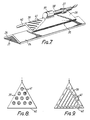
- Fig 7 shows initiating means 35 suitable for use with the explosive cutting means of any of the embodiments illustrated in Figs 2 to 6 inclusive.
- the initiating means 35 comprise a support 36 of inert material shaped to conform to the shape of the exposed main faces of the explosive material 24 and which is adapted to be mounted thereon.
- the support 36 carries means 37 for supporting a detonator 38.
- the support 36 also carries on part of its surface remote from the explosive material 24, a layer of explosive material 39 which will be detonated when the detonator 38 is fired.
- the layer of explosive material 39 extends over one end of the support 36, as shown at 40, so as to contact the explosive material 24 when the initiating means is properly located on the explosive cutting means.
- the layer of explosive material 39 is substantially triangular in plan view and has incorporated therein barrier elements 41 which are so arranged that all paths from the detonator 38 to each point along the edge 40 are of substantially the same length to ensure that detonation of the explosive material 24 takes place substantially simultaneously at all points across the width thereof.
- Fig 8 illustrates an array of circular barrier elements 41, for the explosive layer 39 whilst Fig 9 illustrates an array of linear barrier elements 41, both of these arrays being such as to achieve the desired object of ensuring that all paths between the point of detonation of the layer of explosive material 39 and and the edge 40 which initiates the explosive material 24 are of substantially the same length.
- the shock wave delay element focuses the shock wave generated by detonation of the explosive material to produce entry of the shock wave into the target first at two zones or locations equally spaced on either side of the intended line of cut whereby the classic "two-wave” cutting is achieved when the shock waves progress from said two zones to coincide at the intended line of cut.
- explosive cutting means according to the present invention can be used in a side-by-side array or, alternatively, an explosive cutting means may be formed which comprises, in effect, a plurality of cutting means according to the present invention arranged side-by-side.
- two-shock wave cutting means as shown in Fig 2, 3, 4, 5 or 6 could be assembled in side-by-side relationship on a common sheet to form a series of side-by-side corrugations extending across the width of a sheet, with each corrugation providing a separate two-wave explosive cutting means according to the present invention but with corrugations sharing a common sheet of explosive metal.
- the facility for providing multiple fractures or cuts is particularly useful when removing a section of lining from a bore or well, e.g., an oil well, since it enables the section of lining to be cut into sufficiently small pieces for either easy removal or for falling with little danger of blocking of the bore or well to the bottom of the bore or well.
- the elements 11, 21 have been described as elongate but it will be appreciated that when said elements are flexible the two-wave cutting means can be deflected to cut a target along lines other than straight lines.
- the elongate shock wave delay elements described above may be easily made by conventional extrusion processes and the explosive material 24 may also be extruded to the desired cross section. Thus, the assembly of the cpmponent parts of the shock wave cutting means is simplified.
- shock wave delay elements required for cuts which cannot be made by flexing an elongate cutting means may be moulded to follow virtually any desired cut configuration.
- the elements may be moulded in "closed" configuration, such as a circular configuration to cut a disc from a target.
- shapes for a cut can be built up using elongate and curved delay elements to cut, for example,a rectangular hole with curved corners.
- the two-wave cutting means illustrated in Figs 1 to 6 inclusive may be of conical configuration, defining solids of revolution about the mid-plane (axis) CL, whereupon the shock waves will coincide at a core region passing through the target.
- a shock wave delay element of the kind shown in Fig 2 was constructed from a composite magnetic material comprising 92.5% barium ferrite in a matrix of synthetic rubber which is sold under the registered trade mark FEROBA. This element had a density of 3.6g/cc.
- the cross-section of the element was an isosceles triangle having a base of 30mm and an apex of 130 o .
- the base of the element was magnetically adhered to a plate of mild steel 7.9mm thick.
- To the remaining two sides of the element was applied a single strip of RDX-based plastic explosive of the kind designated SX2. This strip was 32mm wide and 3mm thick.
- the strip of explosive material was initiated at a point on the longitudinal axis thereof, at a distance of 40mm from the start of the intended line of cut so that the detonation front would have time to develop prior to the start of the intended line of cut.
- the plate was divided by a continuous and very straight fracture.
- a shock wave delay element of the kind used in Example 1 was magnetically adhered by its base to a mild steel plate 15.3mm thick. To the other two sides of the element was applied two strips of SX2 plastic explosive, the strips each being 32mm wide and 3mm thick and being applied one upon the other to give a double thickness.
- the plate was fractured along a continuous and very straight edged line. A thick spall was projected from the rear of the plate and this spall was itself divided neatly along the line of intended cut.
- a particular feature of this Example was that the spall fragments exhibited straight and square outer edges. Normally, when a strip of explosive material is detonated in contact with a metal plate so as to cause a spall to be projected from the opposite side thereof, the edges of the spall fragments are ragged and somewhat tapered.
- Two strips of SX2 plastic explosive 32mm wide and 3mm thick were folded along their longitudinal centre line so that the two sides extended at an angle of 120 o to one another.
- the two strips were positioned one upon the other on a plate of mild steel 12,5mm thick with two longitudinal side edges of the inner strip resting upon the plate.
- the assembly was immersed in water so that the water filled cavity between the inner strip of explosive material and the plate to provide a shock wave delay element.
- the explosive was initiated centrally of one end thereof.
- the steel plate was divided by a fracture which coincided with the longitudinal axis of the strips of explosive material. A narrow spall approximately 11mm wide and 5mm thick was detached from the surface of the steel plate opposite to which the explosive was applied.
- the plate was not deformed to any visible extent beyond the fracture on that surface to which the explosive material was applied and beyond the spall on the other side.
- the zone of visible damage did not extend laterally beyond about 5.5mm from the centre line of the fracture. This is a much narrower damage zone than usually occurs with known fracturing or cutting charges of comparable severing power.
Landscapes
- Engineering & Computer Science (AREA)
- General Engineering & Computer Science (AREA)
- Life Sciences & Earth Sciences (AREA)
- Forests & Forestry (AREA)
- Mechanical Engineering (AREA)
- Perforating, Stamping-Out Or Severing By Means Other Than Cutting (AREA)
- Pressure Welding/Diffusion-Bonding (AREA)
- Disintegrating Or Milling (AREA)
Claims (17)
- Verfahren zum Zweiwellen-Explosionsschneiden eines Gegenstands entlang einer gewünschten Trennlinie, umfassend die folgenden Schritte: Anordnen eines Sprengstoffes, so daß er entlang der gewünschten Trennlinie und zu beiden Seiten der Trennlinie verläuft, und Detonieren dieses Sprengstoffes, gekennzeichnet durch die folgenden Schritte:
Haltern der Mittenbereiche des Sprengstoffs (13, 24) in rechtwinklig zu der gewünschten Trennlinie verlaufenden Ebenen auf einem Stoßwellenverzögerungselement (11, 21), Formen des Sprengstoffs (13, 24) derart, daß sein Querschnitt in rechtwinklig zu der Richtung der gewünschten Trennlinie (14, 23) verlaufenden Ebenen im wesentlichen gleichförmig ist, wobei der Sprengstoff (13, 24) an den Seitenrändern in jedem Querschnitt näher an der Oberfläche (12a, 22a) des Gegenstands liegt als seine von dem Stoßwellenverzögerungselement (11, 21) gehalterten Mittenbereiche, und
Detonieren des Sprengstoffs (13, 24) zur Erzeugung einer Detonationsfront in dem Sprengstoff (13, 24), die sich in Richtung der gewünschten Trennlinie (14, 23) fortbewegt. - Verfahren nach Anspruch 1,
gekennzeichnet durch den Schritt der Formung des Querschnitts des Stoßwellenverzögerungselements (11, 21) in rechtwinklig zu der gewünschten Trennlinie (14, 23) verlaufenden Ebenen, um die Ausbreitung der Stoßwellen (15a, 15b, 25a, 25b) durch das Stoßwellenverzögerungselement (11, 21) zur Oberfläche (12a, 22a) des Gegenstands zu kontrollieren. - Verfahren nach Anspruch 1 oder 2,
gekennzeichnet durch den Schritt des Aufbaus des Stoßwellenverzögerungselements (11) aus verschiedenen Stoßwellendurchlaßmaterialien (11a, 11b, 11c), um die Ausbreitung der Stoßwellen durch das Stoßwellenverzögerungselement (11) zur Oberfläche (12a) des Gegenstands zu kontrollieren. - Verfahren nach einem der vorhergehenden Ansprüche,
gekennzeichnet durch die folgenden Schritte: Anordnen eines Metallteiles (31) zwischen dem Gegenstand (11, 21) und dem Sprengstoff (13, 24), wobei sich das Metallteil (31) entlang der Länge der gewünschten Trennlinie (14, 23) erstreckt und von der Oberfläche (12a, 22a) des Gegenstands beabstandet ist, und Vorsehen eines Hohlraumes (30) in dem Stoßwellenverzögerungselement (11, 21) zwischen dem Metallteil (31) und der Oberfläche (12a, 22a) des Gegenstands. - Verfahren nach einem der vorhergehenden Ansprüche,
gekennzeichnet durch den Schritt der Formung eines Hohlraumes (30) in dem Stoßwellenverzögerungselement (11, 21), der in Richtung der gewünschten Trennlinie (14, 23) verläuft, um die Ausbreitung der Mittenbereiche der Stoßwellenfront in rechtwinklig zu der gewünschten Trennrichtung (14, 23) verlaufenden Ebenen durch das Stoßwellenverzögerungselement (11, 21) zur Oberfläche (12a, 22a) des Gegenstands weiter zu verzögern. - Zweiwellen-Explosionsschneidvorrichtung,
umfassend ein langgestrecktes Stoßwellenverzögerungselement (11, 21) mit im wesentlichen gleichförmigem Querschnitt, das sich in Längsrichtung einer gewünschten Trennlinie erstreckt, und einen Sprengstoff (13, 24), dessen Mittenbereiche in rechtwinklig zu der gewünschten Trennlinie verlaufenden Ebenen auf dem Stoßwellenverzögerungselement (11, 21) abgestützt sind. - Zweiwellen-Explosionsschneidvorrichtung nach Anspruch 6,
dadurch gekennzeichnet, daß das Stoßwellenverzögerungselement (11, 21) eine Gegenstands-Anlagefläche (21a) und eine Sprengstofftragfläche oder -flächen (21b, 21c) aufweist, die von der Gegenstands-Anlagefläche (21a) weg gerichtet sind, wobei diese Flächen (21a, 21b und 21c) in Längsrichtung des Stoßwellenverzögerungselements (11, 21) verlaufen. - Zweiwellen-Explosionsschneidvorrichtung nach Anspruch 6 oder 7,
dadurch gekennzeichnet, daß das Stoßwellenverzögerungselement (11) Bereiche (11a, 11b, 11c) mit unterschiedlichen Stoßwellendurchlaßcharakteristiken in jedem Querschnitt des Stoßwellenverzögerungselements (11) unter rechten Winkeln zu der Längsrichtung des Elementes (11) aufweist. - Zweiwellen-Explosionsschneidvorrichtung nach einem der Ansprüche 6, 7 oder 8,
dadurch gekennzeichnet, daß das Stoßwellenverzögerungselement (21) in unter rechten Winkeln zu seiner Längsrichtung verlaufenden Ebenen, in seinen Mittenbereichen dicker als an seinen Seitenrändern ist. - Zweiwellen-Explosionsschneidvorrichtung nach einem der Ansprüche 7, 8 oder 9,
dadurch gekennzeichnet, daß das Stoßwellenverzögerungselement (21) in rechtwinklig zu seiner Längsrichtung verlaufenden Ebenen im allgemeinen Dreiecksquerschnitt hat und daß eine Hauptfläche (21a) des Stoßwellenverzögerungselements (21) seine Gegenstands-Anlagefläche bildet und die beiden anderen Hauptflächen (21b, 21c) des Elementes (21) Sprengstofftragflächen des Stoßwellenverzögerungselements (21) bilden. - Zweiwellen-Explosionsschneidvorrichtung nach Anspruch 10, wobei der Dreiecksquerschnitt des Stoßwellenverzögerungselements (21) im allgemeinen die Form eines gleichschenkligen Dreiecks mit einem großen Verhältnis von Grundlinie zu Höhe hat und daß die Grundfläche des Dreiecks die Gegenstands-Anlagefläche (21a) aufweist.
- Zweiwellen-Explosionsschneidvorrichtung nach einem der Ansprüche 6, 7, 8, 9, 10 oder 11,
dadurch gekennzeichnet, daß das Stoßwellenverzögerungselement (11, 21) in der Gegenstands-Anlagefläche (21a) eine Ausnehmung (30 oder 32) hat, die entlang der Längsrichtung des Stoßwellenverzögerungselements (11, 21) verläuft und die gewünschte Trennlinie (14, 23) eines Gegenstands übergreifen soll. - Zweiwellen-Explosionsschneidvorrichtung nach Anspruch 12, dadurch gekennzeichnet, daß in der Ausnehmung (30) ein Metalleinsatz (31) so angeordnet ist, daß er in Längsrichtung des Stoßwellenverzögerungselements (11, 21) verläuft, und daß der Einsatz (31) von der Gegenstands-Anlagefläche des Stoßwellenverzögerungselements (11, 21) beabstandet ist und die gewünschte Trennlinie (14, 23) übergreifen soll.
- Zweiwellen-Explosionsschneidvorrichtung nach einem der Ansprüche 6 bis 13 einschließlich, bei der das Stoßwellenverzögerungselement (11, 21) in seiner Längsrichtung gebogen ist und seine beiden Enden zur Bildung einer geschlossenen Schleife verbunden sind.
- Zweiwellen-Explosionsschneidvorrichtung nach einem der Ansprüche 6 bis 14 einschließlich,
dadurch gekennzeichnet, daß das Stoßwellenverzögerungselement ein magnetisiertes Element (28) oder magnetisierte Elemente enthält. - Zweiwellen-Explosionsschneidvorrichtung nach einem der Ansprüche 6 bis 15, in Kombination mit einer Zündeinrichtung (35-41).
- Zweiwellen-Explosionsschneidvorrichtung nach Anspruch 16, dadurch gekennzeichnet, daß die Zündeinrichtung einen Detonator (38) und einen Sprengstoff-Flächenkörper (40) aufweist, der so positioniert ist, daß er den Sprengstoff auf dem Stoßwellenverzögerungselement (11, 21) zur Detonation bringt, wenn der Detonator gezündet wird, wobei der Sprengstoff-Flächenkörper (40) bei der Detonation so angeordnet ist, daß er den Sprengstoff (13, 24) auf dem Stoßwellenverzögerungselement (11, 21) über eine im wesentlichen geradlinige Detonationsfront rechtwinklig zur Längsrichtung des Stoßwellenverzögerungselementes (11, 21) detoniert.
Priority Applications (1)
| Application Number | Priority Date | Filing Date | Title |
|---|---|---|---|
| AT86903480T ATE69760T1 (de) | 1985-05-28 | 1986-05-27 | Verfahren und vorrichtung zum schneiden mit sprengstoffen. |
Applications Claiming Priority (2)
| Application Number | Priority Date | Filing Date | Title |
|---|---|---|---|
| GB8513325 | 1985-05-28 | ||
| GB8513325 | 1985-05-28 |
Publications (2)
| Publication Number | Publication Date |
|---|---|
| EP0261119A1 EP0261119A1 (de) | 1988-03-30 |
| EP0261119B1 true EP0261119B1 (de) | 1991-11-27 |
Family
ID=10579714
Family Applications (1)
| Application Number | Title | Priority Date | Filing Date |
|---|---|---|---|
| EP86903480A Expired EP0261119B1 (de) | 1985-05-28 | 1986-05-27 | Verfahren und vorrichtung zum schneiden mit sprengstoffen |
Country Status (7)
| Country | Link |
|---|---|
| EP (1) | EP0261119B1 (de) |
| JP (1) | JP2514943B2 (de) |
| AT (1) | ATE69760T1 (de) |
| AU (1) | AU5908886A (de) |
| CA (1) | CA1319353C (de) |
| DE (1) | DE3682681D1 (de) |
| WO (1) | WO1986007000A1 (de) |
Families Citing this family (8)
| Publication number | Priority date | Publication date | Assignee | Title |
|---|---|---|---|---|
| GB8807044D0 (en) * | 1988-03-24 | 1988-04-27 | Univ Manchester | Explosive cutting device with waveguide |
| GB9023730D0 (en) * | 1990-11-01 | 1990-12-12 | Everest John R | Explosive lines |
| EP2434251A1 (de) | 2010-09-22 | 2012-03-28 | Nederlandse Organisatie voor toegepast -natuurwetenschappelijk onderzoek TNO | Sprengschneiden |
| RU2557298C1 (ru) * | 2013-12-26 | 2015-07-20 | Федеральное государственное казенное учреждение "12 Центральный научно-иследовательский институт" Министерство обороны Российской Федерации | Ленточный заряд из листового взрывчатого вещества |
| US10036616B2 (en) * | 2016-02-23 | 2018-07-31 | Lawrence Livermore National Security, Llc | Architected materials and structures to control shock output characteristics |
| CN109760144B (zh) * | 2019-01-31 | 2023-07-04 | 东莞市九思自动化科技有限公司 | 一种折板机构及具有该折板机构的自动化分板机 |
| US10969205B2 (en) * | 2019-05-03 | 2021-04-06 | Palo Alto Research Center Incorporated | Electrically-activated pressure vessels for fracturing frangible structures |
| CN114558930A (zh) * | 2022-04-11 | 2022-05-31 | 安徽理工大学 | 一种可变炸高的聚能切割装置 |
Family Cites Families (5)
| Publication number | Priority date | Publication date | Assignee | Title |
|---|---|---|---|---|
| US3076408A (en) * | 1958-06-11 | 1963-02-05 | Borg Warner | Controlled fracturing of solids by explosives |
| FR1215794A (fr) * | 1958-11-18 | 1960-04-20 | Algerienne D Explosifs Et D Ac | Charges explosives à front d'ondes dirigé |
| US3435763A (en) * | 1967-06-20 | 1969-04-01 | Arthur A Lavine | Explosive arrangement for generating a mach stem to affect a line cut |
| DE2832246C2 (de) * | 1978-07-22 | 1987-02-26 | Diehl GmbH & Co, 8500 Nürnberg | Wirkkörper zur Bekämpfung gepanzerter Ziele |
| US4408535A (en) * | 1980-06-28 | 1983-10-11 | Alflex Limited | Explosive cutting means |
-
1986
- 1986-05-27 DE DE8686903480T patent/DE3682681D1/de not_active Expired - Fee Related
- 1986-05-27 AU AU59088/86A patent/AU5908886A/en not_active Abandoned
- 1986-05-27 AT AT86903480T patent/ATE69760T1/de not_active IP Right Cessation
- 1986-05-27 WO PCT/GB1986/000292 patent/WO1986007000A1/en not_active Ceased
- 1986-05-27 EP EP86903480A patent/EP0261119B1/de not_active Expired
- 1986-05-27 JP JP61502912A patent/JP2514943B2/ja not_active Expired - Lifetime
- 1986-05-28 CA CA000510173A patent/CA1319353C/en not_active Expired - Fee Related
Also Published As
| Publication number | Publication date |
|---|---|
| ATE69760T1 (de) | 1991-12-15 |
| AU5908886A (en) | 1986-12-24 |
| JP2514943B2 (ja) | 1996-07-10 |
| CA1319353C (en) | 1993-06-22 |
| JPS63500228A (ja) | 1988-01-28 |
| WO1986007000A1 (en) | 1986-12-04 |
| DE3682681D1 (de) | 1992-01-09 |
| EP0261119A1 (de) | 1988-03-30 |
Similar Documents
| Publication | Publication Date | Title |
|---|---|---|
| EP0043215B1 (de) | Einrichtung zum Explosionsschneiden | |
| CA1316393C (en) | Explosive entry and cutting device and a method of explosive entry and cutting | |
| US5377594A (en) | Flexible linear explosive cutting or fracturing charge | |
| US3076408A (en) | Controlled fracturing of solids by explosives | |
| US4430939A (en) | Linear shaped charges | |
| CA1262214A (en) | Hollow charges | |
| EP0261119B1 (de) | Verfahren und vorrichtung zum schneiden mit sprengstoffen | |
| US6739265B1 (en) | Explosive device with assembled segments and related methods | |
| EP0324231B1 (de) | Verfahren zum Herstellen einer explosionsverbundenen mehrlamellierten Verbundmetallplatte | |
| AU760755B2 (en) | Method for blasting rock | |
| US2980018A (en) | Well perforator shaped charge | |
| US4004518A (en) | Self-forging fragmentation device | |
| RU2119398C1 (ru) | Способ взрывного разрезания твердых материалов и устройство для его осуществления | |
| RU2268456C2 (ru) | Стенобойная боеголовка | |
| RU2003118032A (ru) | Осколочно-пучковый снаряд с раздвиганием метательных блоков "рарог" | |
| RU97109202A (ru) | Способ взрывного разрезания твердых материалов и устройство для его осуществления | |
| RU2105946C1 (ru) | Способ резки конструкций и генератор взрывной волны | |
| RU2144172C1 (ru) | Линейный заряд | |
| US4901905A (en) | Charging system in the explosion welding of planar or curved workpieces | |
| US4561585A (en) | Method of splicing metal elements by means of explosion-welding | |
| RU2701600C2 (ru) | Заряд для разрезания твердых материалов (варианты) | |
| RU2169897C2 (ru) | Устройство для формирования поражающего элемента | |
| RU2030974C1 (ru) | Способ резки листовых профилей и устройство для его осуществления | |
| Dennis | Steel Cutting with High-explosive Charges | |
| RU2013166C1 (ru) | Способ резки металлических конструкций удлиненными зарядами взрывчатого вещества |
Legal Events
| Date | Code | Title | Description |
|---|---|---|---|
| PUAI | Public reference made under article 153(3) epc to a published international application that has entered the european phase |
Free format text: ORIGINAL CODE: 0009012 |
|
| 17P | Request for examination filed |
Effective date: 19871125 |
|
| AK | Designated contracting states |
Kind code of ref document: A1 Designated state(s): AT BE DE FR GB IT LU NL SE |
|
| 17Q | First examination report despatched |
Effective date: 19890714 |
|
| GRAA | (expected) grant |
Free format text: ORIGINAL CODE: 0009210 |
|
| AK | Designated contracting states |
Kind code of ref document: B1 Designated state(s): AT BE DE FR GB IT LU NL SE |
|
| PG25 | Lapsed in a contracting state [announced via postgrant information from national office to epo] |
Ref country code: NL Effective date: 19911127 |
|
| REF | Corresponds to: |
Ref document number: 69760 Country of ref document: AT Date of ref document: 19911215 Kind code of ref document: T |
|
| REF | Corresponds to: |
Ref document number: 3682681 Country of ref document: DE Date of ref document: 19920109 |
|
| ET | Fr: translation filed | ||
| ITF | It: translation for a ep patent filed | ||
| NLV1 | Nl: lapsed or annulled due to failure to fulfill the requirements of art. 29p and 29m of the patents act | ||
| RAP2 | Party data changed (patent owner data changed or rights of a patent transferred) |
Owner name: EXPLOSIVE DEVELOPMENTS LIMITED |
|
| PLBE | No opposition filed within time limit |
Free format text: ORIGINAL CODE: 0009261 |
|
| STAA | Information on the status of an ep patent application or granted ep patent |
Free format text: STATUS: NO OPPOSITION FILED WITHIN TIME LIMIT |
|
| 26N | No opposition filed | ||
| PGFP | Annual fee paid to national office [announced via postgrant information from national office to epo] |
Ref country code: GB Payment date: 19930524 Year of fee payment: 8 Ref country code: FR Payment date: 19930524 Year of fee payment: 8 |
|
| PGFP | Annual fee paid to national office [announced via postgrant information from national office to epo] |
Ref country code: LU Payment date: 19930527 Year of fee payment: 8 |
|
| PGFP | Annual fee paid to national office [announced via postgrant information from national office to epo] |
Ref country code: SE Payment date: 19930528 Year of fee payment: 8 |
|
| PGFP | Annual fee paid to national office [announced via postgrant information from national office to epo] |
Ref country code: AT Payment date: 19930531 Year of fee payment: 8 |
|
| PGFP | Annual fee paid to national office [announced via postgrant information from national office to epo] |
Ref country code: BE Payment date: 19930614 Year of fee payment: 8 |
|
| PGFP | Annual fee paid to national office [announced via postgrant information from national office to epo] |
Ref country code: DE Payment date: 19930629 Year of fee payment: 8 |
|
| EPTA | Lu: last paid annual fee | ||
| PG25 | Lapsed in a contracting state [announced via postgrant information from national office to epo] |
Ref country code: LU Free format text: LAPSE BECAUSE OF NON-PAYMENT OF DUE FEES Effective date: 19940527 Ref country code: GB Effective date: 19940527 Ref country code: AT Effective date: 19940527 |
|
| PG25 | Lapsed in a contracting state [announced via postgrant information from national office to epo] |
Ref country code: SE Effective date: 19940528 |
|
| PG25 | Lapsed in a contracting state [announced via postgrant information from national office to epo] |
Ref country code: BE Effective date: 19940531 |
|
| BERE | Be: lapsed |
Owner name: EXPLOSIVE DEVELOPMENTS LTD Effective date: 19940531 |
|
| GBPC | Gb: european patent ceased through non-payment of renewal fee |
Effective date: 19940527 |
|
| EUG | Se: european patent has lapsed |
Ref document number: 86903480.1 Effective date: 19941210 |
|
| PG25 | Lapsed in a contracting state [announced via postgrant information from national office to epo] |
Ref country code: FR Effective date: 19950131 |
|
| PG25 | Lapsed in a contracting state [announced via postgrant information from national office to epo] |
Ref country code: DE Effective date: 19950201 |
|
| EUG | Se: european patent has lapsed |
Ref document number: 86903480.1 |
|
| REG | Reference to a national code |
Ref country code: FR Ref legal event code: ST |
|
| PG25 | Lapsed in a contracting state [announced via postgrant information from national office to epo] |
Ref country code: IT Free format text: LAPSE BECAUSE OF NON-PAYMENT OF DUE FEES;WARNING: LAPSES OF ITALIAN PATENTS WITH EFFECTIVE DATE BEFORE 2007 MAY HAVE OCCURRED AT ANY TIME BEFORE 2007. THE CORRECT EFFECTIVE DATE MAY BE DIFFERENT FROM THE ONE RECORDED. Effective date: 20050527 |