EP2434251A1 - Sprengschneiden - Google Patents
Sprengschneiden Download PDFInfo
- Publication number
- EP2434251A1 EP2434251A1 EP10178298A EP10178298A EP2434251A1 EP 2434251 A1 EP2434251 A1 EP 2434251A1 EP 10178298 A EP10178298 A EP 10178298A EP 10178298 A EP10178298 A EP 10178298A EP 2434251 A1 EP2434251 A1 EP 2434251A1
- Authority
- EP
- European Patent Office
- Prior art keywords
- cut
- projectile
- explosive
- wave
- shaping element
- Prior art date
- Legal status (The legal status is an assumption and is not a legal conclusion. Google has not performed a legal analysis and makes no representation as to the accuracy of the status listed.)
- Withdrawn
Links
- 239000002360 explosive Substances 0.000 title claims abstract description 97
- 238000005520 cutting process Methods 0.000 title claims abstract description 40
- 238000007493 shaping process Methods 0.000 claims abstract description 36
- 238000000034 method Methods 0.000 claims abstract description 34
- 230000000644 propagated effect Effects 0.000 claims abstract description 11
- 239000000463 material Substances 0.000 claims description 35
- 239000002184 metal Substances 0.000 claims description 25
- 229910052751 metal Inorganic materials 0.000 claims description 25
- 238000005474 detonation Methods 0.000 claims description 11
- PAWQVTBBRAZDMG-UHFFFAOYSA-N 2-(3-bromo-2-fluorophenyl)acetic acid Chemical compound OC(=O)CC1=CC=CC(Br)=C1F PAWQVTBBRAZDMG-UHFFFAOYSA-N 0.000 claims description 7
- 239000004411 aluminium Substances 0.000 claims description 3
- 229910052782 aluminium Inorganic materials 0.000 claims description 3
- XAGFODPZIPBFFR-UHFFFAOYSA-N aluminium Chemical compound [Al] XAGFODPZIPBFFR-UHFFFAOYSA-N 0.000 claims description 3
- 239000000295 fuel oil Substances 0.000 claims description 3
- MYMOFIZGZYHOMD-UHFFFAOYSA-N Dioxygen Chemical compound O=O MYMOFIZGZYHOMD-UHFFFAOYSA-N 0.000 claims description 2
- 238000002955 isolation Methods 0.000 claims description 2
- MCSAJNNLRCFZED-UHFFFAOYSA-N nitroethane Chemical compound CC[N+]([O-])=O MCSAJNNLRCFZED-UHFFFAOYSA-N 0.000 claims description 2
- LYGJENNIWJXYER-UHFFFAOYSA-N nitromethane Chemical compound C[N+]([O-])=O LYGJENNIWJXYER-UHFFFAOYSA-N 0.000 claims description 2
- 239000000843 powder Substances 0.000 claims description 2
- 230000002285 radioactive effect Effects 0.000 claims description 2
- XEEYBQQBJWHFJM-UHFFFAOYSA-N Iron Chemical compound [Fe] XEEYBQQBJWHFJM-UHFFFAOYSA-N 0.000 description 3
- 230000006378 damage Effects 0.000 description 3
- 150000002739 metals Chemical class 0.000 description 3
- XTFIVUDBNACUBN-UHFFFAOYSA-N 1,3,5-trinitro-1,3,5-triazinane Chemical compound [O-][N+](=O)N1CN([N+]([O-])=O)CN([N+]([O-])=O)C1 XTFIVUDBNACUBN-UHFFFAOYSA-N 0.000 description 2
- YSIBQULRFXITSW-OWOJBTEDSA-N 1,3,5-trinitro-2-[(e)-2-(2,4,6-trinitrophenyl)ethenyl]benzene Chemical compound [O-][N+](=O)C1=CC([N+](=O)[O-])=CC([N+]([O-])=O)=C1\C=C\C1=C([N+]([O-])=O)C=C([N+]([O-])=O)C=C1[N+]([O-])=O YSIBQULRFXITSW-OWOJBTEDSA-N 0.000 description 2
- TZRXHJWUDPFEEY-UHFFFAOYSA-N Pentaerythritol Tetranitrate Chemical compound [O-][N+](=O)OCC(CO[N+]([O-])=O)(CO[N+]([O-])=O)CO[N+]([O-])=O TZRXHJWUDPFEEY-UHFFFAOYSA-N 0.000 description 2
- 230000001133 acceleration Effects 0.000 description 2
- 239000010949 copper Substances 0.000 description 2
- UZGLIIJVICEWHF-UHFFFAOYSA-N octogen Chemical compound [O-][N+](=O)N1CN([N+]([O-])=O)CN([N+]([O-])=O)CN([N+]([O-])=O)C1 UZGLIIJVICEWHF-UHFFFAOYSA-N 0.000 description 2
- RYGMFSIKBFXOCR-UHFFFAOYSA-N Copper Chemical compound [Cu] RYGMFSIKBFXOCR-UHFFFAOYSA-N 0.000 description 1
- 239000000026 Pentaerythritol tetranitrate Substances 0.000 description 1
- 229910000831 Steel Inorganic materials 0.000 description 1
- 239000000956 alloy Substances 0.000 description 1
- 229910045601 alloy Inorganic materials 0.000 description 1
- 229910052802 copper Inorganic materials 0.000 description 1
- 230000003247 decreasing effect Effects 0.000 description 1
- 229910052742 iron Inorganic materials 0.000 description 1
- 230000035515 penetration Effects 0.000 description 1
- 229960004321 pentaerithrityl tetranitrate Drugs 0.000 description 1
- 238000000926 separation method Methods 0.000 description 1
- 230000035939 shock Effects 0.000 description 1
- 239000011343 solid material Substances 0.000 description 1
- 239000010959 steel Substances 0.000 description 1
- XLYOFNOQVPJJNP-UHFFFAOYSA-N water Substances O XLYOFNOQVPJJNP-UHFFFAOYSA-N 0.000 description 1
Images

Classifications
-
- F—MECHANICAL ENGINEERING; LIGHTING; HEATING; WEAPONS; BLASTING
- F42—AMMUNITION; BLASTING
- F42B—EXPLOSIVE CHARGES, e.g. FOR BLASTING, FIREWORKS, AMMUNITION
- F42B3/00—Blasting cartridges, i.e. case and explosive
- F42B3/22—Elements for controlling or guiding the detonation wave, e.g. tubes
-
- B—PERFORMING OPERATIONS; TRANSPORTING
- B26—HAND CUTTING TOOLS; CUTTING; SEVERING
- B26F—PERFORATING; PUNCHING; CUTTING-OUT; STAMPING-OUT; SEVERING BY MEANS OTHER THAN CUTTING
- B26F1/00—Perforating; Punching; Cutting-out; Stamping-out; Apparatus therefor
- B26F1/26—Perforating by non-mechanical means, e.g. by fluid jet
-
- B—PERFORMING OPERATIONS; TRANSPORTING
- B26—HAND CUTTING TOOLS; CUTTING; SEVERING
- B26F—PERFORATING; PUNCHING; CUTTING-OUT; STAMPING-OUT; SEVERING BY MEANS OTHER THAN CUTTING
- B26F3/00—Severing by means other than cutting; Apparatus therefor
- B26F3/004—Severing by means other than cutting; Apparatus therefor by means of a fluid jet
-
- B—PERFORMING OPERATIONS; TRANSPORTING
- B26—HAND CUTTING TOOLS; CUTTING; SEVERING
- B26F—PERFORATING; PUNCHING; CUTTING-OUT; STAMPING-OUT; SEVERING BY MEANS OTHER THAN CUTTING
- B26F3/00—Severing by means other than cutting; Apparatus therefor
- B26F3/04—Severing by squeezing
-
- F—MECHANICAL ENGINEERING; LIGHTING; HEATING; WEAPONS; BLASTING
- F42—AMMUNITION; BLASTING
- F42B—EXPLOSIVE CHARGES, e.g. FOR BLASTING, FIREWORKS, AMMUNITION
- F42B1/00—Explosive charges characterised by form or shape but not dependent on shape of container
- F42B1/02—Shaped or hollow charges
- F42B1/024—Shaped or hollow charges provided with embedded bodies of inert material
-
- F—MECHANICAL ENGINEERING; LIGHTING; HEATING; WEAPONS; BLASTING
- F42—AMMUNITION; BLASTING
- F42B—EXPLOSIVE CHARGES, e.g. FOR BLASTING, FIREWORKS, AMMUNITION
- F42B15/00—Self-propelled projectiles or missiles, e.g. rockets; Guided missiles
-
- F—MECHANICAL ENGINEERING; LIGHTING; HEATING; WEAPONS; BLASTING
- F42—AMMUNITION; BLASTING
- F42B—EXPLOSIVE CHARGES, e.g. FOR BLASTING, FIREWORKS, AMMUNITION
- F42B3/00—Blasting cartridges, i.e. case and explosive
- F42B3/08—Blasting cartridges, i.e. case and explosive with cavities in the charge, e.g. hollow-charge blasting cartridges
-
- F—MECHANICAL ENGINEERING; LIGHTING; HEATING; WEAPONS; BLASTING
- F42—AMMUNITION; BLASTING
- F42B—EXPLOSIVE CHARGES, e.g. FOR BLASTING, FIREWORKS, AMMUNITION
- F42B5/00—Cartridge ammunition, e.g. separately-loaded propellant charges
- F42B5/02—Cartridges, i.e. cases with charge and missile
- F42B5/10—Cartridges, i.e. cases with charge and missile with self-propelled bullet
Definitions
- the invention is directed to a method for explosive cutting, more in particular to a method of explosive cutting using converging shockwaves, and to an explosive cutting device.
- Explosives are convenient sources of energy which can be suddenly released in order to perform work on various targets. Accordingly explosives have been applied for the breaking or cutting of solid materials, such as metal. This may serve purposes of demolition, separation of components of an integral structure or destruction of or damage to a target. In particular at sites which are difficult to access, or which are considered dangerous, the application of explosives may provide an outcome. Several methods of explosive cutting are known in the art.
- a known method of explosive cutting is by means of shaped charges such as linear cutting charges.
- a linear cutting charge generally comprises a length of metal which is, e.g. substantially semi-circular of V-shaped in cross-section and an explosive which extends the length of the metal and which must be capable of sustaining detonation with a high velocity of propagation.
- the length of metal is arranged with its hollow side directed towards and spaced from the target metal to be cut whilst the explosive extends centrally of and in contact with the opposite side of the length of metal.
- the explosive when detonated, acts on the length of metal to evert the length of metal and project a part of it as a high velocity metal jet at the target, the target thus being severed if the charge is sufficiently powerful.
- the pressure exerted by the explosive serves to drive the two limbs of the V-section length of metal towards one another at high velocity so that they collide.
- a small part of each of the limbs is stripped off and is projected at the target as an extremely fast-moving blade-like jet which is capable of producing a very deep and narrow cut in a metal target for a given amount of explosive.
- Explosive cutting using shaped charges has disadvantages in that the application of a metal jet has low energy efficiency (a relatively high amount of explosive is required per cutting length), and that the jet may cause side damages if the jet shoots through the object to be cut after penetration.
- a further known method of explosive cutting applies a shockwave refraction tape (SRT) in contact with the material to be cut [ WO-A-86/07000 ].
- SRT a shockwave refraction tape
- the SRT consists of a wave-shaping element covered by a layer of explosive.
- the wave-shaping element generally looks like an isosceles triangle with a large base containing a nick.
- a pair of converging shockwaves at an angle to each other set off into the target object to be cut.
- the converging shockwaves collide in the material to be cut, which creates an enormous pressure. This pressure wave in the target creates a diamond-shaped fracture [ New Scientist, 17 April 1986 ].
- Object of the invention is to provide an alternative method of explosive cutting using converging shockwaves.
- Further object of the invention is to provide a method of explosive cutting which method uses readily transportable (preferably even by air transport) and storageable explosive material than applied in the prior art.
- the invention is directed to a method of explosive cutting, comprising:
- the projectile is positioned over the object to be cut and subsequently accelerated in the direction of the object to be cut by detonation of the explosive charge. Impact of the projectile, either on an object to be cut or on a wave-shaping element in contact with the object with to be cut, causes a crack to be propagated through the object substantially along the intended line of cut.
- Accelerating the projectile can be achieved using a conventional explosive charge.
- Suitable examples of explosives include RDX (cyclotrimethylene-trinitramine), HNS (hexanitrostilbene), HMX (cyclotetramethylene-tetranitramine), PETN (pentaerythritol tetranitrate) and plastic-bonded versions (PBX) thereof.
- a binary explosive charge comprising two components, each of which is non-explosive in isolation.
- a binary explosive charge only becomes explosive when the two components thereof are combined and well mixed.
- binary explosives in accordance with the invention are highly advantageous from a transport perspective, because each separate component is non-explosive.
- Binary explosives are normally considered to have insufficient explosive strength in order to be effectively used in conventional explosive cutting using a linear cutting charge or shockwave refraction tape.
- these binary explosives have sufficient explosive strength for accelerating the projectile for the impact purpose of the invention. It is surprising that these medium high explosives can be used in a method for explosive cutting.
- Binary explosive materials are well-known in the art and commercially available. Some examples of binary explosives include a combination of ammonium nitrate and fuel oil, a combination of liquid oxygen and combustible powder, a combination of ammonium nitrate and nitromethane, a combination of ammonium nitrate and aluminium, and a combination of nitroethane/physical sensitizer.
- One of the most common binary explosives is made by adding about 5 wt.% fuel oil to about 95 wt.% ammonium nitrate. This binary explosive is commonly referred to as "ANFO".
- a binary explosive charge generates a detonation velocity in the range of 1-4 km/s.
- Detonation velocities can be determined using an electronic decade counter in combination with ionisation pins in the explosive, or the Dautriche method ( J. Köhler, R. Meyer, and A. Homburg, Explosives, Sixth Completely Revised Edition, Wiley-VHC Verlag GmbH, Weinheim, 2007, page 72 ).
- the projectile to be used in accordance with the invention will comprise one or more metals.
- the projectile consists of metal.
- Suitable metals and alloys of metals include lead (Pb), copper (Cu), iron/steel (Fe) and aluminium (A1).
- the projectile to be used in accordance with the invention is preferably in the form of a strip or plate which extends along the length of the intended line of cut.
- the cross-section of the projectile is defined by two legs and a cavity in between, so that impact of the projectile on the object to be cut with the two legs generates converging shockwaves on either side of the intended line of cut.
- the projectile can, for instance, be substantially V-shaped in cross-section ( ⁇ ), substantially semi-circular in cross-section ( ⁇ ), or substantially U-shaped in cross-section ( ⁇ ).
- the projectile can further be substantially H-shaped in cross-section. Such shapes are capable of generating converging shockwaves.
- a projectile in combination with a wave-shaping element in contact with the object to be cut. Impact of the projectile on the wave-shaping element then results in converging shockwaves for cutting the object.
- the shape of the projectile is less critical.
- the projectile can have a substantial plate-like shape.
- other projectile shapes are possible as well.
- the projectile may be accelerated from a holding element, which initially holds the projectile spatially from the object to be cut. If present, the holding element retains the projectile such that upon detonation the projectile can freely accelerate in the direction of the object to be cut.
- the term "freely accelerate” in this context is meant to refer to an acceleration which is not hindered such that the projectile changes direction, or that the velocity of the projectile is decreased to an extent that prevents the projectile to generate the required converging shockwaves.
- the projectile comprises the explosive at the side opposite of the object to be cut. Upon detonation of the explosive, the projectile is then accelerated in the direction of the object to be cut.
- explosive material may be provided on the holding element.
- the projectile or the holding element can be provided with one or more detonation means that are connected to the explosive charge.
- the explosive charge can suitably be provided over the entire length of the projectile.
- the projectile is accelerated at an angle substantially perpendicular to the surface of the object to be cut. More preferably, the projectile is accelerated along the surface normal of the object to be cut.
- the projectile is spaced from the object to be cut, preferably at a distance in the range of 0.2-5 cm, more preferably at a distance of 0.3-2 cm, such as at a distance in the range of 0.5-1.5 cm.
- the wave-shaping element may be a conventional shockwave refraction tape (SRT), such as described in WO-A-86/07000 .
- SRT shockwave refraction tape
- Such SRTs are commercially available.
- the wave-shaping element serves the purpose of generating convergent shockwaves in the object to be cut.
- Many geometries have been reported for providing suitable shockwaves in an object to be cut. Reference can, for instance, be made to WO-A-86/07000 , WO-A-89/09376 , and EP-A-0 043 215 . These geometries may be employed for the wave-shaping element as well as for the projectile.
- a wave-shaping element typically comprises a first material having a higher shockwave propagation velocity than a second material also comprised in said wave-shaping element. The shape and difference in shockwave propagation velocity between the two different materials of the wave-shaping element can create two converging shockwaves in the material to be cut.
- the projectile itself is a wave-shaping element and comprises a first material having a higher shockwave propagation velocity than a second material also comprised in the projectile. Upon impact of the projectile on the material to be cut, the shape and difference in shockwave propagation velocity between the two materials can then create two converging shockwaves. In such an embodiment, no additional wave-shaping element in contact with the material to be cut is required.
- Objects to be cut can for instance be metal or concrete objects, such as metal ship hulls, concrete blocks, offshore equipment including pipes and platforms.
- the explosive cutting method of the invention can advantageously be used for explosive cutting in an environment which is difficult to access.
- environments include a radioactive environment, underground (e.g. in a bore pipe), undersea (in combination with a tube or pipe that can stand the water pressure at depth), and in outer space.
- Such environments are dangerous for people and hard to access for people and machinery.
- FIG. 1A An explosive cutting configuration for the method of the invention is shown in Figure 1A .
- explosive charge (1) is in contact with projectile (2), which in turn has a stand-off from wave-shaping element (3) and object to be cut (4).
- Wave-shaping element (3) shown in Figure 1A comprises a first material (3a) having a higher shockwave propagation velocity than a second material (3b).
- first material (3a) having a higher shockwave propagation velocity than a second material (3b).
- explosive charge (1) is in contact with projectile (2), which itself is a wave-shaping element.
- Projectile (2) shown in Figure 1B comprises a first material (2a) having a higher shockwave propagation velocity than a second material (2b).
- first material (2a) having a higher shockwave propagation velocity than a second material (2b).
- Figure 1C shows the material after the cutting operation.
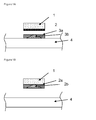
- explosive charge (1) is in contact with metal projectile strip (2) that is intended to impact on a strip of shockwave refraction tape (3) which is in direct contact with material to be cut (4). Due to the use of a projectile strip (2) intense shockwaves can be created upon impact with the shockwave refraction tape. Acceleration of projectile (2) may be achieved using either a high explosive or a binary explosive charge (1).
- Figure 3 shows an embodiment of the invention using a specially shaped metal projectile strip (5) that is to impact material to be cut (4) directly.
- the edges of the strip will impact material to be cut (4) first, followed by material closer to the symmetry-line of the projectile (5). At high enough impact velocity this will create two converging shockwaves in material to be cut (4), avoiding the use of a wave-shaping element (3).
- the invention is directed to an explosive cutting device.
- the explosive cutting device can be used in the explosive cutting method of the invention.
- the explosive cutting device comprises a holding element, said holding element holding a projectile which projectile is provided with an explosive charge connected to detonating means for detonating said explosive charge and accelerating the projectile in the direction of an object to be cut, wherein
Landscapes
- Engineering & Computer Science (AREA)
- Life Sciences & Earth Sciences (AREA)
- Forests & Forestry (AREA)
- Mechanical Engineering (AREA)
- General Engineering & Computer Science (AREA)
- Perforating, Stamping-Out Or Severing By Means Other Than Cutting (AREA)
- Working Measures On Existing Buildindgs (AREA)
Priority Applications (4)
| Application Number | Priority Date | Filing Date | Title |
|---|---|---|---|
| EP10178298A EP2434251A1 (de) | 2010-09-22 | 2010-09-22 | Sprengschneiden |
| PCT/NL2011/050642 WO2012039617A1 (en) | 2010-09-22 | 2011-09-22 | Explosive cutting |
| US13/825,490 US9163914B2 (en) | 2010-09-22 | 2011-09-22 | Explosive cutting |
| EP11764359.3A EP2619522B1 (de) | 2010-09-22 | 2011-09-22 | Sprengschneiden |
Applications Claiming Priority (1)
| Application Number | Priority Date | Filing Date | Title |
|---|---|---|---|
| EP10178298A EP2434251A1 (de) | 2010-09-22 | 2010-09-22 | Sprengschneiden |
Publications (1)
| Publication Number | Publication Date |
|---|---|
| EP2434251A1 true EP2434251A1 (de) | 2012-03-28 |
Family
ID=43533539
Family Applications (2)
| Application Number | Title | Priority Date | Filing Date |
|---|---|---|---|
| EP10178298A Withdrawn EP2434251A1 (de) | 2010-09-22 | 2010-09-22 | Sprengschneiden |
| EP11764359.3A Not-in-force EP2619522B1 (de) | 2010-09-22 | 2011-09-22 | Sprengschneiden |
Family Applications After (1)
| Application Number | Title | Priority Date | Filing Date |
|---|---|---|---|
| EP11764359.3A Not-in-force EP2619522B1 (de) | 2010-09-22 | 2011-09-22 | Sprengschneiden |
Country Status (3)
| Country | Link |
|---|---|
| US (1) | US9163914B2 (de) |
| EP (2) | EP2434251A1 (de) |
| WO (1) | WO2012039617A1 (de) |
Families Citing this family (2)
| Publication number | Priority date | Publication date | Assignee | Title |
|---|---|---|---|---|
| NZ725004A (en) * | 2014-08-06 | 2018-06-29 | Alba Mfg Corp | An explosive booster |
| US10036616B2 (en) * | 2016-02-23 | 2018-07-31 | Lawrence Livermore National Security, Llc | Architected materials and structures to control shock output characteristics |
Citations (6)
| Publication number | Priority date | Publication date | Assignee | Title |
|---|---|---|---|---|
| US3076408A (en) * | 1958-06-11 | 1963-02-05 | Borg Warner | Controlled fracturing of solids by explosives |
| US3517615A (en) * | 1961-07-14 | 1970-06-30 | Us Navy | Explosive wave shaper |
| EP0043215A1 (de) | 1980-06-28 | 1982-01-06 | Alflex Limited | Einrichtung zum Explosionsschneiden |
| WO1986007000A1 (en) | 1985-05-28 | 1986-12-04 | Explosive Developments Limited | Explosive cutting means |
| WO1988002470A2 (en) * | 1986-09-29 | 1988-04-07 | Explosive Developments Limited | Method for detonating an explosive charge |
| WO1989009376A1 (en) | 1988-03-24 | 1989-10-05 | The University Of Manchester Institute Of Science | Explosive cutting device with waveguide |
Family Cites Families (8)
| Publication number | Priority date | Publication date | Assignee | Title |
|---|---|---|---|---|
| US1191357A (en) * | 1915-08-09 | 1916-07-18 | Parke T Snyder | Cartridge-projectile. |
| US2307369A (en) * | 1941-04-22 | 1943-01-05 | Clyde B Ferrel | Projectile |
| US2424934A (en) * | 1944-11-17 | 1947-07-29 | Melvin E Kasper | Projectile |
| US3490372A (en) * | 1966-11-09 | 1970-01-20 | Arthur A Lavine | Projectile acceleration arrangement |
| US3435763A (en) * | 1967-06-20 | 1969-04-01 | Arthur A Lavine | Explosive arrangement for generating a mach stem to affect a line cut |
| IL37938A (en) * | 1970-10-19 | 1975-08-31 | Digid Ministerio De Defensa De | Self-propelling ballistic projectile totally expelled upon firing |
| WO2005095884A1 (en) * | 2004-04-02 | 2005-10-13 | Techventure Investments Pty Ltd | A projectile |
| US8037828B1 (en) * | 2008-12-17 | 2011-10-18 | Sandia Corporation | Projectile-generating explosive access tool |
-
2010
- 2010-09-22 EP EP10178298A patent/EP2434251A1/de not_active Withdrawn
-
2011
- 2011-09-22 US US13/825,490 patent/US9163914B2/en not_active Expired - Fee Related
- 2011-09-22 WO PCT/NL2011/050642 patent/WO2012039617A1/en active Application Filing
- 2011-09-22 EP EP11764359.3A patent/EP2619522B1/de not_active Not-in-force
Patent Citations (6)
| Publication number | Priority date | Publication date | Assignee | Title |
|---|---|---|---|---|
| US3076408A (en) * | 1958-06-11 | 1963-02-05 | Borg Warner | Controlled fracturing of solids by explosives |
| US3517615A (en) * | 1961-07-14 | 1970-06-30 | Us Navy | Explosive wave shaper |
| EP0043215A1 (de) | 1980-06-28 | 1982-01-06 | Alflex Limited | Einrichtung zum Explosionsschneiden |
| WO1986007000A1 (en) | 1985-05-28 | 1986-12-04 | Explosive Developments Limited | Explosive cutting means |
| WO1988002470A2 (en) * | 1986-09-29 | 1988-04-07 | Explosive Developments Limited | Method for detonating an explosive charge |
| WO1989009376A1 (en) | 1988-03-24 | 1989-10-05 | The University Of Manchester Institute Of Science | Explosive cutting device with waveguide |
Non-Patent Citations (1)
| Title |
|---|
| J. KOHLER; R. MEYER; A. HOMBURG: "Explosives, Sixth Completely", 2007, WILEY-VHC VERLAG GMBH, pages: 72 |
Also Published As
| Publication number | Publication date |
|---|---|
| EP2619522A1 (de) | 2013-07-31 |
| US9163914B2 (en) | 2015-10-20 |
| WO2012039617A1 (en) | 2012-03-29 |
| US20130233194A1 (en) | 2013-09-12 |
| EP2619522B1 (de) | 2014-06-18 |
Similar Documents
| Publication | Publication Date | Title |
|---|---|---|
| US8459185B1 (en) | Projectile-generating explosive access tool | |
| Walley et al. | Crystal sensitivities of energetic materials | |
| US6439127B1 (en) | Penetrating projectile for bomb disablement | |
| US5814758A (en) | Apparatus for discharging a high speed jet to penetrate a target | |
| US6016753A (en) | Explosive pipe cutting | |
| US8091479B1 (en) | Fluid blade disablement tool | |
| JPH05501147A (ja) | 直線状の切断・破砕を行う爆破装置 | |
| EP1734334A1 (de) | Sprengverfahren | |
| US6467416B1 (en) | Combined high-blast/anti-armor warheads | |
| CA2043926C (en) | Adhesive secondary blasting cone | |
| EP2619522B1 (de) | Sprengschneiden | |
| US9371709B2 (en) | Downhole severing tool | |
| RU2119398C1 (ru) | Способ взрывного разрезания твердых материалов и устройство для его осуществления | |
| US20110283872A1 (en) | Downhole severing tool | |
| Davis | Introduction to explosives | |
| Burch | Determining and mitigating the effects of firing a linear shaped charge under water | |
| US3626850A (en) | Explosive assembly | |
| RU2100750C1 (ru) | Способ разрушения взрывоопасных предметов и устройство для его осуществления | |
| Jaansalu et al. | Fragment velocities from thermobaric explosives in metal cylinders | |
| Yusof et al. | PREDICTION OF AIR BLAST PRESSURE FOR MILITARY AND COMMERCIAL EXPLOSIVE USING ANSYS AUTODYN. | |
| RU2070707C1 (ru) | Разрывной заряд | |
| Rinehart | Historical perspective: metallurgical effects of high strain-rate deformation and fabrication | |
| RU2144172C1 (ru) | Линейный заряд | |
| Miller | Abrasive waterjets—a nontraditional process for the safe and environmentally friendly demilitarization of underwater high-explosive munitions | |
| US9010249B2 (en) | Explosive bulk charge |
Legal Events
| Date | Code | Title | Description |
|---|---|---|---|
| PUAI | Public reference made under article 153(3) epc to a published international application that has entered the european phase |
Free format text: ORIGINAL CODE: 0009012 |
|
| AK | Designated contracting states |
Kind code of ref document: A1 Designated state(s): AL AT BE BG CH CY CZ DE DK EE ES FI FR GB GR HR HU IE IS IT LI LT LU LV MC MK MT NL NO PL PT RO SE SI SK SM TR |
|
| AX | Request for extension of the european patent |
Extension state: BA ME RS |
|
| STAA | Information on the status of an ep patent application or granted ep patent |
Free format text: STATUS: THE APPLICATION IS DEEMED TO BE WITHDRAWN |
|
| 18D | Application deemed to be withdrawn |
Effective date: 20120929 |