EP0260698B2 - Receptacle hand grip, especially for crates - Google Patents
Receptacle hand grip, especially for crates Download PDFInfo
- Publication number
- EP0260698B2 EP0260698B2 EP87113639A EP87113639A EP0260698B2 EP 0260698 B2 EP0260698 B2 EP 0260698B2 EP 87113639 A EP87113639 A EP 87113639A EP 87113639 A EP87113639 A EP 87113639A EP 0260698 B2 EP0260698 B2 EP 0260698B2
- Authority
- EP
- European Patent Office
- Prior art keywords
- lamellas
- case according
- case
- web
- grip
- Prior art date
- Legal status (The legal status is an assumption and is not a legal conclusion. Google has not performed a legal analysis and makes no representation as to the accuracy of the status listed.)
- Expired - Lifetime
Links
Images


Classifications
-
- B—PERFORMING OPERATIONS; TRANSPORTING
- B65—CONVEYING; PACKING; STORING; HANDLING THIN OR FILAMENTARY MATERIAL
- B65D—CONTAINERS FOR STORAGE OR TRANSPORT OF ARTICLES OR MATERIALS, e.g. BAGS, BARRELS, BOTTLES, BOXES, CANS, CARTONS, CRATES, DRUMS, JARS, TANKS, HOPPERS, FORWARDING CONTAINERS; ACCESSORIES, CLOSURES, OR FITTINGS THEREFOR; PACKAGING ELEMENTS; PACKAGES
- B65D1/00—Containers having bodies formed in one piece, e.g. by casting metallic material, by moulding plastics, by blowing vitreous material, by throwing ceramic material, by moulding pulped fibrous material, by deep-drawing operations performed on sheet material
- B65D1/22—Boxes or like containers with side walls of substantial depth for enclosing contents
- B65D1/24—Boxes or like containers with side walls of substantial depth for enclosing contents with moulded compartments or partitions
- B65D1/243—Crates for bottles or like containers
-
- B—PERFORMING OPERATIONS; TRANSPORTING
- B65—CONVEYING; PACKING; STORING; HANDLING THIN OR FILAMENTARY MATERIAL
- B65D—CONTAINERS FOR STORAGE OR TRANSPORT OF ARTICLES OR MATERIALS, e.g. BAGS, BARRELS, BOTTLES, BOXES, CANS, CARTONS, CRATES, DRUMS, JARS, TANKS, HOPPERS, FORWARDING CONTAINERS; ACCESSORIES, CLOSURES, OR FITTINGS THEREFOR; PACKAGING ELEMENTS; PACKAGES
- B65D2501/00—Containers having bodies formed in one piece
- B65D2501/24—Boxes or like containers with moulded compartments or partitions
- B65D2501/24006—Details relating to bottle crates
- B65D2501/24012—Materials
- B65D2501/24019—Mainly plastics
-
- B—PERFORMING OPERATIONS; TRANSPORTING
- B65—CONVEYING; PACKING; STORING; HANDLING THIN OR FILAMENTARY MATERIAL
- B65D—CONTAINERS FOR STORAGE OR TRANSPORT OF ARTICLES OR MATERIALS, e.g. BAGS, BARRELS, BOTTLES, BOXES, CANS, CARTONS, CRATES, DRUMS, JARS, TANKS, HOPPERS, FORWARDING CONTAINERS; ACCESSORIES, CLOSURES, OR FITTINGS THEREFOR; PACKAGING ELEMENTS; PACKAGES
- B65D2501/00—Containers having bodies formed in one piece
- B65D2501/24—Boxes or like containers with moulded compartments or partitions
- B65D2501/24006—Details relating to bottle crates
- B65D2501/2405—Construction
- B65D2501/24063—Construction of the walls
- B65D2501/2407—Apertured
-
- B—PERFORMING OPERATIONS; TRANSPORTING
- B65—CONVEYING; PACKING; STORING; HANDLING THIN OR FILAMENTARY MATERIAL
- B65D—CONTAINERS FOR STORAGE OR TRANSPORT OF ARTICLES OR MATERIALS, e.g. BAGS, BARRELS, BOTTLES, BOXES, CANS, CARTONS, CRATES, DRUMS, JARS, TANKS, HOPPERS, FORWARDING CONTAINERS; ACCESSORIES, CLOSURES, OR FITTINGS THEREFOR; PACKAGING ELEMENTS; PACKAGES
- B65D2501/00—Containers having bodies formed in one piece
- B65D2501/24—Boxes or like containers with moulded compartments or partitions
- B65D2501/24006—Details relating to bottle crates
- B65D2501/24197—Arrangements for locating the bottles
- B65D2501/24203—Construction of locating arrangements
- B65D2501/2421—Partitions
- B65D2501/24216—Partitions forming square or rectangular cells
-
- B—PERFORMING OPERATIONS; TRANSPORTING
- B65—CONVEYING; PACKING; STORING; HANDLING THIN OR FILAMENTARY MATERIAL
- B65D—CONTAINERS FOR STORAGE OR TRANSPORT OF ARTICLES OR MATERIALS, e.g. BAGS, BARRELS, BOTTLES, BOXES, CANS, CARTONS, CRATES, DRUMS, JARS, TANKS, HOPPERS, FORWARDING CONTAINERS; ACCESSORIES, CLOSURES, OR FITTINGS THEREFOR; PACKAGING ELEMENTS; PACKAGES
- B65D2501/00—Containers having bodies formed in one piece
- B65D2501/24—Boxes or like containers with moulded compartments or partitions
- B65D2501/24006—Details relating to bottle crates
- B65D2501/24197—Arrangements for locating the bottles
- B65D2501/24203—Construction of locating arrangements
- B65D2501/24261—Ribs on the side walls
-
- B—PERFORMING OPERATIONS; TRANSPORTING
- B65—CONVEYING; PACKING; STORING; HANDLING THIN OR FILAMENTARY MATERIAL
- B65D—CONTAINERS FOR STORAGE OR TRANSPORT OF ARTICLES OR MATERIALS, e.g. BAGS, BARRELS, BOTTLES, BOXES, CANS, CARTONS, CRATES, DRUMS, JARS, TANKS, HOPPERS, FORWARDING CONTAINERS; ACCESSORIES, CLOSURES, OR FITTINGS THEREFOR; PACKAGING ELEMENTS; PACKAGES
- B65D2501/00—Containers having bodies formed in one piece
- B65D2501/24—Boxes or like containers with moulded compartments or partitions
- B65D2501/24006—Details relating to bottle crates
- B65D2501/24197—Arrangements for locating the bottles
- B65D2501/24343—Position pattern
-
- B—PERFORMING OPERATIONS; TRANSPORTING
- B65—CONVEYING; PACKING; STORING; HANDLING THIN OR FILAMENTARY MATERIAL
- B65D—CONTAINERS FOR STORAGE OR TRANSPORT OF ARTICLES OR MATERIALS, e.g. BAGS, BARRELS, BOTTLES, BOXES, CANS, CARTONS, CRATES, DRUMS, JARS, TANKS, HOPPERS, FORWARDING CONTAINERS; ACCESSORIES, CLOSURES, OR FITTINGS THEREFOR; PACKAGING ELEMENTS; PACKAGES
- B65D2501/00—Containers having bodies formed in one piece
- B65D2501/24—Boxes or like containers with moulded compartments or partitions
- B65D2501/24006—Details relating to bottle crates
- B65D2501/24363—Handles
- B65D2501/24509—Integral handles
- B65D2501/24528—Integral handles centrally located in open container
-
- B—PERFORMING OPERATIONS; TRANSPORTING
- B65—CONVEYING; PACKING; STORING; HANDLING THIN OR FILAMENTARY MATERIAL
- B65D—CONTAINERS FOR STORAGE OR TRANSPORT OF ARTICLES OR MATERIALS, e.g. BAGS, BARRELS, BOTTLES, BOXES, CANS, CARTONS, CRATES, DRUMS, JARS, TANKS, HOPPERS, FORWARDING CONTAINERS; ACCESSORIES, CLOSURES, OR FITTINGS THEREFOR; PACKAGING ELEMENTS; PACKAGES
- B65D2501/00—Containers having bodies formed in one piece
- B65D2501/24—Boxes or like containers with moulded compartments or partitions
- B65D2501/24006—Details relating to bottle crates
- B65D2501/24363—Handles
- B65D2501/24509—Integral handles
- B65D2501/24535—Integral handles formed in the walls, e.g. roughnings, cavities or projections
-
- B—PERFORMING OPERATIONS; TRANSPORTING
- B65—CONVEYING; PACKING; STORING; HANDLING THIN OR FILAMENTARY MATERIAL
- B65D—CONTAINERS FOR STORAGE OR TRANSPORT OF ARTICLES OR MATERIALS, e.g. BAGS, BARRELS, BOTTLES, BOXES, CANS, CARTONS, CRATES, DRUMS, JARS, TANKS, HOPPERS, FORWARDING CONTAINERS; ACCESSORIES, CLOSURES, OR FITTINGS THEREFOR; PACKAGING ELEMENTS; PACKAGES
- B65D2501/00—Containers having bodies formed in one piece
- B65D2501/24—Boxes or like containers with moulded compartments or partitions
- B65D2501/24006—Details relating to bottle crates
- B65D2501/24363—Handles
- B65D2501/24541—Hand holes
-
- B—PERFORMING OPERATIONS; TRANSPORTING
- B65—CONVEYING; PACKING; STORING; HANDLING THIN OR FILAMENTARY MATERIAL
- B65D—CONTAINERS FOR STORAGE OR TRANSPORT OF ARTICLES OR MATERIALS, e.g. BAGS, BARRELS, BOTTLES, BOXES, CANS, CARTONS, CRATES, DRUMS, JARS, TANKS, HOPPERS, FORWARDING CONTAINERS; ACCESSORIES, CLOSURES, OR FITTINGS THEREFOR; PACKAGING ELEMENTS; PACKAGES
- B65D2501/00—Containers having bodies formed in one piece
- B65D2501/24—Boxes or like containers with moulded compartments or partitions
- B65D2501/24006—Details relating to bottle crates
- B65D2501/24764—Reinforcements
- B65D2501/2477—Parts reinforced
-
- B—PERFORMING OPERATIONS; TRANSPORTING
- B65—CONVEYING; PACKING; STORING; HANDLING THIN OR FILAMENTARY MATERIAL
- B65D—CONTAINERS FOR STORAGE OR TRANSPORT OF ARTICLES OR MATERIALS, e.g. BAGS, BARRELS, BOTTLES, BOXES, CANS, CARTONS, CRATES, DRUMS, JARS, TANKS, HOPPERS, FORWARDING CONTAINERS; ACCESSORIES, CLOSURES, OR FITTINGS THEREFOR; PACKAGING ELEMENTS; PACKAGES
- B65D2501/00—Containers having bodies formed in one piece
- B65D2501/24—Boxes or like containers with moulded compartments or partitions
- B65D2501/24006—Details relating to bottle crates
- B65D2501/24764—Reinforcements
- B65D2501/24789—Means used for reinforcing
- B65D2501/24796—Plain integral ribs
Definitions
- the invention relates to a plastic bottle crate according to the preamble of patent claim 1.
- bottle crates which are predominantly injection-molded in one piece from plastic
- the most varied of embodiments are known, but all of them have in common that at least one handle, primarily in one of the side walls, is provided which facilitates the handling of the crate, in particular its transportation.
- the predominant handle design is that a through opening is provided in a side wall near the upper edge of the box, which delimits a spar-like handle body between itself and the upper box edge. To grasp the box, one grips the hand from above over the upper edge of the box and reaches through the handle opening with the fingers so that the hand encloses the spar-like upper box edge and thus the box can be lifted and transported.
- Another disadvantage of the conventional bottle crate for the carrying behavior is that the upper crates of the crate are mostly profiled for reasons of stabilizing the side walls and also the grip areas of the crates, so that when the crates are gripped, one grips the profile edges of the profiles by hand, which press into the hand with the appropriate weight of the boxes.
- the object of the invention is to provide a bottle crate which, with sufficient stability, ensures a material-saving grip design compared to a full profile, which enables bottle crates to be carried comfortably.
- the grip areas of a handle are divided into a large number of closely disputed lamellae, whereby one comes close to the ideal shape of a full profile with a closed grip surface, but nevertheless achieves a material-saving effect and a sensible production technology implementation Handles reached taking into account the cooling cycles of plastic injection molded boxes.
- the lamellae which are preferably designed with round edges, provide a quasi-closed grip surface, which makes it easier to carry even heavy bottle crates.
- the lamella formations in the area of the grip areas which are endangered for reasons of stability, lead to an increase in stability, which has an overall positive effect on the rigidity of the bottle crates.
- a handle with slats only increases the weight by about 10 to a maximum of 30%, which is extremely cheap compared to the full profile and nevertheless guarantees the advantages of the full profile.
- the lamellae can be raised in relation to the handle body, wherein they can be arranged on only one or more surfaces of the handle body and partially or over the entire circumference of the body.
- the lamellae are formed in that corresponding recesses are formed next to one another in the handle body, two adjacent recesses between them delimiting the lamellae, which advantageously runs flush with the rest of the handle body, i. H. the generators of the slats merge flush into the box wall sections adjacent to the grip area.
- the free lamellar edges are formed in the manner of knobs.
- the lamellar edges are rounded in a structurally simple manner.
- the slats are formed in a carrier element which can be retrofitted into a correspondingly profiled grip body, the protruding slats then forming the actual gripping surface of the bottle crate.
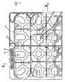
- a handle 2 is formed in the narrow side labeled 1, the T-shaped handle body 3 of which is delimited by two L-shaped through openings 4a and 4b.
- the handle body 3 is composed of a handle bar 5 on a vertical handle bar 6.
- the handle bar 6 is designed as a hollow profile, as best seen in the sectional view of FIG. 1.
- the handle bar 5 is divided on its surface facing the inside of the box and at the top of the box into individual lamellae 7, which are closely spaced and arranged parallel to one another. These lamellae 7 are formed by corresponding cutouts 8 in the handle body or in the handle bar 5, each lamella 7 being delimited by two cutouts 8.
- the handle area of the handlebar 5 is that which is when the box is carried is gripped by hand on the handle bar 5, broken down into individual, closely spaced lamellae 7. If necessary, the vertical handle bar 6 can be divided into slats.
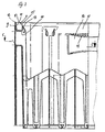
- the shape of the slats 7 or the recesses 8 is best shown in FIG. 3.
- the handle body 3 is formed in the region of the handle bar 5 from an L-shaped web 9, from the inside 10 of which the slats 7 towards the inside of the box protrude at right angles. 3 runs flush with the upper end 12 of the web 9 and the inner edge 13 of the web 7 runs essentially parallel to the web 9 and flush with the end 14 of the web 9 Gripping the box with the hand coming edge 15 of the slats 7 is rounded.
- the ends 12 and 14, into which the lamella edges merge, are also preferably rounded.
- the slats 7 are regular, that is. H. Equal to each other and have the same narrow distance from each other, so that a quasi-closed, that is to say a largely adapted to a closed grip surface is formed, which allows a comfortable gripping of the bottle crate.
- the upper handle bar 17 can also be formed with lamellae 18, but only schematically without further details are shown in Fig. 3. 3 leaves however recognize that the slats 18 are of different lengths and thus adapted to the grip surface of the hand.
- FIGS. 4 to 6 differs only slightly from the embodiment according to FIGS. 1 to 3, as far as the formation of the L-web 9 and the slats 7 are concerned.
- the L-leg 19 of the web 9 is angled upward at its front end, but here again the inner edge 13 of the lamella 7 runs flush with the rounded front end 14 of the web 9.
- Fig. 5 shows that in the area of the transition between handle bar 5 and vertical handle bar 6, the slats 7 are formed with increasing length.
- Fig. 7 shows the upper part of a box edge, which forms a U-shaped handle body 3, which is delimited below by a recess 19 in the side wall of the box. Slats 7 extend at a short distance from one another within the profile of the handle body 3, a slat 7 being visible on the basis of the sectional illustration in FIG. 7.
- the lamella 7 is convexly curved outwards in the region of the grip surface at 20.
- FIG. 8 shows only schematically different designs of lamella edges, the lamellae 7 being expanded like a mushroom at 21 at the upper end in accordance with the illustration on the left.
- the lamellae shown in the middle are round at their free lamella edges at 22, whereas the lamellae shown on the right are lump-shaped at 23 at their ends.
- these embodiments are characterized by a grip surface that is largely approximated to the closed grip surface.
- the slats can be aligned horizontally and / or vertically and / or diagonally, intersect and.
- the slats can be aligned horizontally and / or vertically and / or diagonally, intersect and.
- the slats can be aligned horizontally and / or vertically and / or diagonally, intersect and.
Description
Die Erfindung betrifft einen Flaschenkasten aus Kunststoff gemäß dem Oberbegriff des Patentanspruches 1.The invention relates to a plastic bottle crate according to the preamble of patent claim 1.
Bei Flaschenkästen, die überwiegend einstückig aus Kunststoff gespritzt werden, sind die verschiedensten Ausführungsformen bekannt, denen aber allen gemeinsam ist, daß mindestens ein Griff, vornehmlich in einer der Seitenwände, vorgesehen ist, der die Handhabung des Kastens, insbesondere dessen Transport erleichtert. Die überwiegende Griffausbildung ist die, daß in einer Seitenwand eine Durchgriffsöffnung nahe am oberen Rand des Kastens vorgesehen ist, die zwischen sich und dem oberen Kastenrand einen holmartigen Griffkörper begrenzt. Zum Ergreifen des Kastens faßt man hierbei mit der Hand von oben über den oberen Kastenrand und greift mit den Fingern durch die Grifföffnung, so daß die Hand den holmartigen oberen Kastenrand umschließt und damit der Kasten angehoben und transportiert werden kann. Bei Kästen, die mit vollen Flaschen gefüllt sind, insbesondere bei den überwiegend verwendeten 20er-Kästen, bereitet dies jedoch aufgrund des Gewichts Schwierigkeiten. Die ldealform eines Griffes als voll massiv ausgebildeter Griff läßt sich aus Gründen der erforderlichen Materialeinsparung bei aus Kunststoff gespritzten Kästen sinnvollerweise nicht realisieren. Zudem sind bei der Herstellung von Flaschenkästen bestimmte Zykluszeiten vorgegeben, die eine volle Ausformung eines Handgriffes als Vollprofil am Flaschenkasten nicht ermöglichen, zumal bei einer solchen Ausformung eines Griffes auch Abkühlungsschwierigkeiten auftreten würden. Ein voll ausgebildeter Handgriff würde zudem zu einer entsprechenden Gewichtszunahme führen und damit gerade den Bestrebungen zuwiderlaufen, den Flaschenkasten möglichst leicht auszubilden.In bottle crates, which are predominantly injection-molded in one piece from plastic, the most varied of embodiments are known, but all of them have in common that at least one handle, primarily in one of the side walls, is provided which facilitates the handling of the crate, in particular its transportation. The predominant handle design is that a through opening is provided in a side wall near the upper edge of the box, which delimits a spar-like handle body between itself and the upper box edge. To grasp the box, one grips the hand from above over the upper edge of the box and reaches through the handle opening with the fingers so that the hand encloses the spar-like upper box edge and thus the box can be lifted and transported. For crates that are filled with full bottles, especially the 20-way crates that are mainly used, this causes difficulties due to the weight. The ideal shape of a handle as a fully solid handle cannot reasonably be realized for reasons of the necessary material savings in boxes molded from plastic. In addition, certain cycle times are specified in the manufacture of bottle crates which do not allow a handle to be fully shaped as a full profile on the bottle crate, especially since such a handle would also experience cooling difficulties. A fully trained handle would also lead to a corresponding weight gain and thus run counter to the efforts to make the bottle crate as light as possible.
Ein weiterer Nachteil des herkömmlichen Flaschenkastens für das Trageverhalten besteht darin, daß die oberen Kastenränder aus Gründen der Stabilisierung der Seitenwände und auch der Griffbereiche der Kästen zumeist profiliert ausgebildet sind, so daß man beim Greifen der Kästen mit der Hand um die Profilkanten der Profile greift, die sich bei entsprechendem Gewicht der Kästen in die Hand eindrücken.Another disadvantage of the conventional bottle crate for the carrying behavior is that the upper crates of the crate are mostly profiled for reasons of stabilizing the side walls and also the grip areas of the crates, so that when the crates are gripped, one grips the profile edges of the profiles by hand, which press into the hand with the appropriate weight of the boxes.
Aufgabe der Erfindung ist es, einen Flaschenkasten zu schaffen, der bei ausreichender Stabilität eine gegenüber einem Vollprofil materialsparende Griffausbildung gewährleistet, die ein bequemes Tragen von Flaschenkästen ermöglicht.The object of the invention is to provide a bottle crate which, with sufficient stability, ensures a material-saving grip design compared to a full profile, which enables bottle crates to be carried comfortably.
Diese Aufgabe wird erfindungsgemäß durch die im kennzeichnenden Teil des Patentanspruches 1 enthaltenen Merkmale gelöst.This object is achieved by the features contained in the characterizing part of claim 1.
Nach Maßgabe der Erfindung sind die Griffbereiche eines Griffes in eine Vielzahl von eng beanstandeten Lamellen aufgegliedert, wodurch man der ldealform eines Vollprofils mit einer geschlossenen Grifffläche nahekommt, jedoch gleichwohl einen materialsparenden Effekt erreicht und eine fertigungstechnisch vernünftige Realisierung dieser Griffe unter Berücksichtigung der Abkühlzyklen von aus Kunststoff gespritzten Kästen erreicht. Die vorzugsweise mit runden Kanten ausgebildeten Lamellen erbringen eine quasi geschlossene Grifffläche, die das Tragen selbst schwerer Flaschenkästen erleichtert. Ferner führen die Lamellenausbildungen im Bereich der aus Stabilitätsgründen ohnehin gefährdeten Griffbereiche zu einer Stabilitätserhöhung, die sich insgesamt positiv auf die Steifigkeit der flaschenkästen auswirkt. Im Vergleich zu einem konventionellen Handgriff eines Flaschenkastens mit einem im Querschnitt U-förmigen Griffholm führt ein mit Lamellen vesehener Griff nur zu einer Gewichtserhöhung von etwa 10 bis maximal 30 %, was im Vergleich zum Vollprofil außerordentlich günstig ist und gleichwohl die Vorteile des Vollprofils gewährleistet.According to the invention, the grip areas of a handle are divided into a large number of closely disputed lamellae, whereby one comes close to the ideal shape of a full profile with a closed grip surface, but nevertheless achieves a material-saving effect and a sensible production technology implementation Handles reached taking into account the cooling cycles of plastic injection molded boxes. The lamellae, which are preferably designed with round edges, provide a quasi-closed grip surface, which makes it easier to carry even heavy bottle crates. Furthermore, the lamella formations in the area of the grip areas, which are endangered for reasons of stability, lead to an increase in stability, which has an overall positive effect on the rigidity of the bottle crates. Compared to a conventional handle of a bottle crate with a U-shaped handle bar, a handle with slats only increases the weight by about 10 to a maximum of 30%, which is extremely cheap compared to the full profile and nevertheless guarantees the advantages of the full profile.
Die Lamellen können gegenüber dem Griffkörper erhaben ausgebildet sein, wobei sie auf nur einer oder mehreren Flächen des Griffkörpers sowie teilweise oder über den gesamten Umfang des Körpers angeordnet sein können. Nach einer alternativen Ausführungsform sind die Lamellen dadurch gebildet, daß im Griffkörper nebeneinander entsprechende Aussparungen ausgeformt sind, wobei zwei benachbarte Aussparungen zwischen sich die Lamellen begrenzen, die zweickmäßigerweise mit dem übrigen Griffkörper bündig verläuft, d. h. die Erzeugenden der Lamellen gehen bündig in die dem Griffbereich benachbarten Kastenwandabschnitte über.The lamellae can be raised in relation to the handle body, wherein they can be arranged on only one or more surfaces of the handle body and partially or over the entire circumference of the body. According to an alternative embodiment, the lamellae are formed in that corresponding recesses are formed next to one another in the handle body, two adjacent recesses between them delimiting the lamellae, which advantageously runs flush with the rest of the handle body, i. H. the generators of the slats merge flush into the box wall sections adjacent to the grip area.
Zur Erhöhung der Grifffläche ist bevorzugt, daß die freien Lamellenränder verdickt in Art von Noppen ausgebildet sind. In konstruktiv einfacher Weise sind die Lamellenränder jedoch gerundet ausgebildet.To increase the grip area, it is preferred that the free lamellar edges are formed in the manner of knobs. However, the lamellar edges are rounded in a structurally simple manner.
Nach einer vorteilhaften Weiterbildung der Erfindung sind die Lamellen in einem Trägerelement ausgebildet, welches sich in einen entsprechend profilierten Griffkörper nachträglich einsetzen läßt, wobei die vorstehenden Lamellen dann die eigentliche Grifffläche des Flaschenkastens bilden.According to an advantageous development of the invention, the slats are formed in a carrier element which can be retrofitted into a correspondingly profiled grip body, the protruding slats then forming the actual gripping surface of the bottle crate.
Nachfolgend werden Ausführungsbeispiele der Erfindung anhand der Zeichnung beschrieben. Darin zeigen
- Fig. 1 eine Draufsicht auf einen Teil eines Flaschenkastens entsprechend einem Schnitt längs Linie C-C von Fig. 3,
- Fig. 2 eine Seitenansicht des in den Fig. 1 und 3 dargestellten Flaschenkasten, wobei die rechte Hälfte von Fig. 2 eine Ansicht von außerhalb des Flaschenkastens und die linke Hälfte von Fig.2 eine Ansicht des Flaschenkastens von innen in Richtung auf die Schmalseite zeigt, und zwar entsprechend eines Schnitts längs der Linie B-B von Fig.1
- Fig. 3 einen Teil des in den Fig. 1 und 2 dargestellten Flaschenkastens in Seitenansicht, wobei die linke Hälfte des Kastens nach Fig. 3 eine Schnittansicht längs Linie A-A von Fig. 1 zeigt,
- Fig. 4 eine weitere Ausführungsform eines Flaschenkastens in Draufsicht ähnlich der Fig. 1, wobei das obere linke Viertel eine Ansicht des Flaschenkastens von unten und die untere Hälfte eine Schnittansicht des Flaschenkastens zeigt,
- Fig. 5 eine Ansicht des in Fig. 4 dargestellten Flaschenkastens analog der Ansicht in Fig. 2,
- Fig. 6 eine Seitenansicht des in den Fig. 4 und 5 dargestellten Flaschenkastens in einer Ansicht analog der von Fig. 3,
- Fig. 7 einen Teil eines Flaschenkastens zur Darstellung eines Griffkörpers in Schnittansicht,
- Fig. 8 eine schematische Aufsicht auf einen Griffkörper mit drei alternativen Ausführungsformen von Lamellenausbildungen.
- 1 is a plan view of part of a bottle crate corresponding to a section along line CC of FIG. 3,
- 2 shows a side view of the bottle crate shown in FIGS. 1 and 3, the right half of FIG. 2 showing a view from the outside of the bottle crate and the left half of FIG. 2 showing a view of the bottle crate from the inside towards the narrow side , namely according to a section along the line BB of Fig.1
- 3 shows a part of the bottle crate shown in FIGS. 1 and 2 in a side view, the left half of the crate according to FIG. 3 showing a sectional view along line AA of FIG. 1,
- 4 shows a further embodiment of a bottle crate in plan view similar to FIG. 1, the upper left quarter showing a view of the bottle crate from below and the lower half a sectional view of the bottle crate,
- 5 is a view of the bottle crate shown in FIG. 4 analogous to the view in FIG. 2,
- 6 is a side view of the bottle crate shown in FIGS. 4 and 5 in a view analogous to that of FIG. 3,
- 7 shows a part of a bottle crate for showing a handle body in a sectional view,
- Fig. 8 is a schematic plan view of a handle body with three alternative embodiments of lamella designs.
Bei dem in den Fig. 1 bis 3 dargestellten Flaschenkasten ist in der mit 1 bezeichneten Schmalseite ein am besten aus Fig. 2 ersichtlicher Griff 2 ausgebildet, dessen T-förmiger Griffkörper 3 durch zwei L-förmige Durchgriffsöffnungen 4a und 4b begrenzt ist Der Griffkörper 3 setzt sich hierbei aus einem Griffholm 5 an einer vertikalen Griffleiste 6 zusammen. Die Griffleiste 6 ist hierbei als Hohlprofil ausgebildet, wie am besten aus der Schnittdarstellung aus Fig. 1 hervorgeht.In the bottle crate shown in FIGS. 1 to 3, a
Entsprechend den Fig. 1 und 2 ist der Griffholm 5 auf seiner dem Kasteninneren zugewandten Fläche und an der Oberseite des Kastens in einzelne Lamellen 7 aufgegliedert, die eng beabstandet und parallel zueinander angeordnet sind. Gebildet sind diese Lamellen 7 durch entsprechende Aussparungen 8 im Griffkörper bzw. im Griffholm 5, wobei jede Lamelle 7 von zwei Aussparungen 8 begrenzt ist Mithin ist bei der Ausführungsform nach den Fig. 1 bis 3 der Griffbereich des Griffholms 5, der beim Tragen des Kastens am Griffholm 5 von der Hand gefaßt wird, in einzelne eng beabstandete Lamellen 7 aufgegliedert. Bei Bedarf kann auch die vertikale Griffleiste 6 in Lamellen untergliedert sein.1 and 2, the
Die Form der Lamellen 7 bzw. der Aussparungen 8 ergibt sich am besten aus Fig. 3. Danach ist der Griffkörper 3 im Bereich des Griffholmes 5 aus einem L-förmigen Steg 9 gebildet, von dessen Innenseite 10 die Lamellen 7 in Richtung auf das Kasteninnere rechtwinkelig abstehen. Der obere Rand 11 der Lamelle 7 verläuft entsprechend Fig. 3 bündig mit dem oberen Ende 12 des Stegs 9 und der innere Rand 13 der Lamelle 7 verläuft im wesentlichen parallel zum Steg 9 und zwar bündig mit dem Ende 14 des Stegs 9. Die insbesondere beim Greifen des Kastens mit der Hand in Berührung kommende Kante 15 der Lamellen 7 ist gerundet. Auch die Enden 12 und 14, in die die Lamellenränder übergehen, sind bevorzugt gerundet ausgebildet. Beim Ausführungsbeispiel nach den Fig. 1 bis 3 sind die Lamellen 7 regelmäßig, d. h. gleich zueinander ausgebildet und weisen untereinander denselben engen Abstand auf, so daß eine quasi geschlossene, also eine einer geschlossenen Grifffläche weitgehend angepaßte Grifffläche gebildet wird, die ein komfortables Ergreifen des Flaschenkastens erlaubt.The shape of the
Neben dem T-förmigen Griff 2 in der Schmalseite 1 des Kastens ist ein weiterer, durch eine Durchgriffsöffnung 16 gebildeter Griff in der Längsseitenwand des Kastens ausgebildet, dessen oberer Griffholm 17 gleichfalls mit Lamellen 18 ausgebildet sein kann, die aber nur schema tisch ohne nähere Einzelheiten in Fig. 3 dargestellt sind. Fig. 3 läßt jedoch erkennen, daß die Lamellen 18 unterschiedlich lang und damit der Grifffläche der Hand angepaßt sind.In addition to the T-
Die Ausführungsform nach den Fig. 4 bis 6 unterscheidet sich nur geringfügig von der Ausführungsform nach den Fig. 1 bis 3, was die Ausbildung des L-Stegs 9 sowie daran angepaßt der Lamellen 7 anbelangt. Im einzelnen ist der L-Schenkel 19 des Stegs 9 an seinem vorderen Ende nach oben abgewinkelt, wobei aber hier wiederum der innere Rand 13 der Lamelle 7 bündig zum abgerundeten vorderen Ende 14 des Stegs 9 verläuft. Fig. 5 zeigt, daß im Bereich des Übergangs zwischen Griffholm 5 und vertikaler Griffleiste 6 die Lamellen 7 mit zunehmender Länge ausgebildet sind.The embodiment according to FIGS. 4 to 6 differs only slightly from the embodiment according to FIGS. 1 to 3, as far as the formation of the L-
Fig. 7 zeigt den oberen Teil eines Kastenrandes, der einen U-förmigen Griffkörper 3 bildet, der unten von einer Ausnehmung 19 in der Seitenwand des Kastens begrenzt ist. Lamellen 7 erstrecken sich mit geringem Abstand zueinander innerhalb des Profils des Griffkörpers 3, wobei aufgrund der Schnittdarstellung in Fig. 7 eine Lamelle 7 ersichtlich ist. Die Lamelle 7 ist im Bereich der Grifffläche bei 20 ballig nach außen gewölbt.Fig. 7 shows the upper part of a box edge, which forms a
Fig. 8 zeigt nur schematisch verschiedene Ausbildungen von Lamellenrändern, wobei die Lamellen 7 entsprechend der linken Darstellung am oberen Ende pilzförmig bei 21 aufgeweitet sind. Die in der Mitte dargestellten Lamellen sind an ihren freien Lamellenrändern bei 22 rund ausgebildet, wohingegen die rechts dargestellten Lamellen an ihren Enden bei 23 noppenförmig ausgebildet sind. Aufgrund der seitlichen Aufweitung der freien Lamellenränder 21 und 23 sind diese Ausführungsformen durch eine der geschlossenen Grifffläche weitgehend angenäherte Grifffläche gekennzeichnet. Selbstverständlich sind weitere Abweichungen der Lamellenform und der Lamellenanordnung möglich, insbesondere können die Lamellen horizontal und/oder vertikal und/oder diagonal ausgerichtet sein, sich kreuzen u. dgl..FIG. 8 shows only schematically different designs of lamella edges, the
Claims (15)
- Bottle case of plastic material having at least one integrally moulded grip for transporting the case, characterised in that at least one grip of the case is designed with a plurality of closely spaced lamellas (7) on at least one section of said case.
- Case according to claim 1, chracterised in that the lamellas (7) are arranged parallel to each other.
- Case according to claim 1 or 2, characterised in that the lamellas are formed by spaced recesses (8) in the grip body (3), every two of said recesses defining between themselves a lamella (7).
- Case according to any of the preceding claims, characterised in that the lamellas (7) are flake-shaped.
- Case according to any of the preceding claims, characterised in that the lamella edge (11,13) is flush with the grip body (3).
- Case according to any of the preceding claims, characterised in that the lamellas (7) have round edges.
- Case according to any of the preceding claims, characterised in that the lamellas (7) are disposed on one or more of the surfaces of the grip body (3), predominantly on one or both of the wide surfaces of the grip body (3).
- Case according to any of the preceding claims, characterised in that the lamellas (7) extend vertically, horizontally and/or diagonally relative to the bottle case.
- Case according to any of the preceding claims, characterised in that the lamellas (7) protrude at right angles from the grip body (3).
- Case according to any of the preceding claims, characterised in that the lamellas (7) are different in height and thus conform to the hand vault or to the finger limbs.
- Case according to any of the preceding claims, characterised in that the grip body (3) is formed by a web-like profile (9) in the region of the lamellar portion and that the lamellas (7) extend away from at least one side of the web.
- Case according to claim 11, characterised in that the web-like profile is defined by an L-shaped web (9), from whose inside (10) the lamellas (7) project, and that the length and the width of the lamellas correspond to the height of the web and to the length of the L-shaped leg in such manner that the lamella edges (11,13) are in aligned transition to the ends (12) and (14) respectively of the web (9).
- Case according to any of the preceding claims, characterised in that the lamellas are arranged with respect to each other at distances such that a substantially closed grip surface is formed.
- Case according to any of the preceding claims, characterised in that the free edges of the lamellas are rounded or provided with knubs (21,23).
- Case according to any of the preceding claims, characterised in that the lamellas (7) are arranged on a carrier element which may be inserted into a correspondingly profilated grip body (3) in such manner that the lamellas (7) define the grip surface.
Applications Claiming Priority (2)
| Application Number | Priority Date | Filing Date | Title |
|---|---|---|---|
| DE3631775 | 1986-09-18 | ||
| DE3631775 | 1986-09-18 |
Publications (3)
| Publication Number | Publication Date |
|---|---|
| EP0260698A1 EP0260698A1 (en) | 1988-03-23 |
| EP0260698B1 EP0260698B1 (en) | 1989-12-20 |
| EP0260698B2 true EP0260698B2 (en) | 1996-10-30 |
Family
ID=6309859
Family Applications (1)
| Application Number | Title | Priority Date | Filing Date |
|---|---|---|---|
| EP87113639A Expired - Lifetime EP0260698B2 (en) | 1986-09-18 | 1987-09-17 | Receptacle hand grip, especially for crates |
Country Status (2)
| Country | Link |
|---|---|
| EP (1) | EP0260698B2 (en) |
| DE (2) | DE3761198D1 (en) |
Families Citing this family (19)
| Publication number | Priority date | Publication date | Assignee | Title |
|---|---|---|---|---|
| DE8717618U1 (en) * | 1987-01-15 | 1989-06-08 | Alexander Schoeller & Co. Ag, Romont, Ch | |
| DE3823650A1 (en) * | 1988-07-13 | 1990-01-18 | Theysohn Friedrich Fa | Plastic bottle crate |
| DE3841339C3 (en) * | 1988-12-08 | 1997-07-17 | Delbrouck Franz Gmbh | Stackable plastic bottle crate |
| DE4017907A1 (en) * | 1990-06-02 | 1991-12-05 | Wilhelm Goetz | HANDLE TO CARRY AN OBJECT |
| DE4036141A1 (en) * | 1990-11-13 | 1992-05-14 | Peguform Werke Gmbh | PLASTIC BOTTLE BOX |
| DE4039058C2 (en) * | 1990-12-07 | 1994-11-24 | Peguform Werke Gmbh | Transport containers, in particular plastic bottle crates |
| DE4217343C2 (en) * | 1992-05-26 | 1995-12-14 | Theysohn Friedrich Fa | Injection mold for producing a molded part made of plastic |
| USD370999S (en) | 1992-07-16 | 1996-06-25 | Schoeller-Plast Sa | Crate hand grip |
| DE4236781A1 (en) * | 1992-10-30 | 1994-05-05 | Schoeller Plast Ag | Bottle case with carrying grips - is of plastic with grip openings in side walls and limited upwardly by grip section. |
| DE19525000C1 (en) * | 1995-07-08 | 1997-01-30 | Theysohn Friedrich Fa | Injection mold for the production of a box made of plastic |
| NL1010724C2 (en) | 1998-12-04 | 2000-06-06 | Wavin Trepak B V | Double walled crate for bottles is made from injection molded plastic and has softened handgrips to minimize discomfort for user |
| DE10252648A1 (en) * | 2002-09-09 | 2004-05-27 | Theysohn Formenbau Gmbh | Container molding process, particularly for a grip or base area of a bottle crate, involves molding a first section on a container and transfer to a second tool whose slides form cavities for molding second sections |
| PT1431193E (en) * | 2002-12-16 | 2013-05-07 | Dw Plastics N V | Container handles |
| DE10328392A1 (en) * | 2003-06-24 | 2005-01-20 | Schoeller Wavin Systems Services Gmbh | Plastic container with insert and method for its production |
| DE102005026112B4 (en) * | 2005-06-04 | 2016-05-12 | Linpac Allibert Gmbh | Plastic transport box |
| AT503830B1 (en) * | 2006-06-21 | 2008-09-15 | Haidlmair Ges M B H | TRANSPORT BOX AND SPRAYER FOR A TRANSPORT BOX |
| DE102008015382A1 (en) * | 2008-03-20 | 2009-09-24 | Linpac Allibert Gmbh | Integrally made of plastic bottle carrier and serving for its production mold |
| CN102596732B (en) * | 2009-10-28 | 2014-12-24 | 埃弗科系统有限责任公司 | Transport and presentation box |
| MA34905B1 (en) * | 2011-02-10 | 2014-02-01 | Ifco Systems Gmbh | TRANSPORTATION AND PRESENTATION BOX |
Family Cites Families (1)
| Publication number | Priority date | Publication date | Assignee | Title |
|---|---|---|---|---|
| DE2718067C2 (en) * | 1977-04-22 | 1983-06-01 | Alexander Schoeller & Co AG, Volketswil, Schwerzenbach | Stackable plastic bottle crate |
-
1987
- 1987-09-17 DE DE8787113639T patent/DE3761198D1/en not_active Expired - Lifetime
- 1987-09-17 DE DE8717802U patent/DE8717802U1/de not_active Expired - Lifetime
- 1987-09-17 EP EP87113639A patent/EP0260698B2/en not_active Expired - Lifetime
Also Published As
| Publication number | Publication date |
|---|---|
| DE3761198D1 (en) | 1990-01-25 |
| DE8717802U1 (en) | 1990-05-23 |
| EP0260698B1 (en) | 1989-12-20 |
| EP0260698A1 (en) | 1988-03-23 |
Similar Documents
| Publication | Publication Date | Title |
|---|---|---|
| EP0260698B2 (en) | Receptacle hand grip, especially for crates | |
| DE19605080B4 (en) | Transport container with releasably lockable hinged walls | |
| DE1586815C3 (en) | Bottle carrier | |
| DE102008047859A1 (en) | large containers | |
| EP1060999A2 (en) | Container, in particular for transporting fruits and vegetables | |
| DE3517089C2 (en) | Containers, in particular rotary stacking containers | |
| EP0566983A1 (en) | Luggage case | |
| DE20313077U1 (en) | Method for reinforcing the handgrips in a plastic box by including a pressure injected hollow chamber through the support rib structure over the handgrips | |
| DE1296081C2 (en) | Transport box system with boxes of different sizes | |
| DE202008005791U1 (en) | Transport and storage container with locking device | |
| EP0348750B1 (en) | Bottle case | |
| EP0603531B1 (en) | Plastic bottle crate with handle | |
| EP0258549B2 (en) | Stackable bottle crate | |
| DE2819678C2 (en) | Plastic transport box | |
| EP0599028B1 (en) | Bottle crate | |
| EP0585535B1 (en) | Stackable plastic crate | |
| DE102008020916A1 (en) | Integrally made of plastic transport box | |
| DE4411648A1 (en) | Stackable transport container for transporting along roller tracks | |
| CH496159A (en) | Plastic roller shutter slat | |
| DE4411647A1 (en) | Transport container stackable in cross=linked stacks | |
| EP0087563B1 (en) | Strip with locks | |
| DE19753420A1 (en) | Beverage crate with crown cap opener | |
| EP0460367A2 (en) | Hand grip for carrying an article | |
| DE1902439C (en) | Drawer for furniture | |
| DE8432997U1 (en) | Transport and / or storage box |
Legal Events
| Date | Code | Title | Description |
|---|---|---|---|
| PUAI | Public reference made under article 153(3) epc to a published international application that has entered the european phase |
Free format text: ORIGINAL CODE: 0009012 |
|
| AK | Designated contracting states |
Kind code of ref document: A1 Designated state(s): BE DE NL |
|
| 17P | Request for examination filed |
Effective date: 19880223 |
|
| 17Q | First examination report despatched |
Effective date: 19890123 |
|
| GRAA | (expected) grant |
Free format text: ORIGINAL CODE: 0009210 |
|
| AK | Designated contracting states |
Kind code of ref document: B1 Designated state(s): BE DE NL |
|
| REF | Corresponds to: |
Ref document number: 3761198 Country of ref document: DE Date of ref document: 19900125 |
|
| RAP2 | Party data changed (patent owner data changed or rights of a patent transferred) |
Owner name: SCHOELLER-PLAST AG |
|
| NLT1 | Nl: modifications of names registered in virtue of documents presented to the patent office pursuant to art. 16 a, paragraph 1 |
Owner name: SCHOELLER-PLAST SA (SCHOELLER-PLAST AG) TE ROMONT, |
|
| PLBI | Opposition filed |
Free format text: ORIGINAL CODE: 0009260 |
|
| PLBI | Opposition filed |
Free format text: ORIGINAL CODE: 0009260 |
|
| 26 | Opposition filed |
Opponent name: OBERLAND PLASTIC GMBH Effective date: 19900913 |
|
| 26 | Opposition filed |
Opponent name: FRANZ DELBROUCK GMBH Effective date: 19900918 Opponent name: BEROLINA KUNSTSTOFF GMBH Effective date: 19900918 Opponent name: OBERLAND PLASTIC GMBH Effective date: 19900913 |
|
| NLR1 | Nl: opposition has been filed with the epo |
Opponent name: OBERLAND PLASTIC GMBH |
|
| NLR1 | Nl: opposition has been filed with the epo |
Opponent name: FRANZ DELBROUCK GMBH Opponent name: BEROLINA KUNSTSTOFF GMBH |
|
| PLBI | Opposition filed |
Free format text: ORIGINAL CODE: 0009260 |
|
| 26 | Opposition filed |
Opponent name: SYSTEMPACK WALTER SCHLEGEL Effective date: 19930203 Opponent name: FRANZ DELBROUCK GMBH Effective date: 19900918 Opponent name: BEROLINA KUNSTSTOFF GMBH Effective date: 19900918 Opponent name: OBERLAND PLASTIC GMBH Effective date: 19900913 |
|
| NLR1 | Nl: opposition has been filed with the epo |
Opponent name: SYSTEMPACK WALTER SCHLEGEL. |
|
| PGFP | Annual fee paid to national office [announced via postgrant information from national office to epo] |
Ref country code: NL Payment date: 19940930 Year of fee payment: 8 |
|
| PGFP | Annual fee paid to national office [announced via postgrant information from national office to epo] |
Ref country code: BE Payment date: 19941007 Year of fee payment: 8 |
|
| PG25 | Lapsed in a contracting state [announced via postgrant information from national office to epo] |
Ref country code: BE Effective date: 19950930 |
|
| PLAW | Interlocutory decision in opposition |
Free format text: ORIGINAL CODE: EPIDOS IDOP |
|
| BERE | Be: lapsed |
Owner name: SCHOELLER-PLAST A.G. Effective date: 19950930 |
|
| PG25 | Lapsed in a contracting state [announced via postgrant information from national office to epo] |
Ref country code: NL Effective date: 19960401 |
|
| NLV4 | Nl: lapsed or anulled due to non-payment of the annual fee |
Effective date: 19960401 |
|
| PLAW | Interlocutory decision in opposition |
Free format text: ORIGINAL CODE: EPIDOS IDOP |
|
| PUAH | Patent maintained in amended form |
Free format text: ORIGINAL CODE: 0009272 |
|
| STAA | Information on the status of an ep patent application or granted ep patent |
Free format text: STATUS: PATENT MAINTAINED AS AMENDED |
|
| 27A | Patent maintained in amended form |
Effective date: 19961030 |
|
| AK | Designated contracting states |
Kind code of ref document: B2 Designated state(s): BE DE NL |
|
| PGFP | Annual fee paid to national office [announced via postgrant information from national office to epo] |
Ref country code: DE Payment date: 20061128 Year of fee payment: 20 |