EP0260529B2 - Elektrodenverbindung - Google Patents
Elektrodenverbindung Download PDFInfo
- Publication number
- EP0260529B2 EP0260529B2 EP87112798A EP87112798A EP0260529B2 EP 0260529 B2 EP0260529 B2 EP 0260529B2 EP 87112798 A EP87112798 A EP 87112798A EP 87112798 A EP87112798 A EP 87112798A EP 0260529 B2 EP0260529 B2 EP 0260529B2
- Authority
- EP
- European Patent Office
- Prior art keywords
- electrode
- pitch
- nipple
- bonding material
- cementitious bonding
- Prior art date
- Legal status (The legal status is an assumption and is not a legal conclusion. Google has not performed a legal analysis and makes no representation as to the accuracy of the status listed.)
- Expired - Lifetime
Links
- 210000002445 nipple Anatomy 0.000 claims abstract description 40
- 239000004088 foaming agent Substances 0.000 claims abstract description 23
- 239000000203 mixture Substances 0.000 claims abstract description 19
- 239000000463 material Substances 0.000 claims abstract description 17
- 239000002245 particle Substances 0.000 claims abstract description 12
- 239000011295 pitch Substances 0.000 claims description 49
- OKTJSMMVPCPJKN-UHFFFAOYSA-N Carbon Chemical compound [C] OKTJSMMVPCPJKN-UHFFFAOYSA-N 0.000 claims description 16
- 239000000571 coke Substances 0.000 claims description 9
- 229910002804 graphite Inorganic materials 0.000 claims description 9
- 239000010439 graphite Substances 0.000 claims description 9
- 238000010891 electric arc Methods 0.000 claims description 8
- 229910052799 carbon Inorganic materials 0.000 claims description 7
- 239000011294 coal tar pitch Substances 0.000 claims description 4
- 239000011362 coarse particle Substances 0.000 claims description 4
- LXQOQPGNCGEELI-UHFFFAOYSA-N 2,4-dinitroaniline Chemical compound NC1=CC=C([N+]([O-])=O)C=C1[N+]([O-])=O LXQOQPGNCGEELI-UHFFFAOYSA-N 0.000 claims 1
- 238000006073 displacement reaction Methods 0.000 claims 1
- NINIDFKCEFEMDL-UHFFFAOYSA-N Sulfur Chemical compound [S] NINIDFKCEFEMDL-UHFFFAOYSA-N 0.000 abstract description 2
- 229910052717 sulfur Inorganic materials 0.000 abstract description 2
- 239000011593 sulfur Substances 0.000 abstract description 2
- 238000010438 heat treatment Methods 0.000 description 8
- 239000007788 liquid Substances 0.000 description 8
- 238000005187 foaming Methods 0.000 description 7
- 239000006253 pitch coke Substances 0.000 description 5
- 239000000155 melt Substances 0.000 description 4
- 238000002844 melting Methods 0.000 description 4
- 230000008018 melting Effects 0.000 description 4
- 239000002184 metal Substances 0.000 description 4
- 239000004568 cement Substances 0.000 description 3
- 238000004939 coking Methods 0.000 description 3
- 238000000034 method Methods 0.000 description 3
- 230000000694 effects Effects 0.000 description 2
- 239000006260 foam Substances 0.000 description 2
- 238000000465 moulding Methods 0.000 description 2
- 239000004033 plastic Substances 0.000 description 2
- 239000000843 powder Substances 0.000 description 2
- 239000011800 void material Substances 0.000 description 2
- 229920001732 Lignosulfonate Polymers 0.000 description 1
- 229910000831 Steel Inorganic materials 0.000 description 1
- 229920006328 Styrofoam Polymers 0.000 description 1
- 125000003118 aryl group Chemical group 0.000 description 1
- 239000011230 binding agent Substances 0.000 description 1
- 238000007664 blowing Methods 0.000 description 1
- 239000011111 cardboard Substances 0.000 description 1
- 239000003795 chemical substances by application Substances 0.000 description 1
- 230000003247 decreasing effect Effects 0.000 description 1
- 230000000994 depressogenic effect Effects 0.000 description 1
- 239000003292 glue Substances 0.000 description 1
- 239000011087 paperboard Substances 0.000 description 1
- 229920000642 polymer Polymers 0.000 description 1
- 230000002028 premature Effects 0.000 description 1
- 238000009877 rendering Methods 0.000 description 1
- 230000035939 shock Effects 0.000 description 1
- 239000010959 steel Substances 0.000 description 1
- 239000008261 styrofoam Substances 0.000 description 1
- 230000008961 swelling Effects 0.000 description 1
- 238000005382 thermal cycling Methods 0.000 description 1
- 239000012815 thermoplastic material Substances 0.000 description 1
- 229920001187 thermosetting polymer Polymers 0.000 description 1
- 239000002023 wood Substances 0.000 description 1
Images


Classifications
-
- H—ELECTRICITY
- H05—ELECTRIC TECHNIQUES NOT OTHERWISE PROVIDED FOR
- H05B—ELECTRIC HEATING; ELECTRIC LIGHT SOURCES NOT OTHERWISE PROVIDED FOR; CIRCUIT ARRANGEMENTS FOR ELECTRIC LIGHT SOURCES, IN GENERAL
- H05B7/00—Heating by electric discharge
- H05B7/02—Details
- H05B7/14—Arrangements or methods for connecting successive electrode sections
-
- Y—GENERAL TAGGING OF NEW TECHNOLOGICAL DEVELOPMENTS; GENERAL TAGGING OF CROSS-SECTIONAL TECHNOLOGIES SPANNING OVER SEVERAL SECTIONS OF THE IPC; TECHNICAL SUBJECTS COVERED BY FORMER USPC CROSS-REFERENCE ART COLLECTIONS [XRACs] AND DIGESTS
- Y02—TECHNOLOGIES OR APPLICATIONS FOR MITIGATION OR ADAPTATION AGAINST CLIMATE CHANGE
- Y02P—CLIMATE CHANGE MITIGATION TECHNOLOGIES IN THE PRODUCTION OR PROCESSING OF GOODS
- Y02P10/00—Technologies related to metal processing
- Y02P10/25—Process efficiency
-
- Y—GENERAL TAGGING OF NEW TECHNOLOGICAL DEVELOPMENTS; GENERAL TAGGING OF CROSS-SECTIONAL TECHNOLOGIES SPANNING OVER SEVERAL SECTIONS OF THE IPC; TECHNICAL SUBJECTS COVERED BY FORMER USPC CROSS-REFERENCE ART COLLECTIONS [XRACs] AND DIGESTS
- Y10—TECHNICAL SUBJECTS COVERED BY FORMER USPC
- Y10S—TECHNICAL SUBJECTS COVERED BY FORMER USPC CROSS-REFERENCE ART COLLECTIONS [XRACs] AND DIGESTS
- Y10S403/00—Joints and connections
- Y10S403/05—Carbon electrode
-
- Y—GENERAL TAGGING OF NEW TECHNOLOGICAL DEVELOPMENTS; GENERAL TAGGING OF CROSS-SECTIONAL TECHNOLOGIES SPANNING OVER SEVERAL SECTIONS OF THE IPC; TECHNICAL SUBJECTS COVERED BY FORMER USPC CROSS-REFERENCE ART COLLECTIONS [XRACs] AND DIGESTS
- Y10—TECHNICAL SUBJECTS COVERED BY FORMER USPC
- Y10T—TECHNICAL SUBJECTS COVERED BY FORMER US CLASSIFICATION
- Y10T403/00—Joints and connections
- Y10T403/47—Molded joint
- Y10T403/471—And independent connection
-
- Y—GENERAL TAGGING OF NEW TECHNOLOGICAL DEVELOPMENTS; GENERAL TAGGING OF CROSS-SECTIONAL TECHNOLOGIES SPANNING OVER SEVERAL SECTIONS OF THE IPC; TECHNICAL SUBJECTS COVERED BY FORMER USPC CROSS-REFERENCE ART COLLECTIONS [XRACs] AND DIGESTS
- Y10—TECHNICAL SUBJECTS COVERED BY FORMER USPC
- Y10T—TECHNICAL SUBJECTS COVERED BY FORMER US CLASSIFICATION
- Y10T403/00—Joints and connections
- Y10T403/47—Molded joint
- Y10T403/472—Molded joint including mechanical interlock
Definitions
- the invention relates to an electrode nipple for joining together two sections of an electric arc furnace electrode, and more particularly to an improved cementitious bonding material for use in such electrode joints.
- a common method of joining the two electrode sections together is by use of a threaded nipple.
- the nipple is screwed into a correspondingly threaded socket provided in the end faces of the two electrode sections.
- U.S. Patent No. 2,836,294 to H.V. Johnson et al discloses a pitch cartridge adapted to be inserted inside a reservoir provided in the electrode nipple.
- the cartridge includes an outer fibrous, thermally insulating jacket which is consumable at a temperature well above the melting point of the pitch.
- the jacket defers the time at which the pitch melts and avoids a premature distribution of the liquid pitch before the electrode joint has been fully formed.
- U.S. Patent No. 4,007,324 to R.W. Wallouch discloses an electrode nipple having a reservoir containing a heat-foamable, thermoplastic material comprising particulate pitch and a lignin sulfonate-based binder.
- the high temperatures provided at the electrode joint foam the composition and cause it to expand into adjacent thread spaces at the joint.
- US-A-3 353 978 relates to self-extinguishing pitch foams whereby sulfur is proposed as a gas producing agent, which in addition to the foaming effect, raises the melting point of the aromatic pitch and thermoset any added vulcanizable polymers during the blowing operation. So in the event of a fire, higher temperatures will be required to cause the pitch to flow.
- the foaming agents so far employed with carbonizable cement in electrode joints have not proven to be altogether successful.
- the degree of swelling or expansion of the liquid pitch upon heating to the threaded area of the joint has actually been somewhat limited.
- the particular foaming agents employed have had little or no effect on the coking reaction and have not decreased the time required to implement the bond between the nipple and socket threads.
- An important object of the present invention is therefore to improve the effectiveness of pitch filled reservoir electrode joints.
- a more specific object of the present invention is to increase the resistance of such joints against unscrewing and loosening during use in an electric arc furnace.
- Another object of the present invention is to decrease the time required to implement the joint unscrewing resistance and thereby lessen the chances of the joint becoming loosened due to the reduction of frictional forces on the threads by the presence of liquid pitch.
- Still another object of the present invention is to minimize the concentration of mechanical stresses on the nipple and socket threads by a more uniform pitch distribution.
- the present invention is defined in Claim 1.
- the cementitious bonding material may also include from 1 to 20 weight percent coarse particles of coke, carbon or graphite to increase the unscrewing resistance of the pitch covered joint prior to coking.
- FIG. 1 there is shown an electrode joint comprising a lower electrode section 10, an upper electrode section 12 and a threaded nipple 14, both of the electrode sections 10, 12 and the nipple 14 being composed of carbon or graphite.
- the nipple 14 is screwed into threaded engagement with threaded sockets 16, 18 provided within the end of each electrode section 10, 12, respectively, holding the end faces of the electrode sections in mechanical and electrical contact as shown at 20.
- a diametrical recess 22 is bored into the upper portion of the nipple 14 and a similar recess 24 is bored adjacent to the lower end of the nipple. Each recess 22.
- each recess or reservoir 22 communicates with a portion of the threaded engagement between the nipple 14 and the threaded sockets 16, 18 provided within the end of each electrode section.
- 24 Within each recess or reservoir 22, 24 is a preformed plug 26 of a cementitious bonding material.
- the plug 26 is shown in enlarged detail in the view of Figure 2.
- the cementitious bonding material comprises a major proportion of finely divided particles of pitch and a minor proportion of a foaming agent.
- the pitch has a softening temperature of between 75 and 200° C.
- the liquid pitch enters the portions of the threaded engagement between the nipple and electrode sockets located at each end of the reservoirs and fills the clearance spaces or voids that exist between the threads. Upon further heating, the pitch carbonizes and bonds the nipple to the two electrode sections and prevents them from unscrewing and loosening during use of the joined electrode column.
- the foaming agent used in the practice of the present invention is a material selected from the group consisting of nitrated decant oil, 2, 4-dinitroanoline and mixtures thereof.
- the foaming agent is preferably employed in amounts ranging from 2 to 15 percent by weight of the total cementitious bonding composition.
- any low melting pitch can be used as the major component of the bonding compositions, it is preferred to employ a coal tar pitch having a softening point of between 90°C and 120°C.
- the particle size of the pitch is not too critical and may range from 2 to 0,074 mm (10 to 200 mesh), for example.
- coke, carbon or graphite may be employed in amounts ranging from 1 to 20 percent by weight of the total composition. An excessive amount of particles may inhibit pitch foaming and is therefore not desirable.
- the pitch particles, the foaming agent and optionally, the coarse coke, carbon or graphite particles are thoroughly mixed together in a roller blender, for example.
- the powder mixture is then molded at room temperature under high pressure, e.g. 14 MPa (2000 psi), to form plugs of an appropriate diameter and length to easily fit into each reservoir.
- Cold molding is required in order to prevent the low temperature reaction (approximately 150°C) between the foaming agent and the pitch.
- the powders 28 may be packed tightly into an outer jacket or tube 30 as shown in Figure 3.
- the jacket or tube 30 may be made of any readily consumable material such as paper or cardboard, for example.
- Plugs may also be prepared by heating the pitch-foaming agent mixture to a plastic state, thoroughly mixing the components and then forming the plastic mixture into the desired size plug.
- a jacket or tube, as described above, may be used to contain the mixture.
- molded plugs, rods or filled tubes may be secured in place inside the pitch reservoir.
- they may be adequately secured by use of metal expansion rings, styrofoam end plugs, contact cement, wood glue, or by simply tapering the plugs or rods and then force fitting them inside the drilled or bored reservoir.
- the securing technique actually used should not hinder the foaming of the pitch at temperatures of 150°C.
- the upper electrode section 12a is provided with a threaded socket 32 to receive the upper end of the threaded nipple 14a and this threaded socket 32 is deepened to form a cavity 34 located at the base of the socket.
- This cavity 34 is hemispherical in shape and is about the same diameter as the innermost thread 36.
- the cavity 34 is filled with the cementitious bonding material 38 and is held in place, for example, by wire screen 40.
- the nipple 14a is formed with vertically extending channels 42. Preferably, there are four channels spaced equally around the nipple and the channels are cut to a depth sufficient to extend below the roots of the nipple threads.
- the channels 42 extend downwardly for the greater part of the height of the nipple and terminate short of the lowermost thread 44.
- the pitch in the cavity 34 melts and flows down the channels 42 and is distributed around the threaded engagement between the nipple 14a and each electrode section 10a, 12a. It will be noted that in this electrode joint the cementitious bonding material is held in a reservoir located within the joint but outside of the nipple itself.
- the electrode joint shown in Figure 4 is disclosed and claimed in U.S. Patent No. 2,510,230 to H.V. Johnson et al.
- the cementitious bonding composition of the present invention offers a number of outstanding advantages.
- the foaming agent upon heating will melt and react with the pitch at a fairly low temperature, e.g. 150°C, producing a foaming action which expands the melted pitch and forces it out from the reservoir and into the threaded engagement between the nipple and electrode sockets.
- the foaming agent upon heating vaporizes and causes gas pressure to build up inside the reservoir. This gas pressure buildup in turn forces the melted pitch even deeper into the threaded engagement so as to fill more void spaces between the threads and to contact a greater number of the threads than was heretofore possible using pitch without the foaming agent.
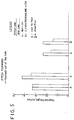
- a number of pitch compositions were prepared both with and without a foaming agent according to the present invention.
- the foaming agents employed were either nitrated decant oil (NDO) or 2, 4-dinitroanoline the particular amount of the foaming agent used being the same in all cases, i.e. 5 wt.%.
- Pitch compositions were also prepared in each group containing about 25 wt.% coke particles having a particle size 55% minus 0.074 mm (200 mesh).
- a number of holes were drilled into a graphite block, the diameter and depth of each hole being identical, i.e. 1,27 cm (1/2 inch) diameter and 11,4 cm (4 1/2 inches) deep.
- the same weight of each pitch composition i.e.
Landscapes
- Physics & Mathematics (AREA)
- Engineering & Computer Science (AREA)
- Plasma & Fusion (AREA)
- Discharge Heating (AREA)
- Conductive Materials (AREA)
- Other Surface Treatments For Metallic Materials (AREA)
- Prevention Of Electric Corrosion (AREA)
- Adhesives Or Adhesive Processes (AREA)
- Secondary Cells (AREA)
- Battery Electrode And Active Subsutance (AREA)
Claims (6)
- Elektrodenansatzstück zur Verbindung zweier Elektrodenteile eines Lichtbogenofens mit einem darin gebildeten Aufnahmeraum, der mit einem Gewindeteil an seiner Oberfläche in Verbindung steht, und ein elektrisch leitfähiges, zementartiges Bindemittel aufweist, welches in dem Aufnahmeraum zur Überführung zu dem Gewindeteil während der Verwendung des Elektrodenansatzstücks eingelagert ist, wobei das zementartige Bindemittel einen Hauptanteil Pech und einen geringeren Anteil eines schaumbildenden Mittels umfaßt, dadurch gekennzeichnet, daß das schaumbildende Mittel aus der Gruppe ausgewählt ist, die aus nitriertem Dekantöl, 2,4-Dinitroanilin und deren Gemischen besteht.
- Elektrodenansatzstück nach Anspruch 1 dadurch gekennzeichnet, daß das zementartige Bindemittel Kohlenteerpechpartikeln mit einem Erweichungspunkt von 75 bis 200° C enthält.
- Elektrodenansatzstück nach einem der Ansprüche 1 oder 2, dadurch gekennzeichnet, daß das zementartige Bindemittel 1 bis 20 Gew.% relativ grober Koks-, Kohlenstoff- oder Graphitpartikel enthält.
- Elektrodenansatzstück nach einem der Ansprüche 1 bis 3, dadurch gekennzeichnet, daß das zementartige Bindemittel zu einem Pfropfen geschmolzen ist.
- Elektrodenansatzstück nach einem der Ansprüche 1 bis 4, dadurch gekennzeichnet, daß sich das zementartige Bindemittel in einer Röhre befindet.
- Elektrode eines Uchtbogenofens, dadurch gekennzeichnet, daß diese Elektrode zwei Elektrodenteile enthält, die durch ein in einem der Ansprüche 1 bis 5 definiertes Elektrodenansatzstück miteinander verbunden sind.
Priority Applications (1)
| Application Number | Priority Date | Filing Date | Title |
|---|---|---|---|
| AT87112798T ATE70401T1 (de) | 1986-09-05 | 1987-09-02 | Elektrodenverbindung. |
Applications Claiming Priority (2)
| Application Number | Priority Date | Filing Date | Title |
|---|---|---|---|
| US06/904,067 US4725161A (en) | 1986-09-05 | 1986-09-05 | Electrode joint |
| US904067 | 2001-07-11 |
Publications (3)
| Publication Number | Publication Date |
|---|---|
| EP0260529A1 EP0260529A1 (de) | 1988-03-23 |
| EP0260529B1 EP0260529B1 (de) | 1991-12-11 |
| EP0260529B2 true EP0260529B2 (de) | 1998-01-28 |
Family
ID=25418486
Family Applications (1)
| Application Number | Title | Priority Date | Filing Date |
|---|---|---|---|
| EP87112798A Expired - Lifetime EP0260529B2 (de) | 1986-09-05 | 1987-09-02 | Elektrodenverbindung |
Country Status (6)
| Country | Link |
|---|---|
| US (1) | US4725161A (de) |
| EP (1) | EP0260529B2 (de) |
| JP (1) | JPH07111910B2 (de) |
| AT (1) | ATE70401T1 (de) |
| DE (1) | DE3775151D1 (de) |
| ES (1) | ES2027268T5 (de) |
Families Citing this family (14)
| Publication number | Priority date | Publication date | Assignee | Title |
|---|---|---|---|---|
| JP3181375B2 (ja) * | 1992-05-30 | 2001-07-03 | 株式会社豊夢 | 接合具及びそれを用いた構造部材の接合方法並びに構造部材間の接合構造 |
| FR2692748B1 (fr) * | 1992-06-18 | 1998-07-17 | Savoie Electrodes Refract | Joint de raccordement d'electrodes de four electrique. |
| RU2107413C1 (ru) * | 1993-06-17 | 1998-03-20 | СГЛ Карбон С.А. | Стыковое соединение электродов дуговой электропечи |
| FR2724219B1 (fr) * | 1994-09-05 | 1996-10-25 | Pechiney Electrometallurgie | Dispositif de montage d'une electrode composite a autocuisson pour four electrique a arc |
| US5575582A (en) * | 1995-01-18 | 1996-11-19 | Ucar Carbon Technology Corporation | Fastening device for securing electrode joints |
| BR9900252A (pt) | 1999-02-02 | 2000-08-29 | Companhia Brasileira Carbureto | Recipiente de aço inoxidável para a formação de eletrodos de autocozimento para a utilização em baixos-fornos elétricos de redução |
| BR9900253A (pt) | 1999-02-02 | 2000-08-29 | Companhia Brasileira Carbureto | Recipiente de alumìnio e aço inoxidável a formação de eletrodos de autocozimento para a utilização em baixos-fornos elétricos de redução |
| RU2226751C2 (ru) * | 2001-03-30 | 2004-04-10 | Хлопонин Виктор Николаевич | Способ периодического удлинения электрода электродуговой печи, электрод для его осуществления и способ предварительной подготовки электрода |
| US20020142164A1 (en) * | 2001-03-30 | 2002-10-03 | Pavlisin James Joseph | Pitch plug for carbon electrode joint assembly |
| KR100484598B1 (ko) * | 2001-12-31 | 2005-04-27 | 주식회사 동우 이앤씨 건축사사무소 | 합성수지 나선관 연결용 소켓과 그 제조방법 |
| US7230969B2 (en) * | 2004-06-03 | 2007-06-12 | Ucar Carbon Company Inc. | Electrode joint locking system |
| FR2866513B1 (fr) * | 2004-02-13 | 2006-08-04 | Sgl Carbon | Nipple pour electrode de four a arc |
| US20050207467A1 (en) * | 2004-03-18 | 2005-09-22 | John Montminy | Threaded pin for carbon electrodes, and electrode assembly with a threaded pin |
| DE102013216452B4 (de) * | 2013-08-20 | 2016-12-01 | Sgl Carbon Se | Verbesserte Elektroden/Nippel-Verbindung |
Family Cites Families (22)
| Publication number | Priority date | Publication date | Assignee | Title |
|---|---|---|---|---|
| US2093390A (en) * | 1934-12-19 | 1937-09-14 | Union Carbide & Carbon Corp | Means and method of making electrode joints |
| US2510230A (en) * | 1949-01-15 | 1950-06-06 | Union Carbide & Carbon Corp | Electrode joint |
| US2828162A (en) * | 1953-09-11 | 1958-03-25 | Union Carbide Corp | Furnace-electrode joint |
| US2826806A (en) * | 1953-10-28 | 1958-03-18 | Lou Tatom | Cluster gear assembling tool |
| US2894776A (en) * | 1954-08-12 | 1959-07-14 | Union Carbide Corp | Electrode joint |
| NL96582C (de) * | 1954-10-12 | 1900-01-01 | ||
| BE555170A (de) * | 1956-02-23 | 1900-01-01 | ||
| US2941828A (en) * | 1957-09-27 | 1960-06-21 | Speer Carbon Company | Electrode connecting nipple and joint |
| LU37186A1 (de) * | 1958-07-25 | |||
| US2941829A (en) * | 1958-08-25 | 1960-06-21 | Speer Carbon Company | Electrode connecting nipple and method |
| NL132919C (de) * | 1959-04-30 | 1900-01-01 | ||
| US3048434A (en) * | 1959-07-27 | 1962-08-07 | Union Carbide Corp | Electrode joint |
| US3353978A (en) * | 1964-08-14 | 1967-11-21 | United States Steel Corp | Self-extinguishing pitch foams |
| JPS4323517Y1 (de) * | 1964-12-29 | 1968-10-03 | ||
| US3567807A (en) * | 1967-05-19 | 1971-03-02 | Owens Corning Fiberglass Corp | Method of forming and carbonizing a composite article of inorganic particles bonded with foamed phenol formaldehyde resin |
| US3540764A (en) * | 1968-03-14 | 1970-11-17 | Union Carbide Corp | Resilient spacer for electrode joints |
| US3858994A (en) * | 1971-09-27 | 1975-01-07 | Carborundum Co | Electrode nipple drilling machine and process |
| US3705947A (en) * | 1971-10-18 | 1972-12-12 | John A Persson | Joining of prebaked electrodes |
| US3884840A (en) * | 1972-04-27 | 1975-05-20 | British Steel Corp | Graphite-pitch electrode paste |
| CA985457A (en) * | 1972-10-31 | 1976-03-16 | Rudolph W. Wallouch | Locking pitch for pitch reservoir nipples and method for use thereof |
| US4007324A (en) * | 1974-10-03 | 1977-02-08 | Airco, Inc. | Nipple for electrode joint |
| JPS5724456Y2 (de) * | 1977-09-09 | 1982-05-27 |
-
1986
- 1986-09-05 US US06/904,067 patent/US4725161A/en not_active Expired - Lifetime
-
1987
- 1987-09-02 AT AT87112798T patent/ATE70401T1/de not_active IP Right Cessation
- 1987-09-02 ES ES87112798T patent/ES2027268T5/es not_active Expired - Lifetime
- 1987-09-02 DE DE8787112798T patent/DE3775151D1/de not_active Expired - Lifetime
- 1987-09-02 EP EP87112798A patent/EP0260529B2/de not_active Expired - Lifetime
- 1987-09-04 JP JP62220566A patent/JPH07111910B2/ja not_active Expired - Lifetime
Also Published As
| Publication number | Publication date |
|---|---|
| EP0260529A1 (de) | 1988-03-23 |
| EP0260529B1 (de) | 1991-12-11 |
| ES2027268T3 (es) | 1992-06-01 |
| ES2027268T5 (es) | 1998-04-01 |
| US4725161A (en) | 1988-02-16 |
| DE3775151D1 (de) | 1992-01-23 |
| JPS63141292A (ja) | 1988-06-13 |
| ATE70401T1 (de) | 1991-12-15 |
| JPH07111910B2 (ja) | 1995-11-29 |
Similar Documents
| Publication | Publication Date | Title |
|---|---|---|
| EP0260529B2 (de) | Elektrodenverbindung | |
| US2510230A (en) | Electrode joint | |
| US9313834B2 (en) | Electrode joint locking system | |
| US7301982B2 (en) | Male-female electrode joint | |
| US3055789A (en) | Process of joining carbon bodies | |
| US2810117A (en) | Electrode connecting nipple | |
| US4007324A (en) | Nipple for electrode joint | |
| US2862748A (en) | Joint for carbon electrodes | |
| AU658304B2 (en) | Connecting joint for electric furnace electrodes | |
| WO2002078945A1 (en) | Pitch plug for carbon electrode joint assembly | |
| US20050249261A1 (en) | Optimized graphite electrode pin configuration | |
| EP1565040B1 (de) | Nippel für Lichtbogenelektroden | |
| US4729689A (en) | Electrode member and process for the production thereof | |
| US3976496A (en) | Locking pitch for pitch reservoir nipples | |
| US2805879A (en) | Electrode joints | |
| US3717911A (en) | Method of making a nipple-electrode joint | |
| US3419296A (en) | Electrode connecting pin and assembly | |
| EP1389896B1 (de) | Verfahren zur periodischen verlängerung einer elektrode für einen elektrischen bogenofen und elektrode für einen elektrischen bogenofen | |
| US4813805A (en) | Joint for carbon electrodes | |
| US2941829A (en) | Electrode connecting nipple and method | |
| US714159A (en) | Tap-hole plug. | |
| US8165183B2 (en) | Joint design | |
| KR20260019312A (ko) | 전극봉용 코크스 조성물, 전극봉 및 이의 제조 방법 | |
| JPH06100428B2 (ja) | 電極接続部の接合材 | |
| PL119904B1 (en) | Sealing compound for graphite joints |
Legal Events
| Date | Code | Title | Description |
|---|---|---|---|
| PUAI | Public reference made under article 153(3) epc to a published international application that has entered the european phase |
Free format text: ORIGINAL CODE: 0009012 |
|
| AK | Designated contracting states |
Kind code of ref document: A1 Designated state(s): AT BE DE ES FR GB IT SE |
|
| 17P | Request for examination filed |
Effective date: 19880430 |
|
| 17Q | First examination report despatched |
Effective date: 19890921 |
|
| GRAA | (expected) grant |
Free format text: ORIGINAL CODE: 0009210 |
|
| ITF | It: translation for a ep patent filed | ||
| AK | Designated contracting states |
Kind code of ref document: B1 Designated state(s): AT BE DE ES FR GB IT SE |
|
| PG25 | Lapsed in a contracting state [announced via postgrant information from national office to epo] |
Ref country code: SE Effective date: 19911211 |
|
| REF | Corresponds to: |
Ref document number: 70401 Country of ref document: AT Date of ref document: 19911215 Kind code of ref document: T |
|
| REF | Corresponds to: |
Ref document number: 3775151 Country of ref document: DE Date of ref document: 19920123 |
|
| ET | Fr: translation filed | ||
| REG | Reference to a national code |
Ref country code: ES Ref legal event code: FG2A Ref document number: 2027268 Country of ref document: ES Kind code of ref document: T3 |
|
| PLBI | Opposition filed |
Free format text: ORIGINAL CODE: 0009260 |
|
| 26 | Opposition filed |
Opponent name: PECHINEY, S.A., PARIS Effective date: 19920903 |
|
| PGFP | Annual fee paid to national office [announced via postgrant information from national office to epo] |
Ref country code: AT Payment date: 19960821 Year of fee payment: 10 |
|
| APAC | Appeal dossier modified |
Free format text: ORIGINAL CODE: EPIDOS NOAPO |
|
| APAC | Appeal dossier modified |
Free format text: ORIGINAL CODE: EPIDOS NOAPO |
|
| APAC | Appeal dossier modified |
Free format text: ORIGINAL CODE: EPIDOS NOAPO |
|
| PLAW | Interlocutory decision in opposition |
Free format text: ORIGINAL CODE: EPIDOS IDOP |
|
| PGFP | Annual fee paid to national office [announced via postgrant information from national office to epo] |
Ref country code: FR Payment date: 19970820 Year of fee payment: 11 |
|
| PGFP | Annual fee paid to national office [announced via postgrant information from national office to epo] |
Ref country code: DE Payment date: 19970822 Year of fee payment: 11 |
|
| PGFP | Annual fee paid to national office [announced via postgrant information from national office to epo] |
Ref country code: GB Payment date: 19970826 Year of fee payment: 11 |
|
| PG25 | Lapsed in a contracting state [announced via postgrant information from national office to epo] |
Ref country code: AT Free format text: LAPSE BECAUSE OF NON-PAYMENT OF DUE FEES Effective date: 19970902 |
|
| PGFP | Annual fee paid to national office [announced via postgrant information from national office to epo] |
Ref country code: BE Payment date: 19970909 Year of fee payment: 11 |
|
| PGFP | Annual fee paid to national office [announced via postgrant information from national office to epo] |
Ref country code: ES Payment date: 19970917 Year of fee payment: 11 |
|
| PUAH | Patent maintained in amended form |
Free format text: ORIGINAL CODE: 0009272 |
|
| STAA | Information on the status of an ep patent application or granted ep patent |
Free format text: STATUS: PATENT MAINTAINED AS AMENDED |
|
| ITF | It: translation for a ep patent filed | ||
| 27A | Patent maintained in amended form |
Effective date: 19980128 |
|
| AK | Designated contracting states |
Kind code of ref document: B2 Designated state(s): AT BE DE ES FR GB IT SE |
|
| REG | Reference to a national code |
Ref country code: ES Ref legal event code: DC2A Kind code of ref document: T5 Effective date: 19980306 |
|
| ET3 | Fr: translation filed ** decision concerning opposition | ||
| PG25 | Lapsed in a contracting state [announced via postgrant information from national office to epo] |
Ref country code: GB Free format text: LAPSE BECAUSE OF NON-PAYMENT OF DUE FEES Effective date: 19980902 |
|
| PG25 | Lapsed in a contracting state [announced via postgrant information from national office to epo] |
Ref country code: ES Free format text: THE PATENT HAS BEEN ANNULLED BY A DECISION OF A NATIONAL AUTHORITY Effective date: 19980903 |
|
| PG25 | Lapsed in a contracting state [announced via postgrant information from national office to epo] |
Ref country code: BE Free format text: LAPSE BECAUSE OF NON-PAYMENT OF DUE FEES Effective date: 19980930 |
|
| BERE | Be: lapsed |
Owner name: UNION CARBIDE CORP. Effective date: 19980930 |
|
| GBPC | Gb: european patent ceased through non-payment of renewal fee |
Effective date: 19980902 |
|
| PG25 | Lapsed in a contracting state [announced via postgrant information from national office to epo] |
Ref country code: FR Free format text: LAPSE BECAUSE OF NON-PAYMENT OF DUE FEES Effective date: 19990531 |
|
| PG25 | Lapsed in a contracting state [announced via postgrant information from national office to epo] |
Ref country code: DE Free format text: LAPSE BECAUSE OF NON-PAYMENT OF DUE FEES Effective date: 19990701 |
|
| REG | Reference to a national code |
Ref country code: FR Ref legal event code: ST |
|
| REG | Reference to a national code |
Ref country code: ES Ref legal event code: FD2A Effective date: 20001204 |
|
| PG25 | Lapsed in a contracting state [announced via postgrant information from national office to epo] |
Ref country code: IT Free format text: LAPSE BECAUSE OF NON-PAYMENT OF DUE FEES;WARNING: LAPSES OF ITALIAN PATENTS WITH EFFECTIVE DATE BEFORE 2007 MAY HAVE OCCURRED AT ANY TIME BEFORE 2007. THE CORRECT EFFECTIVE DATE MAY BE DIFFERENT FROM THE ONE RECORDED. Effective date: 20050902 |
|
| APAH | Appeal reference modified |
Free format text: ORIGINAL CODE: EPIDOSCREFNO |