EP0260281B1 - Optische datenverarbeitungsanordnungen und verfahren zur matrizen-inversion, -multiplikation und -addition - Google Patents
Optische datenverarbeitungsanordnungen und verfahren zur matrizen-inversion, -multiplikation und -addition Download PDFInfo
- Publication number
- EP0260281B1 EP0260281B1 EP87901215A EP87901215A EP0260281B1 EP 0260281 B1 EP0260281 B1 EP 0260281B1 EP 87901215 A EP87901215 A EP 87901215A EP 87901215 A EP87901215 A EP 87901215A EP 0260281 B1 EP0260281 B1 EP 0260281B1
- Authority
- EP
- European Patent Office
- Prior art keywords
- array
- elements
- accumulator
- matrix
- modulator
- Prior art date
- Legal status (The legal status is an assumption and is not a legal conclusion. Google has not performed a legal analysis and makes no representation as to the accuracy of the status listed.)
- Expired
Links
Images


Classifications
-
- G—PHYSICS
- G06—COMPUTING; CALCULATING OR COUNTING
- G06E—OPTICAL COMPUTING DEVICES; COMPUTING DEVICES USING OTHER RADIATIONS WITH SIMILAR PROPERTIES
- G06E3/00—Devices not provided for in group G06E1/00, e.g. for processing analogue or hybrid data
- G06E3/001—Analogue devices in which mathematical operations are carried out with the aid of optical or electro-optical elements
- G06E3/005—Analogue devices in which mathematical operations are carried out with the aid of optical or electro-optical elements using electro-optical or opto-electronic means
Definitions
- the present invention generally relates to an optical computing and data processing system according to claim 1 or 2 and a method for this, according to claim 3 or 4.
- the present invention relates to multistage lensless optical data processors capable of matrix inversion.
- Images, or other spatially relatable data may be treated as matrices composed of raster or vector scans of data elements that, at their real or effective resolution limit, are generally referred to as pixels.
- An ordinary image is typified by an analog picture frame taken as a cross section of an optical beam formed of a continuous series of such images. Each analog image frame typically contains an effectively continuous spatially distributed array of pixel data.
- discrete matrix data may be impressed onto a data beam by spatially modulating the cross section of a data beam in terms of, for example, either its localized intensity or polarization vector.
- optical processing is of great potential value due to its fundamentally parallel processing nature.
- the parallelism arises due to the processing of complete images at a time.
- the volume of data processed in parallel is generally equivalent to the effective resolution of the image.
- optical processing has the virtue of processing data in the same format that it is conventionally obtained.
- the data to be processed is generally obtained as a single image or as a raster scan of an image frame.
- an optical processor may receive data directly without conventional or other intermediate processing. Since the informative value of image data increases with the effective resolution of the image and the number of images considered, the particular and unique attributes of optical processing become quite desireable.
- a temporally variable mask for optical processors has been realized as a one-dimensional spatial light modulator (SLM) that, through electronic activation, effects selective alteration of the spatially distributed data impressed on a data beam by the mask.
- SLM spatial light modulator
- a typical SLM is in the form of a solid electro-optical element activated by a spatially distributed array of electrodes. The modulating image is effectively formed by separately establishing the voltage potential of each of the electrodes at an analog voltage corresponding to the respective intended data values.
- the present invention provides and optical data processor for processing four NxN matrices A, B, C and D to calculate the expression CA ⁇ 1B+D, where A ⁇ 1 signifies the inverse of A.
- the processor includes a first modulator for spatially modulating an optical beam in response to a signal representing a first number, and having a first set of modulation areas arranged as 2N-1 rows.
- a second modulator is provided for spatially modulating the optical beam exiting the first modulator in response to signals representing elements in a second row of 2N-1 numbers, and has a second set of modulation areas arranged as 2N-1 columns.
- a third modulator spatially modulates the optical beam exiting the second modulator in response to signals representing elements in a third column of 2N-1 numbers, and has a third set of modulation areas arranged as 2N-1 rows.
- a light detector is included having (2N-1)2 light detection areas arranged as a matrix array of 2N-1 rows and 2N-1 columns, where the detection areas provide an array of detector signals in response to light modulated by respective modulation areas of the first, second and third modulators.
- Each element in the array of detector signals being proportional, respectively, to the product of the first number, a respective element in the second row of numbers, and a respective element in the third column of numbers.
- An accumulator is provided for storing, adding, and shifting the array of detector signals, and has (2N)2 locations arranged as an accumulator matrix array of 2N rows and 2N columns.
- the elements of the matrix A are stored in the upper left quadrant of the accumulator array; the elements of the matrix B in the upper right quadrant; the elements of the matrix D in the lower right quadrant; and the polarity inverted elements of the matrix C in the lower left quadrant of the accumulator array.
- the optical processor further includes control circuitry for:
- the invention can be utilized to perform matrix inversion, multiplication, addition, or combinations of the above.
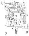
- the generalized system embodiment for use with the present invention is shown in Figure 1.
- the preferred multistage optical data processor ODP
- ODP optical data processor
- microcontroller 12 is operatively supported by a microcontroller 12 and interface registers 18, 22, 24, 26, 30, 32 and 34.
- the principal operative components of the ODP are shown in Figure 1 as including a flat panel or LED light source 14, matrix array accumulator 16 (also referred to as a detector array), and a plurality of spatial light modulators (SLMs) 36, 38, 40, 42, 44 and 46.
- SLMs spatial light modulators
- the light source 14, accumulator 16 and the SLMs 36, 38, 40, 42, 44, 46 are provided in closely adjacent parallel planes with respect to one another such that a relatively uniform beam sourced by the light source 14 travels through each of the spatial light modulators in succession and is ultimately received by the accumulator 16.
- the light beam is effectively used as a data transport mechanism acquiring data provided by each of the spatial light modulators that is subsequently delivered to the accumulator 16.
- the operation of each of the spatial light modulators can be explained in terms of their spatial transmissivity variation with respect to corresponding spatially distributed activating voltage potentials.
- the light amplitude transmissivity of a spatial light modulator is directly proportional to the applied voltage potential.
- the combined transmissivity (TO) of two serially coupled spatial light modulators is proportional to the product of the respective transmissivities T1, T2 of the spatial light modulators.
- V1 and V2 are the respectively applied voltage potentials
- C and D are the transmissivity to applied voltage coefficients for the respective spatial light modulators.
- the combined transmissivity T0 of the multistage spatial light modulator stack is proportional to the product of the respective transmissivities of the individual spatial light modulators.
- a light beam sourced by the flat panel 14 can thus be directed to acquire spatially distributed data corresponding to the spatially distributed relative transmissivities of each of the spatial light modulators 36, 38, 40, 42, 44 and 46.
- spatially relatable data is provided to the spatial light modulators 36, 38, 40, 42, 44 and 46 via the interface registers 22, 24, 26, 30, 32 and 34.
- These registers preferably provide high speed data storage and signal conditioning. They may also include arithmetic processors to perform functions such as numerical inversion.
- the stack of spatial light modulators preferably includes a plurality of one-dimensional spatial light modulators. As shown in Figure 1, one-dimensional spatial light modulators 36, 38, 40, 42, 44 and 46 are coupled to respective registers 22, 30, 24, 32 and 26 via interface data lines 60, 78, 62, 80, 64 and 82.
- the interface registers 22, 24, 26, 30, 32 and 34 in turn preferably receive data in a parallel form from the accumulator 16 via busses 77 and 79.
- the microcontroller 12 via the processor control buses 50, 70 provides the control signals. While the processor control buses 50, 70 are shown as separate and respectively connected to the registers by the register control lines 52, 54, 56, 72, 74 and 76, the interface registers may alternately be coupled via control multiplexers to a single, common control bus driven by the microcontroller 12. In either case, however, it is essential only that the microcontroller 12 possess sufficient control over the registers 22, 24, 26, 30, 32 and 34 to selectively provide its predetermined data thereto.
- the optical data processor system 10 is completed with the provision of the output register 18 coupled between the accumulator 16 and the controller 12.
- the accumulator 16 itself may be included as part of a matrix array of photosensitive devices 17 capable of converting incident light intensity into a corresponding voltage potential (or electrical charge) representative of the data beam at an array resolution at least matching that of the spatial light modulators 36, 38, 40, 42, 44 and 46.
- the accumulator 16 may be separate from the detector array 17.
- the accumulator 16 accumulates light beam data that can then be shifted by means of a clock signal supplied by a clock generator 83 to the data output register 18 via the output interface bus 88.
- the accumulator 16 also includes circular shift bus 86 and lateral shift bus 84 to permit a wide variety of storage, shift and subtraction operations to be performed within the accumulator 16 during the operation of the optical data processor 20.
- the data output register 18 is preferably a high speed analog-to-digital converter, shift register and buffer that channels the shifted output data from the accumulator 16 to the processor via the data bus 89.
- Initializing data from the controller 12 may be stored in the accumulator 16 via data line 87 and digital-to-analog converter 85.
- the microcontroller 12 possesses full control over the optical data processor 20.
- Any desired data can be provided to any specific combinaton of spatial light modulators to implement a desired data processing algorithm.
- Spatial light modulators within the optical data processor 20 may be provided with appropriate data via their respective data registers to uniformly maintain the spatial light modulators at their maximum transmissivity. Consequently, selected spatial light modulators may be effectively removed from the optical data processor by their appropriate data programming.
- the optical data processing system 10 provides an extremely flexible environment for the performance of optical data processing computations.
- optical data processor 20 fabricated in accordance with the preferred optical processor embodiment of the present invention is shown in Figure 2.
- the embodiment shown is exemplary as including substantially all of the principle components that may be incorporated into any preferred embodiment of the optical processor.
- the components of the optical data processor include the light source 14, SLM stages 36 through 46 and detector array 16.
- the flat panel light source 14 is preferably an electroluminescent display panel, or alternately, a gas plasma display panel or LED or LED array or laser diode or laser diode array.
- a diffuser (not shown) may be utilized to grade the light produced by the flat display panel into a spatially uniform optical beam.
- the bulk of the optical data processor 20 is formed by a serial stack of SLM stages, of which SLM stage 46 is representative.
- the SLM is a rigid structure required no additional support.
- the SLMs may be placed immediately adjacent one another, separated only by a thin insulating optically transparent layer, yielding an optimally compact multistage stack of spatial light modulators.
- polarizers 64 are preferably interposed between the SLMs. The polarizer 64 further permits the utilization of an unpolarized optical data beam source 14 in local polarization vector data representation embodiments of the present invention. If the principle of operation of the spatial light modulators is light absorption (instead of polarization rotation), then there is no need for the polarizers.
- the accumulator 16 is preferably included as part of a solid state matrix array of optical detectors 17.
- the optical detector array 17 is preferably a shift register array of conventional charge couple devices (CCDs) provided at an array density equivalent to the effective resolution of the optical data processor 20.
- CCDs charge couple devices
- the use of a CCD array is preferred both for its charge accumulation, i.e. data summing, capability as well as for the ease of fabricating CCD shift register circuitry that can be directly controlled by the microcontroller 12. Further the use of the CCD array permits substantial flexibility in the operation of the accumulator 16 by permitting data shifted out of the accumulator 16 and onto the data return bus 88 to be cycled back into the accumulator 16 via the circular shift data bus 86.
- the accumulator 16 possesses the desirable flexibility through the use of adjacent register propagation path interconnections to permit lateral cycling of the data contained therein via the lateral shift data bus 84 as indicated in Figure 1. Consequently, the accumulator 16 can be effectively utilized in the execution of quite complex optical data processing algorithms involving shift and sum operations under the direct control of the microcontroller 12.
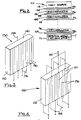
- the spatial light modulator 130 shown in Figure 3 includes an electro-optic element 132 preferably having two major parallel opposing surfaces upon which stripe electrodes 136 and potential reference plane 140 are provided, respectively.
- the electro-optic element 132 may be a transmission mode liquid crystal light valve though preferably it is a solid state electro-optic material, such as KD2P04 or BaTi03. This latter material polarization modulates light locally in proportion to the longitudinal and transverse voltage potential applied across the portion of the material that the light passes through.
- This material characteristically possesses sufficient structural strength to be adequately self-supporting for purposes of the present invention when utilized as electro-optic elements 132 and may be provided at a thickness of approximately 5 to 10 mils for a major suface area of approximately one square inch.
- the electrodes 136, 140 are preferably of a high conductivity transparent material such as indium tin oxide. Contact to the electrodes 136, 140 is preferably accomplished through the use of separate electrode leads 134, 138, respectively, that are attached using conventional wire bonding or solder bump interconnect technology.
- Figure 4 illustrates an alternate one-dimensional spatial light modulator.
- This spatial light modulator differs from that of Figure 3 by the relative placement of the signal 156 and potential reference 158 electrodes on the two major surfaces of the electro-optic element 152.
- a reference potential electrode 158 is interposed between pairs of the signal electrodes 156 to form an interdigitated electrode structure that is essentially identical on both major surfaces of the electro-optic element 152.
- the active portions of the electro-optic element 152 lie between each of the signal electrodes 156 and their surface neighboring refernce potential electrodes 158.
- the achievable electro-optic effect is enhanced through the utilization of both surfaces of the electro-optic element 152.
- all of the electrodes 156, 158 may be of an opaque conductive material, such as aluminum, that may be further advantageously utilized to effectively mask the active regions of the electro-optic element 152. That is, the electrodes 156, 158 may be utilized to block the respective pixel edge portions of the data beam as they diverge while passing through the electro-optic element 152.
- the electro-optic element 152 may be either a liquid crystal light valve or a solid state electro-optic material.
- transverse field polarization modulator electro-optic materials such as represented by LiNb03, LiTa03, BaTi03, Sr x Ba (1-x) Nd03 and PLZT are preferred.
- C BA
- C can also be written as a sum of matrices, each of which is the outer product between a column vector of B and the corresponding row vector of A.
- the principle behind an outer product matrix multiplier is to sequentially provide the rows of matrix B into an SLM such as SLM 38 and the corresponding columns of matrix A into another SLM such as SLM 36 which is orthogonal to the first SLM.
- the transmission of the two crossed SLMs during the nth clock cycle of clock generator 83 is given by the outer product of the nth row of B and the nth column of A.
- the transmitted light falls on accumulator detector array 16 and is summed to form the product matrix C.
- the multiplication of two NxN matrices, which requires N3 multiplications, is performed in N clock cycles.
- FIG. 5 shows the elements of the two matrices A and B as they are provided by storage registers 30 and 22 to SLMs 38 and 36, one row and column at a time, respectively.
- the electrodes on each SLM 36, 38 divide the SLM into strip shaped regions 92, 94, hereinafter referred to as unit cells. Each cell is used to process a matrix element.
- light from source 14 is modulated in one direction by the nth row of A and in the orthogonal direction by the nth column of B, forming the nth outer product matrix at the accumulator detector array 16, 17, the sum of which is the product matrix C. Note that only two SLMs are required for the matrix multiplication operation.
- the arry 16, 17 is divided into cells 96, where each cell corresponds to one of the elements c ij .
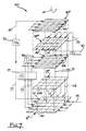
- Figure 6 shows an embodiment 100 of the invention which is an optical processor for processing four N x N matrices A, B, C and D to calculate the expression CA ⁇ 1B+D.
- N is shown equal to 3 in Figure 6. It will become apparent to those skilled in the art from the following description that N may be set to any practical value in the present invention.
- the invention makes use of the Faddeev algorithm, as disclosed in the text "Computational Methods of Linear Algebra," V.N. Faddeeva, Dover Publications, 1959, pp.90-93.
- the algorithm provides a means of calculating the expression CA ⁇ 1B+D where A, B, C and D are N x N matrices. These four matrices are placed in a four quadrant field (which forms a 2N x 2N matrix) as follows:
- a new four quadrant field is constructed by multiplying matrix A by a matrix W, and adding the result to the third quadrant field -C.
- the matrix B is also multiplied by the matrix W, and the result added to the fourth quadrant field D.
- the new four quadrant field is as follows:
- the terms of a new matrix may be calculated, using Gaussian elimination, by applying the formula: Where X nm new is the desired term of the new matrix, and X nm old is the corresponding term of the original matrix (5).
- the processor 100 includes first, second and third SLMs 40′, 38′, and 36′, respectively, and a light source 14 arranged in a manner similar to that previously described.
- the SLM 40′ is divided into 2N-1 rows of stripe shaped unit cells 102
- the SLM 38′ is divided into 2N-1 columns of striped shaped unit cells 104 (orthogonal to the cells 102)
- the SLM 36′ is divided into 2N-1 rows of striped shaped unit cells 106 (orthogonal to the cells 104).
- a light detector 17′ is provided, which is divided into (2N-1)2 light detection areas 108 arranged as a matrix array of 2N-1 rows and 2N-1 columns.
- the detection areas 108 provide detector signals in response to light modulated by respective modulation areas of the modulators 40′, 38′, 36′.
- the physical correspondence between the modulation areas 102, 104 and 106 and the detection areas 108 may be clearly seen in Figure 6.
- the detector signals from the areas 108 are each provided (via, for example, lines 112) to a corresponding location 110 in accumulator 16′.
- the accumulator 16′ which may be integrated with the detector 17′ as a single device, contains a total of (2N)2 locations 110 arranged as a matrix of 2N rows and 2N columns.
- the (2N-1)2 unshaded locations 110 shown in Figure 6 correspond to the respective (2N-1)2 detector areas 108 of detector 17′.
- the shaded locations 110 represent an additional left column and top row of accumulator locations.
- the accumulator 16′ is used for storing, adding and shifting the detector signals. These signals are proportional to the product of the signals modulating the corresponding areas of the SLMs 40′, 38′, and 36′, as explained above.
- the signal appearing at the left uppermost location 110 of the accumulator 16′ is provided via bus 77 to register 24, where it is arithmetically inverted with a minus sign (-1/X) and then provided via bus 62 as the modulation signal to all 2N-1 modulation areas 102 of SLM 40′.
- the signals appearing at the remaining 2N-1 locations 110 in the left-most column of the array 16′ are provided, through register 22 (for suitable signal conditioning) as modulation signals to corresponding rows of modulation areas 106 of SLM 36′.
- the signals appearing at the 2N-1 left-most locations 110 along the top row of the array 16′ are provided through register 30 (for suitable signal conditioning) to corresponding columns of modulation areas 104 of SLM 38′.
- the operation of the processor 100 is as follows. Signals representing the elements of the four matrices A, B, C, D are provided, via bus 81, to the accumulator 16′, where they are stored in the following manner.
- the matrix A is stored in the upper left quadrant; the matrix B in the upper right quadrant; the matrix C (with element polarity inverted) in the lower left quadrant; and the matrix D in the lower right quadrant of the accumulator 16′.
- the reader will note the analogy between the matrix storage locations and the four quadrant field (5).
- the processor 100 can be made to perform a wide variety of mathematical computations without the need for changes in system configuration. If, however, it is only desired to perform matrix inversion, the processor 100 may be simplified. Such a simplification appears in Figure 7.
- the processor 120 is similar in construction to the processor 100, with the following differences.
- First, second and third SLMs 40 ⁇ , 38 ⁇ and 36 ⁇ , respectively, are each divided into N unit cells, 102, 104, 106, respectively, where the cells are oriented in the same manner as their counterparts in the processor 100.
- detector 17 ⁇ is divided into N2 detector areas 108 arranged as an NxN matrix.
- Accumulator 16 ⁇ contains (N+1)2 locations arranged as N+1 rows and N+1 columns.
- N2 locations 110 (shown unshaded) of the accumulator 16 ⁇ correspond to the N2 detection areas 108 and receive detector signals therefrom.
- the signal appearing at the left uppermost location 110 of the accumulator 16 ⁇ is provided via bus 77 to register 24 where it is arithmetically inverted with a minus sign and then provided via bus 62 as the modulation signal to all N modulation areas 102 of SLM 40 ⁇ .
- the N-1 signals appearing at the left column of the array 16 ⁇ between the top and bottom rows are applied through register 22 (for suitable signal conditioning) to the N-1 modulation areas 106 in the top row of SLM 36 ⁇ .
- the register 22 provides a signal representing the number -1 to the area 106 at the bottom row of the SLM 36 ⁇ .
- the signals appearing at the N-1 top row locations 110 or the array 16 ⁇ between the left and right-most columns are provided through register 30 (for suitable signal conditioning) to the N-1 left-most columns 104 of the SLM 38 ⁇ .
- the register 30 provides a signal representing the number 1 to the right-most column 104 of the SLM 38 ⁇ .
- the operation of the processor 120 is as follows. Signals representing the elements of a matrix A are provided, via bus 81, to the accumulator 16 ⁇ where they are stored in the unshaded locations 110, while maintaining the spatial relationship between elements.
- a partial pivoting procedure is provided in the event a zero signal appears at the upper left-most location 110 of the array 16 ⁇ .
Landscapes
- Physics & Mathematics (AREA)
- Engineering & Computer Science (AREA)
- Theoretical Computer Science (AREA)
- Mathematical Physics (AREA)
- Nonlinear Science (AREA)
- Optics & Photonics (AREA)
- General Physics & Mathematics (AREA)
- Optical Modulation, Optical Deflection, Nonlinear Optics, Optical Demodulation, Optical Logic Elements (AREA)
- Liquid Crystal (AREA)
- Optical Communication System (AREA)
Claims (4)
ersten Modulatorvorrichtungen (40, 40′) zum räumlichen Modulieren eines optischen Strahls in Antwort auf ein Signal, welches eine erste Nummer vertritt und mit einem ersten Satz von Modulationsbereichen (102), welche in 2N-1 Reihen angeordnet sind;
zweiten Modulatorvorrichtungen (38, 38′) zum räumlichen Modulieren des optischen Strahles, der aus den ersten Modulatorvorrichtungen (40, 40′) austritt in Antwort auf Signale, welche Elemente in einer zweiten Reihe von 2N-1 Nummern vertreten und mit einem zweiten Satz von Modulationsbereichen (104), welche als 2N-1 Spalten angeordnet sind;
dritten Modulatorvorrichtungen (36, 36′) zum räumlichen Modulieren des optischen Strahles, in der aus den zweiten Modulatorvorrichtungen (38, 38′) austritt in Antwort auf Signale, welche Elemente in einer dritten Spalte von 2N-1 Nummern vertreten und mit einem dritten Satz von Modulationsbereichen (106), welche als 2N-1 Reihen angeordnet sind;
Lichtdetektorvorrichtungen (17, 17′) mit (2N-1)² Lichtdetektionsbereichen (108), welche als Matrixfeld von 2N-1 Reihen und 2N-1 Spalten angeordnet sind, wobei die Detektionsbereiche (108) ein Feld von Detektorsignalen in Antwort auf von den jeweiligen Modulationsbereichen (102, 104, 106) der ersten (40, 40′), zweiten (38, 38′) und dritten (36, 36′) Modulatorvorrichtungen moduliertem Licht bereitstellen, wobei jedes Element in dem Feld der Detektorsignale proportional zu dem Produkt der ersten Nummer bzw. einem entsprechenden Element in der zweiten Reihe von Nummern und einem entsprechenden Element in der dritten Spalte von Nummern ist;
Sammelvorrichtungen (16, 16′) zum Speichern, Addieren und Verschieben des Feldes der Detektorsignale mit (2N)² Stellen (110), welche als Sammelmatrixfeld (16, 16′) von 2N Reihen und 2N Spalten angeordnet sind;
Vorrichtungen zum Speichern der Elemente der Matrize A in dem oberen linken Quadranten des Sammelfeldes (16, 16′), zum Speichern der Elemente der Matrize B in dem oberen rechten Quadranten des Sammelfeldes (16, 16′), zum Speichern der Elemente der Matrize D in dem unteren rechten Quadranten des Sammelfeldes (16, 16′) und zum Speichern der vorzeicheninvertierten Elemente der Matrize C in dem unteren linken Quadranten des Sammelfeldes (16, 16′); und
Steuervorrichtungen (22, 24, 26, 30, 32, 34) zum:
ersten Modulatorvorrichtungen (40, 40˝) zur räumlichen Modulation eines optischen Strahles in Antwort auf ein Signal, welches eine erste Nummer vertritt und mit einem ersten Satz von Modulationsbereichen (102), welche als N Reihen angeordnet sind;
zweiten Modulatorvorrichtungen (38, 38˝) zur räumlichen Modulation des optischen Strahles, der aus den ersten Modulationsvorrichtungen (40, 40˝) austritt und mit einem zweiten Satz von Modulationsbereichen (104), welche als N Spalten angeordnet sind, wobei die am weitesten rechts liegende Spalte Licht in Antwort auf ein konstantes Signal moduliert, welches die Nummer 1 vertritt und die verbleibenden N-1 Spalten Licht in Antwort auf Signale modulieren, welche Elemente in einer zweiten Reihe von N-1 Nummern vertreten;
dritten Modulatorvorrichtungen (36, 36˝) zum räumlichen Modulieren des optischen Strahles, der aus den zweiten Modulatorvorrichtungen (38, 38˝) austritt und mit einem dritten Satz von Modulationsbereichen (106), welche als N Reihen angeordnet sind, wobei die unterste Reihe Licht in Antwort auf ein konstantes Signal moduliert, welches die Nummer -1 vertritt und die verbleibenden N-1 Reihen Licht in Antwort auf Signale modulieren, welche Elemente in einer dritten Spalte von N-1 Nummern vertreten;
Lichtdetektorvorrichtungen (17, 17˝) mit N² Lichtdetektionsbereichen (108), welche als Matrixfeld von N Reihen und N Spalten angeordnet sind, wobei die Detektionsbereiche (108) ein Feld von Detektorsignalen in Antwort auf Licht bereitstellen, welches durch die jeweiligen Modulationsbereiche (102, 104, 106) der ersten (40, 40˝), zweiten (38, 38˝) und dritten (36, 36˝) Modulatorvorrichtungen moduliert wurde, wobei jedes Element in dem Feld von Detektorsignalen proportional zu dem Produkt der ersten Nummer bzw. der Nummer 1 oder einem entsprechenden Element in der zweiten Reihe der Nummern bzw. der Nummer -1 oder einem entsprechenden Element in der dritten Spalte von Nummern ist;
Sammelvorrichtungen (16, 16˝) zum Speichern, Addieren und Verschieben des Feldes von Detektorsignalen mit (N+1)² Stellen (110), welche als Sammelmatrixfeld von N+1 Reihen und N+1 Spalten angeordnet sind;
Vorrichtungen zum Speichern der Elemente der Matrize A in den N am weitesten rechts liegenden Spalten und in den N am weitesten unten liegenden Reihen des Sammelfeldes (16, 16˝); und
Steuervorrichtungen (22, 24, 26, 30, 32, 34) zum:
Applications Claiming Priority (2)
| Application Number | Priority Date | Filing Date | Title |
|---|---|---|---|
| US836675 | 1986-03-05 | ||
| US06/836,675 US4800519A (en) | 1986-03-05 | 1986-03-05 | Optical data processing systems and methods for matrix inversion, multiplication, and addition |
Publications (2)
| Publication Number | Publication Date |
|---|---|
| EP0260281A1 EP0260281A1 (de) | 1988-03-23 |
| EP0260281B1 true EP0260281B1 (de) | 1992-03-04 |
Family
ID=25272465
Family Applications (1)
| Application Number | Title | Priority Date | Filing Date |
|---|---|---|---|
| EP87901215A Expired EP0260281B1 (de) | 1986-03-05 | 1987-01-27 | Optische datenverarbeitungsanordnungen und verfahren zur matrizen-inversion, -multiplikation und -addition |
Country Status (6)
| Country | Link |
|---|---|
| US (1) | US4800519A (de) |
| EP (1) | EP0260281B1 (de) |
| JP (1) | JPH0668713B2 (de) |
| DE (1) | DE3777033D1 (de) |
| IL (1) | IL81473A0 (de) |
| WO (1) | WO1987005423A1 (de) |
Cited By (1)
| Publication number | Priority date | Publication date | Assignee | Title |
|---|---|---|---|---|
| CN102567283A (zh) * | 2011-12-08 | 2012-07-11 | 清华大学 | 一种利用gpu对小矩阵求逆的方法 |
Families Citing this family (15)
| Publication number | Priority date | Publication date | Assignee | Title |
|---|---|---|---|---|
| US4991111A (en) * | 1986-08-28 | 1991-02-05 | Hughes Aircraft Company | Real-time image processing system |
| US5063531A (en) * | 1988-08-26 | 1991-11-05 | Nec Corporation | Optical neural net trainable in rapid time |
| GB2228118A (en) * | 1989-02-07 | 1990-08-15 | British Aerospace | Optical processors |
| US5361328A (en) * | 1989-09-28 | 1994-11-01 | Ezel, Inc. | Data processing system using a neural network |
| JP2724374B2 (ja) * | 1989-10-11 | 1998-03-09 | 株式会社鷹山 | データ処理装置 |
| US5130563A (en) * | 1989-11-30 | 1992-07-14 | Washington Research Foundation | Optoelectronic sensory neural network |
| US5050117A (en) * | 1990-02-06 | 1991-09-17 | Wright State University | Spatial light rebroadcaster optical computing cells |
| US5185715A (en) * | 1990-03-30 | 1993-02-09 | Hughes Aircraft Company | Data processing systems and methods for linear programming |
| GB2245732A (en) * | 1990-06-29 | 1992-01-08 | Philips Electronic Associated | Optical data processing device |
| US5276771A (en) * | 1991-12-27 | 1994-01-04 | R & D Associates | Rapidly converging projective neural network |
| GB2265036B (en) * | 1992-03-10 | 1995-08-02 | Sharp Kk | Optical processor and neuromorphic processor |
| US5312513A (en) * | 1992-04-03 | 1994-05-17 | Texas Instruments Incorporated | Methods of forming multiple phase light modulators |
| AU1800395A (en) * | 1994-03-02 | 1995-09-18 | Matthias Budil | Optical vector multiplier for neural networks |
| US11586889B1 (en) * | 2019-12-13 | 2023-02-21 | Amazon Technologies, Inc. | Sensory perception accelerator |
| CN113051523B (zh) * | 2021-03-16 | 2023-02-24 | 深圳前海黑顿科技有限公司 | 一种用于快速计算矩阵乘法的光学装置 |
Family Cites Families (8)
| Publication number | Priority date | Publication date | Assignee | Title |
|---|---|---|---|---|
| US3989355A (en) * | 1975-01-21 | 1976-11-02 | Xerox Corporation | Electro-optic display system |
| US4569033A (en) * | 1983-06-14 | 1986-02-04 | The United States Of America As Represented By The Secretary Of The Navy | Optical matrix-matrix multiplier based on outer product decomposition |
| US4620293A (en) * | 1983-12-23 | 1986-10-28 | General Dynamics, Pomona Division | Optical matrix multiplier |
| US4603398A (en) * | 1984-02-17 | 1986-07-29 | The United States Of America As Represented By The Secretary Of The Navy | Matrix-matrix multiplication using an electrooptical systolic/engagement array processing architecture |
| JPS60216337A (ja) * | 1984-04-12 | 1985-10-29 | Canon Inc | デジタル並列光演算装置 |
| US4633427A (en) * | 1984-06-29 | 1986-12-30 | The United States Of America As Represented By The Secretary Of The Navy | Advanced cube processor |
| US4607344A (en) * | 1984-09-27 | 1986-08-19 | The United States Of America As Represented By The Secretary Of The Navy | Triple matrix product optical processors using combined time-and-space integration |
| WO1986005608A1 (en) * | 1985-03-18 | 1986-09-25 | Hughes Aircraft Company | Programmable methods of performing complex optical computations using data processing system |
-
1986
- 1986-03-05 US US06/836,675 patent/US4800519A/en not_active Expired - Fee Related
-
1987
- 1987-01-27 JP JP62501152A patent/JPH0668713B2/ja not_active Expired - Lifetime
- 1987-01-27 WO PCT/US1987/000149 patent/WO1987005423A1/en active IP Right Grant
- 1987-01-27 DE DE8787901215T patent/DE3777033D1/de not_active Expired - Fee Related
- 1987-01-27 EP EP87901215A patent/EP0260281B1/de not_active Expired
- 1987-02-04 IL IL81473A patent/IL81473A0/xx not_active IP Right Cessation
Cited By (2)
| Publication number | Priority date | Publication date | Assignee | Title |
|---|---|---|---|---|
| CN102567283A (zh) * | 2011-12-08 | 2012-07-11 | 清华大学 | 一种利用gpu对小矩阵求逆的方法 |
| CN102567283B (zh) * | 2011-12-08 | 2014-12-31 | 清华大学 | 一种利用gpu对小矩阵求逆的方法 |
Also Published As
| Publication number | Publication date |
|---|---|
| JPH0668713B2 (ja) | 1994-08-31 |
| EP0260281A1 (de) | 1988-03-23 |
| IL81473A0 (en) | 1987-09-16 |
| US4800519A (en) | 1989-01-24 |
| DE3777033D1 (de) | 1992-04-09 |
| JPS63502624A (ja) | 1988-09-29 |
| WO1987005423A1 (en) | 1987-09-11 |
Similar Documents
| Publication | Publication Date | Title |
|---|---|---|
| EP0260281B1 (de) | Optische datenverarbeitungsanordnungen und verfahren zur matrizen-inversion, -multiplikation und -addition | |
| US5185715A (en) | Data processing systems and methods for linear programming | |
| US4569033A (en) | Optical matrix-matrix multiplier based on outer product decomposition | |
| EP0579356B1 (de) | Optisches Gerät zur Informationsverarbeitung | |
| Schaefer et al. | Tse computers | |
| US4747069A (en) | Programmable multistage lensless optical data processing system | |
| EP0256033B1 (de) | Optische analoge datenverarbeitungsanordnungen zur behandlung von bipolaren und komplexen daten | |
| EP0399753B1 (de) | Neuronale Netzwerke | |
| US4764891A (en) | Programmable methods of performing complex optical computations using data processing system | |
| US5099448A (en) | Matrix-vector multiplication apparatus | |
| GB2233469A (en) | Spatial light modulators | |
| EP0215008B1 (de) | Programmierbares verfahren zur durchführung von komplexen optischen berechnungen mit einer datenverarbeitungsanordnung | |
| EP0215822B1 (de) | Programmierbare mehrstufige linsenlose optische datenverarbeitungsanordnung | |
| Athale et al. | Compact architectures for adaptive neural nets | |
| Naughton et al. | General purpose acousto-optic connectionist processor | |
| McAulay | Deformable mirror nearest neighbor optical digital computer | |
| Cao | Real-time electro-optical pattern recognition and optical computing | |
| JP2778176B2 (ja) | 光演算装置 | |
| Yu et al. | Digital-Optical Matrix Multiplication With Magneto-Optic Spatial Light Modulators | |
| Evans et al. | On acoustooptic cell planes to map an R and F algorithm using a 2-D systolic geometry | |
| Evans et al. | Optical'Dequeues' For A'R And F'Systolic LU-Factorization Of Tridiagonal Systems | |
| Yang et al. | Fully parallel optical matrix-matrix multiplier using spherical lens array | |
| Evtikhiev et al. | Methods of Design of Specialized Optoelectronic Processors Constructed as Hybrid Microcircuits for Realization of Neural Network Algorithms | |
| JPH0659764A (ja) | 光ニューロ演算素子 |
Legal Events
| Date | Code | Title | Description |
|---|---|---|---|
| PUAI | Public reference made under article 153(3) epc to a published international application that has entered the european phase |
Free format text: ORIGINAL CODE: 0009012 |
|
| 17P | Request for examination filed |
Effective date: 19871104 |
|
| AK | Designated contracting states |
Kind code of ref document: A1 Designated state(s): DE FR GB IT NL |
|
| 17Q | First examination report despatched |
Effective date: 19900518 |
|
| GRAA | (expected) grant |
Free format text: ORIGINAL CODE: 0009210 |
|
| AK | Designated contracting states |
Kind code of ref document: B1 Designated state(s): DE FR GB IT NL |
|
| REF | Corresponds to: |
Ref document number: 3777033 Country of ref document: DE Date of ref document: 19920409 |
|
| ET | Fr: translation filed | ||
| ITF | It: translation for a ep patent filed |
Owner name: SOCIETA' ITALIANA BREVETTI S.P.A. |
|
| PLBE | No opposition filed within time limit |
Free format text: ORIGINAL CODE: 0009261 |
|
| STAA | Information on the status of an ep patent application or granted ep patent |
Free format text: STATUS: NO OPPOSITION FILED WITHIN TIME LIMIT |
|
| 26N | No opposition filed | ||
| PGFP | Annual fee paid to national office [announced via postgrant information from national office to epo] |
Ref country code: FR Payment date: 19931208 Year of fee payment: 8 |
|
| PGFP | Annual fee paid to national office [announced via postgrant information from national office to epo] |
Ref country code: GB Payment date: 19931210 Year of fee payment: 8 |
|
| PGFP | Annual fee paid to national office [announced via postgrant information from national office to epo] |
Ref country code: DE Payment date: 19931217 Year of fee payment: 8 |
|
| PGFP | Annual fee paid to national office [announced via postgrant information from national office to epo] |
Ref country code: NL Payment date: 19940131 Year of fee payment: 8 |
|
| PG25 | Lapsed in a contracting state [announced via postgrant information from national office to epo] |
Ref country code: GB Effective date: 19950127 |
|
| PG25 | Lapsed in a contracting state [announced via postgrant information from national office to epo] |
Ref country code: NL Effective date: 19950801 |
|
| GBPC | Gb: european patent ceased through non-payment of renewal fee |
Effective date: 19950127 |
|
| PG25 | Lapsed in a contracting state [announced via postgrant information from national office to epo] |
Ref country code: FR Effective date: 19950929 |
|
| NLV4 | Nl: lapsed or anulled due to non-payment of the annual fee |
Effective date: 19950801 |
|
| PG25 | Lapsed in a contracting state [announced via postgrant information from national office to epo] |
Ref country code: DE Effective date: 19951003 |
|
| REG | Reference to a national code |
Ref country code: FR Ref legal event code: ST |
|
| PG25 | Lapsed in a contracting state [announced via postgrant information from national office to epo] |
Ref country code: IT Free format text: LAPSE BECAUSE OF NON-PAYMENT OF DUE FEES;WARNING: LAPSES OF ITALIAN PATENTS WITH EFFECTIVE DATE BEFORE 2007 MAY HAVE OCCURRED AT ANY TIME BEFORE 2007. THE CORRECT EFFECTIVE DATE MAY BE DIFFERENT FROM THE ONE RECORDED. Effective date: 20050127 |