EP0260231B1 - Zylinderkarteneinheit, insbesondere zur Herstellung von nichtgewebten Textilien - Google Patents
Zylinderkarteneinheit, insbesondere zur Herstellung von nichtgewebten Textilien Download PDFInfo
- Publication number
- EP0260231B1 EP0260231B1 EP87830295A EP87830295A EP0260231B1 EP 0260231 B1 EP0260231 B1 EP 0260231B1 EP 87830295 A EP87830295 A EP 87830295A EP 87830295 A EP87830295 A EP 87830295A EP 0260231 B1 EP0260231 B1 EP 0260231B1
- Authority
- EP
- European Patent Office
- Prior art keywords
- drum
- fibres
- roll
- tile
- worker
- Prior art date
- Legal status (The legal status is an assumption and is not a legal conclusion. Google has not performed a legal analysis and makes no representation as to the accuracy of the status listed.)
- Expired - Lifetime
Links
- 238000009960 carding Methods 0.000 title claims abstract description 12
- 239000004753 textile Substances 0.000 title claims abstract description 5
- 238000011144 upstream manufacturing Methods 0.000 claims abstract description 15
- 238000004519 manufacturing process Methods 0.000 claims abstract description 3
- 238000009833 condensation Methods 0.000 claims description 8
- 230000005494 condensation Effects 0.000 claims description 8
- 229920002994 synthetic fiber Polymers 0.000 abstract description 2
- 230000002093 peripheral effect Effects 0.000 description 8
- 230000000694 effects Effects 0.000 description 5
- 241000347389 Serranus cabrilla Species 0.000 description 3
- 239000006185 dispersion Substances 0.000 description 2
- 239000000463 material Substances 0.000 description 2
- 230000035508 accumulation Effects 0.000 description 1
- 238000009825 accumulation Methods 0.000 description 1
- 230000002547 anomalous effect Effects 0.000 description 1
- 230000006835 compression Effects 0.000 description 1
- 238000007906 compression Methods 0.000 description 1
- 239000000835 fiber Substances 0.000 description 1
- 230000009931 harmful effect Effects 0.000 description 1
- 239000002184 metal Substances 0.000 description 1
- 238000000034 method Methods 0.000 description 1
Images

Classifications
-
- D—TEXTILES; PAPER
- D01—NATURAL OR MAN-MADE THREADS OR FIBRES; SPINNING
- D01G—PRELIMINARY TREATMENT OF FIBRES, e.g. FOR SPINNING
- D01G15/00—Carding machines or accessories; Card clothing; Burr-crushing or removing arrangements associated with carding or other preliminary-treatment machines
- D01G15/02—Carding machines
- D01G15/12—Details
- D01G15/14—Constructional features of carding elements, e.g. for facilitating attachment of card clothing
- D01G15/24—Flats or like members
Definitions
- the present invention relates to roll carding units in general, particularly for processing synthetic fibres for the production of non-woven textiles.
- the invention relates to a carding unit of the type comprising a high-speed rotary drum for drawing the fibre, a licker-in roll rotating tangentially to the input of the loader drum to load the fibres onto the surface thereof, a comber roll rotating tangentially to the output of the drum to load the fibres from the surface thereof by condensation, at least one worker roll rotating tangentially to the drum at a speed considerably less than the speed of the latter, between the licker-in and comber rolls to take up some of the fibres from the surface of the drum by condensation and to card these fibres, and auxiliary means for facilitating the loading of the fibres onto the or each worker roll and their removal therefrom.
- the auxiliary means are constituted by a clearer roll D rotating tangentially to the drum B and the corresponding worker roll C upstream of the zone T 1 in which the worker roll C and the drum B touch.
- the (or each) clearer roll D has a smaller diameter than that of the worker roll C which in its turn is smaller than that of the drum B, and a peripheral velocity greater than that of the worker roll C but less than that of the drum B.
- the points at which the clearer roll D and the worker roll C touch the drum B are indicated T 2 , T 3 respectively.
- the worker roll C which rotates in the opposite sense to the direction of advance F of the fibres and at a considerably lower speed than the drum B, loads the drum B by condensation of some of the fibres with which it is loaded. These fibres are combed and remain on the surface of the worker roll C.
- the points of the saw-toothed coverings of the lateral surfaces of the clearer roll D (which have vertices opposing the direction of advance F of the fibres and rotate in the opposite sense to the direction of advance at a greater peripheral velocity than the worker roll C) remove all the fibres combed and collected by the worker roll C.
- the object of the present invention is to avoid these disadvantages and in particular to eliminate the clearer rolls D by replacing them with means for achieving the same effect with greater efficiency and without the disadvantages mentioned above.
- the invention provides a roll worker unit, particularly for non-woven textiles, of the type defined above, characterised in that the auxiliary means for facilitating the loading of the fibres onto the or each worker roll and their removal therefrom comprise first and second tile-shaped members extending parallel to and adjacent the surface of the drum upstream and downstream respectively of the position at which the or each worker roll touches the drum, relative to the sense of rotation of the latter, and in which the upstream tile-shaped member includes an output section extending close to the zone of touching in order to convey the flow of fibres thereto, and the downstream tile-shaped member includes an input section at an angle to the surface of the drum to connect it to the surface of the worker roll.
- the entire process of loading, carding and unloading the or each worker roll C occurs at the zone in which it touches the drum B.
- the output section of the tile-shaped member upstream of the zone of touching keeps the fibres on the surface of the drum B and, by using the pressure created within it, increases the compression of the fibres against the points of the coverings of the worker roll C during loading of the fibres.
- the input section of the tile-shaped member disposed downstream of the zone of touching prevents dispersion of the fibres and creates a low pressure by the Venturi effect, which sucks all the fibres from the surface of the worker roll C and prevents them from returning to the zone in which the worker roll C touches the drum B.
- the removal of the clearer roll D associated with the or each worker roll C dispenses with the limitations on the dimensions of the unit in view of an increase in the width of working, and eliminates the zones of air pressure loss between the or each worker roll C and the drum B which could disturb and amass the already combed fibres in a non-homogeneous manner.
- a further advantage of the invention lies in the fact that the highly-cracked fibres do not return to the zone of touching between the or each worker roll C and the drum B by travelling a reverse path to their direction of advance on the back of the worker roll C, but always proceed in the natural direction of advance.
- the upstream and downstream tile-shaped members have identical shapes and the input section and output section of each tile are connected by an elongate, curved intermediate section having a radius of curvature corresponding to that of the drum.
- the output section of each tile is bevelled, while the input section has a terminal portion at its free end which is bent at an angle to one side of the intermediate section.
- the tile-shaped members may be adjustable to vary their distances from the surface of the drum.
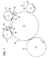
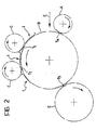
- These components include a drum B constituted by a rotating cylinder with a high peripheral velocity (400-1500 metres per minute) in the direction of advance F of the fibres and covered with saw-toothed coverings with the points facing in the direction of its sense of rotation.
- a drum B constituted by a rotating cylinder with a high peripheral velocity (400-1500 metres per minute) in the direction of advance F of the fibres and covered with saw-toothed coverings with the points facing in the direction of its sense of rotation.
- This has the task of bringing the fibres into contact with the various worker members described below and is supplied by a licker-in member A which may be constituted by a supply or opening roll arranged to control and meter the staple fibres or by a conveyor roll arranged to transfer the partially combed fibres from an upstream carding unit.
- the zone of touching T 4 between the licker-in member A and the drum B constitutes the input to this drum B, while its output is defined by the zone of touching T 5 between the drum B and a combing roll E disposed downstream of the worker members.
- This combing roll E has a diameter of about the same as that of the drum B and is rotated at a much lower peripheral velocity. It is covered with saw-toothed coverings the points of which face in the direction of advance of the fibres but it rotates in the opposite sense.
- the removal of the carded fibres from the drum B by the combing roll E occurs by condensation as a result of the considerable difference in peripheral velocities, with the aid of strong centrifugal forces resulting from the high speed of rotation of the drum B.
- each worker roll C is covered with saw-toothed coverings with points facing towards the direction of advance F of the fibres, while its motion is opposite this direction of advance. Thus, each worker roll C presents opposing points at the point of touching Ti with the drum B.
- each worker roll C by rotating in the opposite sense to the direction F of advance of the fibres and at a lower velocity than the drum B, is loaded with some of fibres with which the drum B is loaded by condensation at the zone of touching T 1 due to the conformation of the coverings. These fibres are combed and remain on the surface of the worker roll C.
- the carding unit uses a pair of tile-shaped members 1 disposed upstream and downstream respectively of the zone of touching T 1 between the worker roll C and the drum B, instead of the conventional clearer roll D.
- each tile 1 conveniently have identical forms and, as illustrated in greater detail in Figure 3, each comprise a cover of metal or other suitable material which extends parallel to and adjacent the surface of the drum B.
- each tile 1 has an initial section 2 and a finai section 3 connected together by an elongate intermediate section 4 having a curved shape with a radius of curvature corresponding to that of the drum B.
- the initial section 2 is substantially flat and forms an angle with the intermediate section 4 so as to diverge outwardly from the surface of the drum B.
- the free end of the initial section 2 has an end portion 5 which is bent at an angle to one side of the intermediate section 4.
- the final section 3 is constituted by a bevelled end of the intermediate portion 4.
- the one upstream of the zone of touching T 1 constitutes the input tile and the one downstream of the zone of touching T 1 constitutes the output tile, respectively.
- the input tile 1 of the left-hand worker roll C also constitutes the output tile of the right-hand worker roll C in the drawing, which is associated with the input tile 1 disposed upstream of the zone of touching T 1 between this right-hand worker roll and the drum B.
- the final section 3 of the upstream tile 1 extends so as to be close to the zone of touching Ti, while the initial section 2 of the downstream tile connects the lateral surface of the worker roll 5 to the lateral surface of the drum B.
- the fibres entrained by the drum B (or coming from a previous worker roll C) are conveyed to the zone of touching Ti across the upstream tile 1.
- This tile 1 keeps the fibres on the surface of the drum B and conveys the flow across the final section 3 to the exact point of touching T, avoiding loss of material.
- the combed fibres are then returned during rotation of the worker roll C towards the zone of touching Ti, where they are removed from the surface of the worker roll C and unloaded again onto the surface of the drum B.
- This unloading is achieved by virtue of the aerodynamic centrifugal expansion due to the peripheral velocity of the drum B in correspondence with the initial section 2 of the downstream tile 1.
- a low pressure is generated in practice by the Venturi effect, and tends to make the fibres adhere to the surface of the drum B.
- the intermediate section 4 of the downstream tile 1 sucks the fibres from the surface of the worker roll C to prevent their return to the point of touching T and avoid their dispersion.
- the distance of the tiles 1 from the surface of the drum B may be adjustable by means of simple devices, not illustrated, within the competence of an expert in the art, just as provision could be made for a variation in the relative angular position of the tile itself and the drum B.
Landscapes
- Engineering & Computer Science (AREA)
- Textile Engineering (AREA)
- Preliminary Treatment Of Fibers (AREA)
- Treatment Of Fiber Materials (AREA)
- Nonwoven Fabrics (AREA)
- Woven Fabrics (AREA)
Claims (5)
Priority Applications (1)
| Application Number | Priority Date | Filing Date | Title |
|---|---|---|---|
| AT87830295T ATE52283T1 (de) | 1986-09-10 | 1987-07-29 | Zylinderkarteneinheit, insbesondere zur herstellung von nichtgewebten textilien. |
Applications Claiming Priority (2)
| Application Number | Priority Date | Filing Date | Title |
|---|---|---|---|
| IT8667701A IT1215189B (it) | 1986-09-10 | 1986-09-10 | Gruppo cardante a cilindri partico larmente per la produzione di tessuti non tessuti |
| IT6770186 | 1986-09-10 |
Publications (2)
| Publication Number | Publication Date |
|---|---|
| EP0260231A1 EP0260231A1 (de) | 1988-03-16 |
| EP0260231B1 true EP0260231B1 (de) | 1990-04-25 |
Family
ID=11304617
Family Applications (1)
| Application Number | Title | Priority Date | Filing Date |
|---|---|---|---|
| EP87830295A Expired - Lifetime EP0260231B1 (de) | 1986-09-10 | 1987-07-29 | Zylinderkarteneinheit, insbesondere zur Herstellung von nichtgewebten Textilien |
Country Status (7)
| Country | Link |
|---|---|
| US (1) | US4817246A (de) |
| EP (1) | EP0260231B1 (de) |
| AT (1) | ATE52283T1 (de) |
| DE (1) | DE3762433D1 (de) |
| ES (1) | ES2014496B3 (de) |
| GR (1) | GR3000451T3 (de) |
| IT (1) | IT1215189B (de) |
Families Citing this family (5)
| Publication number | Priority date | Publication date | Assignee | Title |
|---|---|---|---|---|
| US5333357A (en) * | 1993-06-04 | 1994-08-02 | Duncan Richard N | Carding machine having a fine-fiber brush |
| AT402302B (de) * | 1994-07-19 | 1997-04-25 | Fehrer Ernst | Vorrichtung zum herstellen eines faservlieses |
| AT402303B (de) * | 1994-10-24 | 1997-04-25 | Fehrer Ernst | Vorrichtung zum herstellen eines faservlieses |
| US7416638B2 (en) * | 2003-11-18 | 2008-08-26 | Georgia-Pacific Consumer Products Lp | Apparatus and method for manufacturing a multi-layer web product |
| DE102005012251B4 (de) * | 2005-03-15 | 2019-05-09 | Trützschler GmbH & Co Kommanditgesellschaft | Vorrichtung an einer Karde zur Verarbeitung von Textilfasern, z. B. Baumwolle, Chemiefasern u. dgl. mit einer Trommel |
Family Cites Families (8)
| Publication number | Priority date | Publication date | Assignee | Title |
|---|---|---|---|---|
| BE396175A (de) * | ||||
| US2243685A (en) * | 1940-03-21 | 1941-05-27 | Celanese Corp | Carding machine |
| US2788547A (en) * | 1952-06-11 | 1957-04-16 | Stearns & Foster Company | Carding machine |
| CH501068A (de) * | 1967-11-20 | 1970-12-31 | S Jr Elliott Olin | Zusammengesetzte Kardenplatte |
| JPS4930008B1 (de) * | 1969-06-14 | 1974-08-09 | ||
| US3858276A (en) * | 1973-08-27 | 1975-01-07 | John D Hollingsworth | Apparatus for removing trash from carded fibers |
| ES211105Y (es) * | 1975-03-26 | 1976-10-16 | Barcons Estabanell | Un dispositivo peinador-limpiador perfeccionado para cardasuniversales. |
| EP0019455A1 (de) * | 1979-05-18 | 1980-11-26 | Carding Specialists (Canada) Limited | Karde und Verfahren zum Kardieren von Textilfasern |
-
1986
- 1986-09-10 IT IT8667701A patent/IT1215189B/it active
-
1987
- 1987-07-29 EP EP87830295A patent/EP0260231B1/de not_active Expired - Lifetime
- 1987-07-29 AT AT87830295T patent/ATE52283T1/de not_active IP Right Cessation
- 1987-07-29 ES ES87830295T patent/ES2014496B3/es not_active Expired - Lifetime
- 1987-07-29 DE DE8787830295T patent/DE3762433D1/de not_active Expired - Lifetime
- 1987-08-14 US US07/085,376 patent/US4817246A/en not_active Expired - Lifetime
-
1990
- 1990-04-26 GR GR90400201T patent/GR3000451T3/el unknown
Also Published As
| Publication number | Publication date |
|---|---|
| IT1215189B (it) | 1990-01-31 |
| IT8667701A0 (it) | 1986-09-10 |
| DE3762433D1 (de) | 1990-05-31 |
| ATE52283T1 (de) | 1990-05-15 |
| EP0260231A1 (de) | 1988-03-16 |
| US4817246A (en) | 1989-04-04 |
| ES2014496B3 (es) | 1990-07-16 |
| GR3000451T3 (en) | 1991-06-28 |
Similar Documents
| Publication | Publication Date | Title |
|---|---|---|
| US4279060A (en) | Method of and apparatus for the production of open non-woven fabric from fibrous material | |
| EP0260231B1 (de) | Zylinderkarteneinheit, insbesondere zur Herstellung von nichtgewebten Textilien | |
| US3066358A (en) | Fibrous web and methods and apparatus for producing the same | |
| EP0254694B1 (de) | Mehrfachkarde oder sogennante Tandemkarde mit Übertragungs-, Kardier- und Reinigungszylinder | |
| US3470586A (en) | Textile carding | |
| US4615080A (en) | Method and apparatus for making a web from staple fibers | |
| US2788547A (en) | Carding machine | |
| US3983273A (en) | Carding machines | |
| US4368561A (en) | Apparatus for stripping revolving card flats | |
| US4129924A (en) | Apparatus for separating card strips during carding of fibrous materials | |
| US4858276A (en) | Universal textile machine for optionally manufacturing longitudinally and/or randomly oriented fiber fleece | |
| EP0271677A3 (en) | Carding machine for making a fibre fleece | |
| EP1004693B1 (de) | Vorrichtung zum Vorbereiten und Oeffnen von Faserflocken geliefert zu einer Karde | |
| US2532330A (en) | Evener for cotton pickers | |
| EP0194850B1 (de) | Vorrichtung zur Herstellung von Holzpulpe enthaltenden Faservliesen | |
| US3946464A (en) | Devices for handling unspun fibers | |
| US2949645A (en) | Carding machine | |
| GB2367306A (en) | Separating blade system for spinning preparation machine | |
| JPH10505638A (ja) | カードおよび空気力学的に形成された繊維状ウェブの製造方法 | |
| US3538552A (en) | Carding device | |
| US6195842B1 (en) | Feeding carded fiber to an airlay | |
| KR850000721B1 (ko) | 카딩기로부터 나온 플리이스의 콘덴싱장치 | |
| US4553289A (en) | Apparatus for producing a wide fibrous web | |
| EP0250126A1 (de) | Karden | |
| US656403A (en) | Apparatus for carding wool. |
Legal Events
| Date | Code | Title | Description |
|---|---|---|---|
| PUAI | Public reference made under article 153(3) epc to a published international application that has entered the european phase |
Free format text: ORIGINAL CODE: 0009012 |
|
| AK | Designated contracting states |
Kind code of ref document: A1 Designated state(s): AT BE CH DE ES FR GB GR IT LI LU NL SE |
|
| 17P | Request for examination filed |
Effective date: 19880312 |
|
| 17Q | First examination report despatched |
Effective date: 19890629 |
|
| GRAA | (expected) grant |
Free format text: ORIGINAL CODE: 0009210 |
|
| AK | Designated contracting states |
Kind code of ref document: B1 Designated state(s): AT BE CH DE ES FR GB GR IT LI LU NL SE |
|
| REF | Corresponds to: |
Ref document number: 52283 Country of ref document: AT Date of ref document: 19900515 Kind code of ref document: T |
|
| ITF | It: translation for a ep patent filed | ||
| REF | Corresponds to: |
Ref document number: 3762433 Country of ref document: DE Date of ref document: 19900531 |
|
| ET | Fr: translation filed | ||
| REG | Reference to a national code |
Ref country code: GR Ref legal event code: FG4A Free format text: 3000451 |
|
| PLBE | No opposition filed within time limit |
Free format text: ORIGINAL CODE: 0009261 |
|
| STAA | Information on the status of an ep patent application or granted ep patent |
Free format text: STATUS: NO OPPOSITION FILED WITHIN TIME LIMIT |
|
| 26N | No opposition filed | ||
| ITTA | It: last paid annual fee | ||
| EPTA | Lu: last paid annual fee | ||
| EAL | Se: european patent in force in sweden |
Ref document number: 87830295.9 |
|
| REG | Reference to a national code |
Ref country code: GB Ref legal event code: IF02 |
|
| PGFP | Annual fee paid to national office [announced via postgrant information from national office to epo] |
Ref country code: SE Payment date: 20050531 Year of fee payment: 19 |
|
| PGFP | Annual fee paid to national office [announced via postgrant information from national office to epo] |
Ref country code: ES Payment date: 20050601 Year of fee payment: 19 |
|
| PGFP | Annual fee paid to national office [announced via postgrant information from national office to epo] |
Ref country code: AT Payment date: 20050609 Year of fee payment: 19 |
|
| PGFP | Annual fee paid to national office [announced via postgrant information from national office to epo] |
Ref country code: NL Payment date: 20050616 Year of fee payment: 19 |
|
| PGFP | Annual fee paid to national office [announced via postgrant information from national office to epo] |
Ref country code: LU Payment date: 20050627 Year of fee payment: 19 |
|
| PGFP | Annual fee paid to national office [announced via postgrant information from national office to epo] |
Ref country code: GR Payment date: 20050628 Year of fee payment: 19 Ref country code: BE Payment date: 20050628 Year of fee payment: 19 |
|
| PGFP | Annual fee paid to national office [announced via postgrant information from national office to epo] |
Ref country code: FR Payment date: 20050729 Year of fee payment: 19 |
|
| PG25 | Lapsed in a contracting state [announced via postgrant information from national office to epo] |
Ref country code: AT Free format text: LAPSE BECAUSE OF NON-PAYMENT OF DUE FEES Effective date: 20060729 |
|
| PG25 | Lapsed in a contracting state [announced via postgrant information from national office to epo] |
Ref country code: SE Free format text: LAPSE BECAUSE OF NON-PAYMENT OF DUE FEES Effective date: 20060730 |
|
| PG25 | Lapsed in a contracting state [announced via postgrant information from national office to epo] |
Ref country code: BE Free format text: LAPSE BECAUSE OF NON-PAYMENT OF DUE FEES Effective date: 20060731 |
|
| PGFP | Annual fee paid to national office [announced via postgrant information from national office to epo] |
Ref country code: IT Payment date: 20060731 Year of fee payment: 20 |
|
| PGFP | Annual fee paid to national office [announced via postgrant information from national office to epo] |
Ref country code: GB Payment date: 20060914 Year of fee payment: 20 |
|
| PGFP | Annual fee paid to national office [announced via postgrant information from national office to epo] |
Ref country code: CH Payment date: 20060918 Year of fee payment: 20 |
|
| PGFP | Annual fee paid to national office [announced via postgrant information from national office to epo] |
Ref country code: DE Payment date: 20060925 Year of fee payment: 20 |
|
| PG25 | Lapsed in a contracting state [announced via postgrant information from national office to epo] |
Ref country code: NL Free format text: LAPSE BECAUSE OF NON-PAYMENT OF DUE FEES Effective date: 20070201 |
|
| EUG | Se: european patent has lapsed | ||
| NLV4 | Nl: lapsed or anulled due to non-payment of the annual fee |
Effective date: 20070201 |
|
| REG | Reference to a national code |
Ref country code: FR Ref legal event code: ST Effective date: 20070330 |
|
| REG | Reference to a national code |
Ref country code: GB Ref legal event code: PE20 |
|
| REG | Reference to a national code |
Ref country code: CH Ref legal event code: PL |
|
| REG | Reference to a national code |
Ref country code: ES Ref legal event code: FD2A Effective date: 20060731 |
|
| PG25 | Lapsed in a contracting state [announced via postgrant information from national office to epo] |
Ref country code: GB Free format text: LAPSE BECAUSE OF EXPIRATION OF PROTECTION Effective date: 20070728 |
|
| BERE | Be: lapsed |
Owner name: FONDERIE OFFICINE RIUNITE *FOR ING. GRAZIANO DI L. Effective date: 20060731 |
|
| PG25 | Lapsed in a contracting state [announced via postgrant information from national office to epo] |
Ref country code: ES Free format text: LAPSE BECAUSE OF NON-PAYMENT OF DUE FEES Effective date: 20060731 |
|
| PG25 | Lapsed in a contracting state [announced via postgrant information from national office to epo] |
Ref country code: FR Free format text: LAPSE BECAUSE OF NON-PAYMENT OF DUE FEES Effective date: 20060731 |
|
| PG25 | Lapsed in a contracting state [announced via postgrant information from national office to epo] |
Ref country code: LU Free format text: LAPSE BECAUSE OF NON-PAYMENT OF DUE FEES Effective date: 20060729 |
|
| PG25 | Lapsed in a contracting state [announced via postgrant information from national office to epo] |
Ref country code: GR Free format text: LAPSE BECAUSE OF NON-PAYMENT OF DUE FEES Effective date: 20070202 |