EP0260080B1 - Instrument für das Einsetzen eines Injektionsreservoirs - Google Patents
Instrument für das Einsetzen eines Injektionsreservoirs Download PDFInfo
- Publication number
- EP0260080B1 EP0260080B1 EP87307848A EP87307848A EP0260080B1 EP 0260080 B1 EP0260080 B1 EP 0260080B1 EP 87307848 A EP87307848 A EP 87307848A EP 87307848 A EP87307848 A EP 87307848A EP 0260080 B1 EP0260080 B1 EP 0260080B1
- Authority
- EP
- European Patent Office
- Prior art keywords
- injection reservoir
- reservoir
- instrument
- injection
- tubing
- Prior art date
- Legal status (The legal status is an assumption and is not a legal conclusion. Google has not performed a legal analysis and makes no representation as to the accuracy of the status listed.)
- Expired - Lifetime
Links
- 238000002347 injection Methods 0.000 title claims description 80
- 239000007924 injection Substances 0.000 title claims description 80
- 238000007920 subcutaneous administration Methods 0.000 title claims description 17
- 238000003780 insertion Methods 0.000 title description 6
- 230000037431 insertion Effects 0.000 title description 6
- 239000012530 fluid Substances 0.000 claims description 7
- 230000013011 mating Effects 0.000 claims description 5
- 238000007789 sealing Methods 0.000 claims description 5
- 239000000203 mixture Substances 0.000 claims description 2
- 210000001519 tissue Anatomy 0.000 description 15
- 239000002775 capsule Substances 0.000 description 6
- 239000000463 material Substances 0.000 description 4
- 239000007943 implant Substances 0.000 description 2
- 239000002184 metal Substances 0.000 description 2
- 238000001356 surgical procedure Methods 0.000 description 2
- 230000015572 biosynthetic process Effects 0.000 description 1
- 230000000740 bleeding effect Effects 0.000 description 1
- 230000007812 deficiency Effects 0.000 description 1
- 238000002513 implantation Methods 0.000 description 1
- 238000000034 method Methods 0.000 description 1
- 238000012986 modification Methods 0.000 description 1
- 230000004048 modification Effects 0.000 description 1
- 210000000056 organ Anatomy 0.000 description 1
- 238000002559 palpation Methods 0.000 description 1
- 206010033675 panniculitis Diseases 0.000 description 1
- 229920002492 poly(sulfone) Polymers 0.000 description 1
- 229920002379 silicone rubber Polymers 0.000 description 1
- 229910001220 stainless steel Inorganic materials 0.000 description 1
- 239000010935 stainless steel Substances 0.000 description 1
- 238000010254 subcutaneous injection Methods 0.000 description 1
- 239000007929 subcutaneous injection Substances 0.000 description 1
- 210000004304 subcutaneous tissue Anatomy 0.000 description 1
Images
Classifications
-
- A—HUMAN NECESSITIES
- A61—MEDICAL OR VETERINARY SCIENCE; HYGIENE
- A61M—DEVICES FOR INTRODUCING MEDIA INTO, OR ONTO, THE BODY; DEVICES FOR TRANSDUCING BODY MEDIA OR FOR TAKING MEDIA FROM THE BODY; DEVICES FOR PRODUCING OR ENDING SLEEP OR STUPOR
- A61M39/00—Tubes, tube connectors, tube couplings, valves, access sites or the like, specially adapted for medical use
- A61M39/02—Access sites
- A61M39/0208—Subcutaneous access sites for injecting or removing fluids
-
- A—HUMAN NECESSITIES
- A61—MEDICAL OR VETERINARY SCIENCE; HYGIENE
- A61B—DIAGNOSIS; SURGERY; IDENTIFICATION
- A61B90/00—Instruments, implements or accessories specially adapted for surgery or diagnosis and not covered by any of the groups A61B1/00 - A61B50/00, e.g. for luxation treatment or for protecting wound edges
-
- A—HUMAN NECESSITIES
- A61—MEDICAL OR VETERINARY SCIENCE; HYGIENE
- A61F—FILTERS IMPLANTABLE INTO BLOOD VESSELS; PROSTHESES; DEVICES PROVIDING PATENCY TO, OR PREVENTING COLLAPSING OF, TUBULAR STRUCTURES OF THE BODY, e.g. STENTS; ORTHOPAEDIC, NURSING OR CONTRACEPTIVE DEVICES; FOMENTATION; TREATMENT OR PROTECTION OF EYES OR EARS; BANDAGES, DRESSINGS OR ABSORBENT PADS; FIRST-AID KITS
- A61F2/00—Filters implantable into blood vessels; Prostheses, i.e. artificial substitutes or replacements for parts of the body; Appliances for connecting them with the body; Devices providing patency to, or preventing collapsing of, tubular structures of the body, e.g. stents
- A61F2/02—Prostheses implantable into the body
- A61F2/12—Mammary prostheses
-
- A—HUMAN NECESSITIES
- A61—MEDICAL OR VETERINARY SCIENCE; HYGIENE
- A61B—DIAGNOSIS; SURGERY; IDENTIFICATION
- A61B17/00—Surgical instruments, devices or methods
- A61B17/00234—Surgical instruments, devices or methods for minimally invasive surgery
- A61B2017/00353—Surgical instruments, devices or methods for minimally invasive surgery one mechanical instrument performing multiple functions, e.g. cutting and grasping
-
- A—HUMAN NECESSITIES
- A61—MEDICAL OR VETERINARY SCIENCE; HYGIENE
- A61B—DIAGNOSIS; SURGERY; IDENTIFICATION
- A61B17/00—Surgical instruments, devices or methods
- A61B17/32—Surgical cutting instruments
- A61B2017/320056—Tunnelers
-
- A—HUMAN NECESSITIES
- A61—MEDICAL OR VETERINARY SCIENCE; HYGIENE
- A61M—DEVICES FOR INTRODUCING MEDIA INTO, OR ONTO, THE BODY; DEVICES FOR TRANSDUCING BODY MEDIA OR FOR TAKING MEDIA FROM THE BODY; DEVICES FOR PRODUCING OR ENDING SLEEP OR STUPOR
- A61M39/00—Tubes, tube connectors, tube couplings, valves, access sites or the like, specially adapted for medical use
- A61M39/02—Access sites
- A61M39/0208—Subcutaneous access sites for injecting or removing fluids
- A61M2039/0232—Subcutaneous access sites for injecting or removing fluids having means for facilitating the insertion into the body
Definitions
- This invention relates to a surgical instrument for the subcutaneous insertion and removal of an injection reservoir used for the inflation of an implantable prosthesis such as a tissue expander.
- Inflatable prostheses such as mammary prostheses and tissue expanders can be inflated subcutaneously by two commonly available means.
- the first means is via a resealable valve mounted directly on the surface of the prosthesis itself to permit introduction of a fluid into the prosthesis via a hypodermic syringe.
- the second means for inflating such a prosthesis is via an injection reservoir which is not itself expandable and has a self-sealing area designed to be punctured by a hypodermic needle to permit introduction of a fluid into the hollow center of the injection reservoir which then travels through an elongated fluid conduit such as a piece of tubing over to the inflatable prosthesis itself.
- Remotely placed injection reservoirs of the second type have also been referred to as "remote valves", “subcutaneous injection sites”, “valve domes” and “puncture housings”; the term “injection reservoir” shall be used herein to designate such inflation means.
- Each type of inflation means has its own advantages and disadvantages.
- An implant such as a tissue expander with a remote injection reservoir may be selected because, for example, of the ease with which the injection reservoir can be found by palpation or to reduce the possibility that the prosthesis envelope itself may be accidentally damaged during inflation by a needle puncture.
- the surgeon must not only create a subcutaneous pocket for the prosthesis itself, but must also create a pocket for the injection reservoir and the tubing connecting it to the tissue expander.
- a single incision is normally desirable and is used to create a subcutaneous pocket for the inflatable envelope of the tissue expander as well as the injection reservoir. This can create some difficulty for the surgeon since the injection reservoir must generally be passed along a narrow subcutaneous tunnel not much larger than the injection reservoir itself to avoid disturbing any more tissue than is necessary.
- the injection reservoir may tip to one side or the other as it is pushed into place or may even flip over during the insertion procedure.
- the injection reservoir generally remains in place for a period of time numbering days to weeks and during that time a capsule is observed to form around the injection reservoir as well as the tubing and the inflatable portion of the tissue expander.
- This capsule is a natural response to the presence of the implanted prosthesis, but creates difficulties for the surgeon when the injection reservoir is to be removed if only one incision through the skin is to be used. People vary in the type of capsules produced and it is sometimes difficult to remove the injection reservoir without making a second incision near the injection reservoir if a thick or tight capsule has formed.
- One object of the present invention is to overcome the deficiencies of the prior art by providing an instrument by which an injection reservoir for an inflatable prosthesis such as a tissue expander can be subcutaneously placed in an accurate and simple fashion with a minimum of incisions through the skin and to provide a means by which the injection reservoir can be removed from the implantation site with a minimum number of incisions.
- Another object of the present invention is to overcome the difficulties encountered with removal of an injection reservoir when a capsule forms around the injection reservoir.
- an instrument which comprises an elongated member having one hollowed end which contains a recess which is matched to receive the injection reservoir to be inserted in a mating, releasable relationship to carry the injection reservoir to the desired subcutaneous site without the chance that the injection reservoir may flip over during insertion and thus have the puncturable portion of the injection reservoir facing in the wrong direction towards the body.
- the end carrying the injection reservoir blends in with the configuration of the injection reservoir to allow smooth introduction of the injection reservoir and the first end has a substantially pointed configuration with an edge designed to sever or push aside subcutaneous tissue and create a subcutaneous pocket for the injection reservoir of substantially the same size as the injection reservoir and through which its fluid conduit (e.g., tubing) is passed.
- the opposite end of the elongated member serves as a handle to guide to the other end to the desired site for the injection reservoir.
- the instrument can also contain a channel such as a bore situated towards the rear of the injection reservoir being inserted (i.e., towards the handle) through which the tubing is passed to enable the surgeon to pass the tubing into the pocket for the injection reservoir and, also to use as a guide when the injection reservoir is to be removed.
- the handle of the instrument includes a shaped end that is used to prepare a subcutaneous pocket for the the injection reservoir.
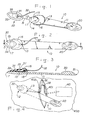
- FIGS. 1-3 show the instrument 10 of the present invention which is an elongated member 11 having hollowed end 12 which receives injection reservoir 30 in a mating, releasable fashion when the fluid conduit of injection reservoir 30 shown as hollow tubing 32 is passed through bore 13.
- the surgeon may grasp tubing 32 after it is passed through bore 13 to retain injection reservoir 30 within hollowed end 12.
- End 12 is configured relative to the injection reservoir to be inserted to achieve a mating relationship and thus, end 12 contains recess 14 to receive the corresponding rear portion of injection reservoir 30 and has a flat surface 15 on which the flat bottom surface 33 of injection reservoir 30 rests.
- FIG. 2 shows, in outline form, the manner in which injection reservoir 30 fits within recess 14.
- FIG 3 better illustrates the manner in which cover 16 which forms recess 14 is configured to blend in with the design of upper surface 34 of injection reservoir 30 which contains region 35 which is the resealable portion of surface 34 that is intended to be pierced by a hypodermic needle.
- End 12 is of an overall elongated shape which is substantially tapered to an edge 17 which extends around at least the front portion of end 12 which edge is shaped to permit end 12 to push aside and possibly sever tissue ahead of end 12 when it is inserted subcutaneously to thereby create a pocket for the injection reservoir 30 being inserted. It is not desirable to have edge 17 highly beveled to a sharp edge since this may result in excessive bleeding and could even result in damage to subcutaneous bodily structures or organs.
- Instrument 10 as shown further contains an optional elongated portion 20 which is opposite end 12 and serves the two-fold purpose of acting as a handle by which the surgeon can guide end 12 with its injection reservoir 30 into the desired subcutaneous site and can be used as a dilator to create a subcutaneous pocket for the injection reservoir before it is actually inserted beneath the patient's tissue using end 12.
- elongated portion 20 has substantially the same general configuration as end 12 when the injection reservoir 30 is placed in recess 14 although portion 20 may be more flattened in configuration to ease insertion of portion 20.
- Portion 20 has a generally tapered edger 21 similar to edge 17 of end 12 to assist in pushing aside tissue as a pocket for the injection reservoir 30 is made.
- the channel present in instrument 10 shown as bore 13 is also optional since cover 16 can be configured to have a space where the tubing passes over end 12 or else cover 16 can simply grasp the portion of injection reservoir 30 lying below the region where the tubing exits from injection reservoir 30.
- the presence of bore 13 does permit the surgeon to use the tubing to hold the injection reservoir in place on end 13 until he desires to release it when the desired subcutaneous site is reached and can serve as a guide for removal of the reservoir.
- the term "channel" as used herein includes a bore as shown or a depression in which the fluid conduit or tubing of the injection reservoir is designed to rest.
- Instrument 10 is shown as having a flat lower surface 18 (rounded beneath end 12) although it could also be slightly rounded and have a beveled edge along its entire length. Similarly, member 11 could be curved to assist the surgeon in passing instrument 10 through an incision. Instrument 10 could be made of any biocompatible metal such as stainless steel or plastic such as polysulfone of the type commonly employed for surgical instruments as long as the material employed will hold its shape for the purposes described herein. A somewhat flexible material may be desirable to permit ease of insertion. The exact nature of the material used to produce instrument 10 forms no part of the present invention.
- FIG. 3 shows more of the detail of the injection reservoir 30 which is a hollow dome of a medical grade material such as a silicone elastomer and contains a hollow interior region 36 which is reached by passing a hypodermic needle (not shown) through resealable region 36 up to metal needlestop 37.
- Tubing 32 is sealingly connected to injection reservoir 30 by means of a removable connector or is cemented in place to provide the center of tubing 32 with access to region 36.
- Tubing 32 then extends to, for example, an inflatable tissue expander prosthesis 40 as shown in FIG. 4 and is attached to that prosthesis in a sealing fashion. If bore 13 is employed, then it is desirable that tubing 32 be capable of being passed through bore 13, so it must be disconnectable at some point along its length.
- Injection reservoir 30 is merely illustrative of one type of such a reservoir that may be used.
- Others such as those taught in U.S. Patent Nos. 3,971,376 to Wichterle; 4,190,040 to Schulte, and 4,543,088 to Bootman, et al. and rectangular, oblong injection reservoirs sold by, for example, McGhan Medical Corporation of Santa Barbara, CA with its Style 20 Round/Style 22 Rectangle McGhan Tissue Expanders (Data Sheet No. M005 1/85) can also be employed.
- the operative site 400 is selected by the surgeon and an incision is made in accordance with well-known surgical techniques.
- a subcutaneous pocket is made and the prosthesis, in this case tissue expander 40, is inserted into that pocket beneath side 401 of the incision in the patient's skin in the usual manner of inserting such prostheses.
- Portion 20 of instrument 10 can be used to create a subcutaneous tunnel for injection reservoir 30 by inserting portion 20 beneath side 402 of the incision in the patient's skin using end 12 as a handle or else a Heger dilator or other surgical dilator can be used to form such a tunnel.
- Injection reservoir 30 is placed on end 12 and tubing 32 is passed through bore 13 by disconnecting it from the remainder of the tubing by means of in-line connector 38 and thereafter reconnecting it to the open end of the tubing.
- the surgeon then passes end 12 of instrument 10 holding the tubing against member 11 to prevent injection reservoir 30 from slipping out of recess 14 and, using portion 20 as a handle, inserts injection reservoir 30 subcutaneously until the desired site for the injection reservoir 30 is reached.
- the surgeon releases his grasp on tubing 32 and holds injection reservoir 30 in place by pressing on the tissue overlying injection reservoir 30 while instrument 10 is withdrawn to leave the injection reservoir 30 in its desired location.
- end 12 of instrument 10 it is also possible to use end 12 of instrument 10 to create a tunnel with the injection reservoir mounted in place so that the tunnel can be formed and the injection reservoir 30 placed subcutaneously in one operation by moving end 12 from side-to-side as end 12 is advanced. After injection reservoir 30 is in place, tubing 32 is removed from bore 13, the remaining tubing 32 is placed subcutaneously and the incision is closed in the usual manner.
- tubing 32 is passed through bore 13 and is used as a guide for end 12 until injection reservoir 30 is reached.
- Edge 17 is used to push aside or cut through any capsule that may have formed until injection reservoir 30 is received within end 12. The surgeon grips the tubing and removes end 12 along with injection reservoir 30. Bore 13 need not be used since end 12 can simply be inserted using tubing 32 as a guide until injection reservoir 30 is reached.
Landscapes
- Health & Medical Sciences (AREA)
- Life Sciences & Earth Sciences (AREA)
- Heart & Thoracic Surgery (AREA)
- Public Health (AREA)
- Veterinary Medicine (AREA)
- Biomedical Technology (AREA)
- Engineering & Computer Science (AREA)
- Animal Behavior & Ethology (AREA)
- General Health & Medical Sciences (AREA)
- Surgery (AREA)
- Oral & Maxillofacial Surgery (AREA)
- Cardiology (AREA)
- Anesthesiology (AREA)
- Pulmonology (AREA)
- Transplantation (AREA)
- Vascular Medicine (AREA)
- Nuclear Medicine, Radiotherapy & Molecular Imaging (AREA)
- Pathology (AREA)
- Hematology (AREA)
- Medical Informatics (AREA)
- Molecular Biology (AREA)
- Infusion, Injection, And Reservoir Apparatuses (AREA)
- Media Introduction/Drainage Providing Device (AREA)
Claims (3)
- Vorrichtung zum subkutanen Anordnen, wobei diese ein selbstschließendes Injektionsreservoir einschließen kann, wobei das Reservoir einen hohlen Innenraum und eine Leitung aufweist zum Herstellen einer Verbindung zwischen dem hohlen Innenraum und dem Innenraum einer implantierbaren, aufweitbaren Prothese, und wobei die Vorrichtung enthält ein langgestrecktes Teil (11) mit einem ersten hohlen Ende (12) mit konischer Konfiguration, mit einem Abdeckteil (16), so daß ein abgesetztes Gehäuse (14) zur Aufnahme des Reservoirs ausgebildet ist und mit einem kegelförmigen Kantenteil (17), um zu ermöglichen, daß das erste Ende (12) davor angeordnetes Gewebe beiseite zu drücken vermag, wenn die Vorrichtung unter die Haut eines menschlichen Körpers eingebracht wird, um das Injektionsreservoir an die gewünschte Stelle unter der Haut zu bringen, und mit einem vom ersten Ende (12) entfernten zweiten Ende (20), das zu einem Griff für die Vorrichtung ausgebildet ist, und in einem kugelförmigen Endteil (21) endet.
- Vorrichtung nach Anspruch 1,
dadurch gekennzeichnet,
daß das erste Ende (12) einen Kanal (13) zur Aufnahme der Leitung für fluides Medium des selbstschließenden Injektionsreservoirs aufweist, wobei der Kanal (13) am ersten Ende (12) dem Griff (20) zugewandt angeordnet ist. - Kombination einer Vorrichtung zum subkutanen Anordnen nach Anspruch 1 oder 2 und einem selbstschließenden Injektionsreservoir mit einem hohlen Innenraum und einer Leitung zum Herstellen einer Verbindung zwischen dem hohlen Innenraum und dem Innenraum einer implantierbaren, aufweitbaren Prothese,
dadurch gekennzeichnet,
daß das abgesetzte Gehäuse (14) mindestens einen Teil des Reservoirs (30) in einer passenden lösbaren Weise abdeckt, und daß die Oberfläche des ersten Endes (12) mit der passenden Oberfläche des Reservoirs (30) zusammenläuft.
Applications Claiming Priority (2)
| Application Number | Priority Date | Filing Date | Title |
|---|---|---|---|
| US06/907,204 US4751926A (en) | 1986-09-12 | 1986-09-12 | Instrument for subcutaneous insertion of an injection reservoir |
| US907204 | 2001-07-17 |
Publications (3)
| Publication Number | Publication Date |
|---|---|
| EP0260080A2 EP0260080A2 (de) | 1988-03-16 |
| EP0260080A3 EP0260080A3 (en) | 1989-02-22 |
| EP0260080B1 true EP0260080B1 (de) | 1992-04-15 |
Family
ID=25423688
Family Applications (1)
| Application Number | Title | Priority Date | Filing Date |
|---|---|---|---|
| EP87307848A Expired - Lifetime EP0260080B1 (de) | 1986-09-12 | 1987-09-04 | Instrument für das Einsetzen eines Injektionsreservoirs |
Country Status (5)
| Country | Link |
|---|---|
| US (1) | US4751926A (de) |
| EP (1) | EP0260080B1 (de) |
| JP (1) | JPS6371261A (de) |
| CA (1) | CA1294844C (de) |
| DE (1) | DE3778257D1 (de) |
Families Citing this family (38)
| Publication number | Priority date | Publication date | Assignee | Title |
|---|---|---|---|---|
| DE3837779A1 (de) * | 1987-11-12 | 1989-05-24 | Ernst Peter Prof Dr M Strecker | Kathetersystem mit infusionskammer |
| FR2649324B1 (fr) * | 1989-07-06 | 1991-10-31 | Dow Corning Sa | Article souple pour traitement chirurgical, ensemble le comprenant et son procede d'utilisation |
| US5165425A (en) * | 1989-07-06 | 1992-11-24 | Dow Corning France S.A. | Method of forming a flap of tissue |
| DE59100448D1 (de) * | 1990-04-20 | 1993-11-11 | Sulzer Ag | Implantat, insbesondere Zwischenwirbelprothese. |
| US5207644A (en) * | 1991-03-04 | 1993-05-04 | Strecker Ernst P | Device with implantable infusion chamber and a catheter extending therefrom |
| US5725493A (en) * | 1994-12-12 | 1998-03-10 | Avery; Robert Logan | Intravitreal medicine delivery |
| ES2225886T3 (es) * | 1995-05-14 | 2005-03-16 | Optonol Ltd. | Implante intraocular, dispositivo de transferencia y metodo de implantacion. |
| IL113723A (en) * | 1995-05-14 | 2002-11-10 | Optonol Ltd | Intraocular implant |
| US5968058A (en) * | 1996-03-27 | 1999-10-19 | Optonol Ltd. | Device for and method of implanting an intraocular implant |
| US5725497A (en) * | 1995-06-07 | 1998-03-10 | American Cyanamid Company | Injection dart system |
| US5868699A (en) * | 1995-06-07 | 1999-02-09 | American Cyanamid Company | Injection dart system |
| US5919160A (en) * | 1996-10-10 | 1999-07-06 | Sanfilippo, Ii; Dominic Joseph | Vascular access device and method of installing same |
| US6203513B1 (en) | 1997-11-20 | 2001-03-20 | Optonol Ltd. | Flow regulating implant, method of manufacture, and delivery device |
| US8313454B2 (en) * | 1997-11-20 | 2012-11-20 | Optonol Ltd. | Fluid drainage device, delivery device, and associated methods of use and manufacture |
| US6558342B1 (en) | 1999-06-02 | 2003-05-06 | Optonol Ltd. | Flow control device, introducer and method of implanting |
| US6468252B1 (en) | 2000-08-03 | 2002-10-22 | Sanfilippo, Ii Dominic J. | Clamp for vascular access device |
| US7862531B2 (en) * | 2004-06-25 | 2011-01-04 | Optonol Ltd. | Flow regulating implants |
| US8246569B1 (en) | 2004-08-17 | 2012-08-21 | California Institute Of Technology | Implantable intraocular pressure drain |
| US20060258994A1 (en) * | 2005-05-12 | 2006-11-16 | Avery Robert L | Implantable delivery device for administering pharmacological agents to an internal portion of a body |
| CA2833354C (en) * | 2006-03-14 | 2015-12-15 | University Of Southern California | Mems device and method for delivery of therapeutic agents |
| US7731700B1 (en) | 2007-06-29 | 2010-06-08 | Walter Samuel Schytte | Subdermal injection port |
| JP5542691B2 (ja) | 2007-12-20 | 2014-07-09 | ユニバーシティ オブ サザン カリフォルニア | 治療薬を送達するための装置および方法 |
| WO2009089094A2 (en) | 2008-01-03 | 2009-07-16 | University Of Southern California | Implantable drug-delivery devices, and apparatus and methods for refilling the devices |
| US8109896B2 (en) * | 2008-02-11 | 2012-02-07 | Optonol Ltd. | Devices and methods for opening fluid passageways |
| AT10474U1 (de) * | 2008-04-15 | 2009-04-15 | A M I Agency For Medical Innov | Portkatheter zum einbringen einer flüssigkeit in ein hohlorgan eines menschlichen oder tierischen körpers |
| WO2009137777A2 (en) | 2008-05-08 | 2009-11-12 | Replenish Pumps, Llc | Implantable drug-delivery devices, and apparatus and methods for filling the devices |
| US9333297B2 (en) | 2008-05-08 | 2016-05-10 | Minipumps, Llc | Drug-delivery pump with intelligent control |
| DK2320989T3 (da) * | 2008-05-08 | 2015-06-22 | Minipumps Llc | Implanterbare pumper og kanyler dertil |
| US8231609B2 (en) | 2008-05-08 | 2012-07-31 | Minipumps, Llc | Drug-delivery pumps and methods of manufacture |
| USD629503S1 (en) | 2009-05-08 | 2010-12-21 | Sean Caffey | Implantable drug-delivery pump |
| US20110034886A1 (en) * | 2009-08-06 | 2011-02-10 | Angiodynamics, Inc. | Implantable medical device tool and method of use |
| WO2011022484A1 (en) | 2009-08-18 | 2011-02-24 | Replenish Pumps. Llc | Electrolytic drug-delivery pump with adaptive control |
| US9603997B2 (en) | 2011-03-14 | 2017-03-28 | Minipumps, Llc | Implantable drug pumps and refill devices therefor |
| US9919099B2 (en) | 2011-03-14 | 2018-03-20 | Minipumps, Llc | Implantable drug pumps and refill devices therefor |
| US10286146B2 (en) | 2011-03-14 | 2019-05-14 | Minipumps, Llc | Implantable drug pumps and refill devices therefor |
| US20160166277A1 (en) * | 2014-12-15 | 2016-06-16 | Biotronik Se & Co. Kg | Implantation Kit and Method for Implantation of an Implantable Medical Device |
| EP3263056A1 (de) * | 2016-06-29 | 2018-01-03 | BIOTRONIK SE & Co. KG | Vorrichtung zur implantation von medizinischen vorrichtungen |
| JP2021531920A (ja) * | 2018-08-02 | 2021-11-25 | バード・ペリフェラル・バスキュラー・インコーポレーテッド | 低傷性の外装を有する植え込み可能なポート配置システム |
Family Cites Families (6)
| Publication number | Priority date | Publication date | Assignee | Title |
|---|---|---|---|---|
| US829409A (en) * | 1905-08-10 | 1906-08-28 | John William Manning | Artery and vein expander. |
| US3416713A (en) * | 1965-05-28 | 1968-12-17 | Stephens Ind Inc | Filament inserting tool |
| US4214585A (en) * | 1978-05-15 | 1980-07-29 | Bailey Paul F Jr | Tool for surgical implantation of an intraocular lens |
| US4190040A (en) * | 1978-07-03 | 1980-02-26 | American Hospital Supply Corporation | Resealable puncture housing for surgical implantation |
| US4615704A (en) * | 1984-11-26 | 1986-10-07 | Dow Corning Corporation | Shape retention tissue expander and method of using |
| US4641648A (en) * | 1985-09-27 | 1987-02-10 | Marshall Shapiro | Surgical instrument |
-
1986
- 1986-09-12 US US06/907,204 patent/US4751926A/en not_active Expired - Fee Related
-
1987
- 1987-06-30 CA CA000540926A patent/CA1294844C/en not_active Expired - Lifetime
- 1987-07-21 JP JP62180221A patent/JPS6371261A/ja active Pending
- 1987-09-04 DE DE8787307848T patent/DE3778257D1/de not_active Expired - Lifetime
- 1987-09-04 EP EP87307848A patent/EP0260080B1/de not_active Expired - Lifetime
Also Published As
| Publication number | Publication date |
|---|---|
| CA1294844C (en) | 1992-01-28 |
| DE3778257D1 (de) | 1992-05-21 |
| EP0260080A3 (en) | 1989-02-22 |
| EP0260080A2 (de) | 1988-03-16 |
| US4751926A (en) | 1988-06-21 |
| JPS6371261A (ja) | 1988-03-31 |
Similar Documents
| Publication | Publication Date | Title |
|---|---|---|
| EP0260080B1 (de) | Instrument für das Einsetzen eines Injektionsreservoirs | |
| US7066878B2 (en) | Penile prosthesis and surgical instruments for implantation of penile prostheses | |
| CN112601575B (zh) | 包括低瘢痕形成外部的可植入端口放置系统 | |
| CA2716525C (en) | Venous access port assembly with push surfaces | |
| US4641648A (en) | Surgical instrument | |
| US4643733A (en) | Permanent reconstruction implant and method of performing human tissue expansion | |
| EP3420988B1 (de) | Werkzeug zur subkutanen verabreichung | |
| US20110034886A1 (en) | Implantable medical device tool and method of use | |
| BR9714740A (pt) | Sistemas, métodos e instrumentos para cirurgia por penetração minimizada | |
| WO2001008563A3 (en) | A surgical access device | |
| AU8391982A (en) | A device for introducing a catheter-cannula into a blood vessel | |
| CA2295831A1 (en) | Method and apparatus for percutaneously accessing an implanted port | |
| EP1482852B1 (de) | Einführungsinstrument für ein penisprothesenimplantat | |
| EP0411767A1 (de) | Aufblasbares chirurgisches Artikel sowie Mittel zu dessen Einbringen in den Körper | |
| JPH10192297A (ja) | 骨手術用腔確保器具 | |
| CN102481191B (zh) | 阴茎假体帽、组件以及植入工具 | |
| KR20170046527A (ko) | 도침 | |
| EP0260081B1 (de) | Injektionsbehälter mit rhombisch geformtem Profil | |
| JPH0975354A (ja) | 剥離子および内視鏡用処置装置 | |
| GB2151927A (en) | Inflatable implant for use in the body | |
| US10806881B2 (en) | Cricotherotomy apparatus and method | |
| JP2007050269A (ja) | 骨手術用腔確保器具 | |
| US11364050B2 (en) | Catheter placing instrument | |
| US5165425A (en) | Method of forming a flap of tissue | |
| US20090082754A1 (en) | Cannula implantation instrument |
Legal Events
| Date | Code | Title | Description |
|---|---|---|---|
| PUAI | Public reference made under article 153(3) epc to a published international application that has entered the european phase |
Free format text: ORIGINAL CODE: 0009012 |
|
| AK | Designated contracting states |
Kind code of ref document: A2 Designated state(s): DE FR GB |
|
| PUAL | Search report despatched |
Free format text: ORIGINAL CODE: 0009013 |
|
| AK | Designated contracting states |
Kind code of ref document: A3 Designated state(s): DE FR GB |
|
| 17P | Request for examination filed |
Effective date: 19890330 |
|
| 17Q | First examination report despatched |
Effective date: 19901022 |
|
| GRAA | (expected) grant |
Free format text: ORIGINAL CODE: 0009210 |
|
| AK | Designated contracting states |
Kind code of ref document: B1 Designated state(s): DE FR GB |
|
| REF | Corresponds to: |
Ref document number: 3778257 Country of ref document: DE Date of ref document: 19920521 |
|
| ET | Fr: translation filed | ||
| PLBE | No opposition filed within time limit |
Free format text: ORIGINAL CODE: 0009261 |
|
| STAA | Information on the status of an ep patent application or granted ep patent |
Free format text: STATUS: NO OPPOSITION FILED WITHIN TIME LIMIT |
|
| 26N | No opposition filed | ||
| PGFP | Annual fee paid to national office [announced via postgrant information from national office to epo] |
Ref country code: FR Payment date: 19930602 Year of fee payment: 7 |
|
| PGFP | Annual fee paid to national office [announced via postgrant information from national office to epo] |
Ref country code: DE Payment date: 19930608 Year of fee payment: 7 |
|
| PGFP | Annual fee paid to national office [announced via postgrant information from national office to epo] |
Ref country code: GB Payment date: 19930614 Year of fee payment: 7 |
|
| PG25 | Lapsed in a contracting state [announced via postgrant information from national office to epo] |
Ref country code: GB Effective date: 19940904 |
|
| GBPC | Gb: european patent ceased through non-payment of renewal fee |
Effective date: 19940904 |
|
| PG25 | Lapsed in a contracting state [announced via postgrant information from national office to epo] |
Ref country code: FR Effective date: 19950531 |
|
| PG25 | Lapsed in a contracting state [announced via postgrant information from national office to epo] |
Ref country code: DE Effective date: 19950601 |
|
| REG | Reference to a national code |
Ref country code: FR Ref legal event code: ST |