EP0260016B1 - Tension bands and methods for their manufacture - Google Patents
Tension bands and methods for their manufacture Download PDFInfo
- Publication number
- EP0260016B1 EP0260016B1 EP87307514A EP87307514A EP0260016B1 EP 0260016 B1 EP0260016 B1 EP 0260016B1 EP 87307514 A EP87307514 A EP 87307514A EP 87307514 A EP87307514 A EP 87307514A EP 0260016 B1 EP0260016 B1 EP 0260016B1
- Authority
- EP
- European Patent Office
- Prior art keywords
- rovings
- layer
- tension
- layers
- tension bands
- Prior art date
- Legal status (The legal status is an assumption and is not a legal conclusion. Google has not performed a legal analysis and makes no representation as to the accuracy of the status listed.)
- Expired - Lifetime
Links
- 238000000034 method Methods 0.000 title claims abstract description 14
- 238000004519 manufacturing process Methods 0.000 title claims abstract description 12
- 229920005989 resin Polymers 0.000 claims abstract description 12
- 239000011347 resin Substances 0.000 claims abstract description 12
- 239000000835 fiber Substances 0.000 claims abstract description 10
- 239000002131 composite material Substances 0.000 claims description 15
- 239000003822 epoxy resin Substances 0.000 claims description 4
- 229920000647 polyepoxide Polymers 0.000 claims description 4
- 239000001307 helium Substances 0.000 description 11
- 229910052734 helium Inorganic materials 0.000 description 11
- SWQJXJOGLNCZEY-UHFFFAOYSA-N helium atom Chemical compound [He] SWQJXJOGLNCZEY-UHFFFAOYSA-N 0.000 description 10
- 239000003365 glass fiber Substances 0.000 description 9
- 239000007788 liquid Substances 0.000 description 7
- IJGRMHOSHXDMSA-UHFFFAOYSA-N Atomic nitrogen Chemical compound N#N IJGRMHOSHXDMSA-UHFFFAOYSA-N 0.000 description 6
- 238000003384 imaging method Methods 0.000 description 6
- 239000000463 material Substances 0.000 description 5
- 239000011521 glass Substances 0.000 description 3
- 229910052757 nitrogen Inorganic materials 0.000 description 3
- 230000005855 radiation Effects 0.000 description 3
- 238000012546 transfer Methods 0.000 description 3
- XEEYBQQBJWHFJM-UHFFFAOYSA-N Iron Chemical compound [Fe] XEEYBQQBJWHFJM-UHFFFAOYSA-N 0.000 description 2
- 230000001133 acceleration Effects 0.000 description 2
- 238000009835 boiling Methods 0.000 description 2
- 238000013461 design Methods 0.000 description 2
- 238000004804 winding Methods 0.000 description 2
- OKTJSMMVPCPJKN-UHFFFAOYSA-N Carbon Chemical compound [C] OKTJSMMVPCPJKN-UHFFFAOYSA-N 0.000 description 1
- 239000004593 Epoxy Substances 0.000 description 1
- 229920000271 Kevlar® Polymers 0.000 description 1
- 229910001069 Ti alloy Inorganic materials 0.000 description 1
- 238000013459 approach Methods 0.000 description 1
- 229910052799 carbon Inorganic materials 0.000 description 1
- 238000010276 construction Methods 0.000 description 1
- 230000001419 dependent effect Effects 0.000 description 1
- 239000007789 gas Substances 0.000 description 1
- 230000005484 gravity Effects 0.000 description 1
- 150000002371 helium Chemical class 0.000 description 1
- 230000003993 interaction Effects 0.000 description 1
- 229910052742 iron Inorganic materials 0.000 description 1
- 238000002955 isolation Methods 0.000 description 1
- 239000004761 kevlar Substances 0.000 description 1
- 238000002595 magnetic resonance imaging Methods 0.000 description 1
- 229910052751 metal Inorganic materials 0.000 description 1
- 239000002184 metal Substances 0.000 description 1
- 230000002787 reinforcement Effects 0.000 description 1
- 230000035939 shock Effects 0.000 description 1
- 239000000725 suspension Substances 0.000 description 1
- 230000002459 sustained effect Effects 0.000 description 1
- 238000012360 testing method Methods 0.000 description 1
- 239000004753 textile Substances 0.000 description 1
Images



Classifications
-
- B—PERFORMING OPERATIONS; TRANSPORTING
- B29—WORKING OF PLASTICS; WORKING OF SUBSTANCES IN A PLASTIC STATE IN GENERAL
- B29C—SHAPING OR JOINING OF PLASTICS; SHAPING OF MATERIAL IN A PLASTIC STATE, NOT OTHERWISE PROVIDED FOR; AFTER-TREATMENT OF THE SHAPED PRODUCTS, e.g. REPAIRING
- B29C69/00—Combinations of shaping techniques not provided for in a single one of main groups B29C39/00 - B29C67/00, e.g. associations of moulding and joining techniques; Apparatus therefore
- B29C69/001—Combinations of shaping techniques not provided for in a single one of main groups B29C39/00 - B29C67/00, e.g. associations of moulding and joining techniques; Apparatus therefore a shaping technique combined with cutting, e.g. in parts or slices combined with rearranging and joining the cut parts
- B29C69/002—Winding
-
- B—PERFORMING OPERATIONS; TRANSPORTING
- B29—WORKING OF PLASTICS; WORKING OF SUBSTANCES IN A PLASTIC STATE IN GENERAL
- B29C—SHAPING OR JOINING OF PLASTICS; SHAPING OF MATERIAL IN A PLASTIC STATE, NOT OTHERWISE PROVIDED FOR; AFTER-TREATMENT OF THE SHAPED PRODUCTS, e.g. REPAIRING
- B29C53/00—Shaping by bending, folding, twisting, straightening or flattening; Apparatus therefor
- B29C53/56—Winding and joining, e.g. winding spirally
- B29C53/564—Winding and joining, e.g. winding spirally for making non-tubular articles
-
- B—PERFORMING OPERATIONS; TRANSPORTING
- B29—WORKING OF PLASTICS; WORKING OF SUBSTANCES IN A PLASTIC STATE IN GENERAL
- B29D—PRODUCING PARTICULAR ARTICLES FROM PLASTICS OR FROM SUBSTANCES IN A PLASTIC STATE
- B29D29/00—Producing belts or bands
-
- B—PERFORMING OPERATIONS; TRANSPORTING
- B29—WORKING OF PLASTICS; WORKING OF SUBSTANCES IN A PLASTIC STATE IN GENERAL
- B29L—INDEXING SCHEME ASSOCIATED WITH SUBCLASS B29C, RELATING TO PARTICULAR ARTICLES
- B29L2029/00—Belts or bands
-
- Y—GENERAL TAGGING OF NEW TECHNOLOGICAL DEVELOPMENTS; GENERAL TAGGING OF CROSS-SECTIONAL TECHNOLOGIES SPANNING OVER SEVERAL SECTIONS OF THE IPC; TECHNICAL SUBJECTS COVERED BY FORMER USPC CROSS-REFERENCE ART COLLECTIONS [XRACs] AND DIGESTS
- Y10—TECHNICAL SUBJECTS COVERED BY FORMER USPC
- Y10S—TECHNICAL SUBJECTS COVERED BY FORMER USPC CROSS-REFERENCE ART COLLECTIONS [XRACs] AND DIGESTS
- Y10S428/00—Stock material or miscellaneous articles
- Y10S428/902—High modulus filament or fiber
-
- Y—GENERAL TAGGING OF NEW TECHNOLOGICAL DEVELOPMENTS; GENERAL TAGGING OF CROSS-SECTIONAL TECHNOLOGIES SPANNING OVER SEVERAL SECTIONS OF THE IPC; TECHNICAL SUBJECTS COVERED BY FORMER USPC CROSS-REFERENCE ART COLLECTIONS [XRACs] AND DIGESTS
- Y10—TECHNICAL SUBJECTS COVERED BY FORMER USPC
- Y10T—TECHNICAL SUBJECTS COVERED BY FORMER US CLASSIFICATION
- Y10T428/00—Stock material or miscellaneous articles
- Y10T428/24—Structurally defined web or sheet [e.g., overall dimension, etc.]
- Y10T428/24132—Structurally defined web or sheet [e.g., overall dimension, etc.] including grain, strips, or filamentary elements in different layers or components parallel
-
- Y—GENERAL TAGGING OF NEW TECHNOLOGICAL DEVELOPMENTS; GENERAL TAGGING OF CROSS-SECTIONAL TECHNOLOGIES SPANNING OVER SEVERAL SECTIONS OF THE IPC; TECHNICAL SUBJECTS COVERED BY FORMER USPC CROSS-REFERENCE ART COLLECTIONS [XRACs] AND DIGESTS
- Y10—TECHNICAL SUBJECTS COVERED BY FORMER USPC
- Y10T—TECHNICAL SUBJECTS COVERED BY FORMER US CLASSIFICATION
- Y10T428/00—Stock material or miscellaneous articles
- Y10T428/24—Structurally defined web or sheet [e.g., overall dimension, etc.]
- Y10T428/24752—Laterally noncoextensive components
-
- Y—GENERAL TAGGING OF NEW TECHNOLOGICAL DEVELOPMENTS; GENERAL TAGGING OF CROSS-SECTIONAL TECHNOLOGIES SPANNING OVER SEVERAL SECTIONS OF THE IPC; TECHNICAL SUBJECTS COVERED BY FORMER USPC CROSS-REFERENCE ART COLLECTIONS [XRACs] AND DIGESTS
- Y10—TECHNICAL SUBJECTS COVERED BY FORMER USPC
- Y10T—TECHNICAL SUBJECTS COVERED BY FORMER US CLASSIFICATION
- Y10T428/00—Stock material or miscellaneous articles
- Y10T428/31504—Composite [nonstructural laminate]
- Y10T428/31511—Of epoxy ether
-
- Y—GENERAL TAGGING OF NEW TECHNOLOGICAL DEVELOPMENTS; GENERAL TAGGING OF CROSS-SECTIONAL TECHNOLOGIES SPANNING OVER SEVERAL SECTIONS OF THE IPC; TECHNICAL SUBJECTS COVERED BY FORMER USPC CROSS-REFERENCE ART COLLECTIONS [XRACs] AND DIGESTS
- Y10—TECHNICAL SUBJECTS COVERED BY FORMER USPC
- Y10T—TECHNICAL SUBJECTS COVERED BY FORMER US CLASSIFICATION
- Y10T428/00—Stock material or miscellaneous articles
- Y10T428/31504—Composite [nonstructural laminate]
- Y10T428/31511—Of epoxy ether
- Y10T428/31525—Next to glass or quartz
Definitions
- the invention relates to tension bands and methods and apparatus for manufacturing such tension bands.
- the invention is concerned in particular with tension bands for use as supports in cryogenic applications.
- Superconducting magnets are commonly used in magnetic resonance imaging (MRI) systems and are essentially solenoids which are cooled to operational temperatures in a bath of liquid helium provided in a cryostat. Liquid helium boils at a temperature of 4.2 K and to maintain this helium bath it is necessary to design a cryostat that reduces to a minimum the transfer of heat from the environment.
- Three methods of heat transfer are usually considered: conduction plus convection through gas (air) between the helium vessel and its environment, radiation from the environment onto the helium vessel, and conduction through the physical support structure of the helium vessel.
- cryostats built to contain imaging magnets are built with a series of radiation shields between the surface of the outer vessel and the helium vessel.
- the intermediate shields are cooled by refrigerators that use external power.
- Others use as an intermediate shield a vessel which contains liquid nitrogen which boils at 77 K at normal atmospheric pressure. In this case, the shield is maintained at an intermediate temperature by the boiling nitrogen and energy from the environment is absorbed by the latent heat of boiling.
- the weight of the imaging magnet and vessel range from 1500 to 4000 kilograms dependent upon magnet field strength and vessel configuration.
- tension bands have a good thermal/tensile strength, they have to be produced individually at very high cost if they are to have sufficient strength for use in heavy duty applications such as cryostats for NMR imaging magnets.
- GB-A-835355 discloses a spring assembly made from glass fibres.
- FR-A-2568171 describes the winding of a fibre length onto a mandrel.
- US-A-2980158 describes the construction of an archery bow which could comprise glass fibre.
- Non of these arrangements is relevant to the problems addressed by this invention since in the earlier cases the performance of the products is governed by the stiffness (spring rate) of the products rather than their ultimate tensile strength. Furthermore, there is no consideration on the thermal conductivity properties of the product.
- EP-A-193479 describes a textile material having a number of layers in which the fibres of the layers extend transversly with respect to the length of the reinforcement. Again, this is not relevant to the present problem which is concerned with low thermal conductivity tension bands.
- a method of manufacturing a plurality of tension bands in which a composite, uncured structure is manufactured by laying down on a mandrel one upon the other a number of layers of elongate resin impregnated fibre rovings, each layer comprising a number of rovings extending side by side within the layer, the rovings in each layer being laid down so that they are laterally offset from the rovings in adjacent layers; curing the composite structure; and cutting the cured composite structure into two or more tension bands.
- the rovings in each layer are laid down laterally offset in a regular manner from the rovings in adjacent layers by a predetermined amount and preferably the degree of overlap is substantially 50%.
- This has resulted in a significant increase in tensile strength compared with known tension bands of similar dimensions. This means that it is possible to achieve a high tensile and fatigue strength tension band while minimising the cross-section of the band and thus minimising the conducted heat load within a cryostat or other cryogenic environment in which the band is used.
- this method allows mass production of high strength tension bands at a much lower cost than previously.
- a "roving” is defined as comprising a bundle of individual fibres and will typically have a rectangular cross-section.
- the rovings may be woven or, preferably, non-woven (ie unidirectional).
- the resin is preferably an epoxy resin.
- each layer may be of the same material, it is preferred to include one or more partial layers of rovings of a different material from the remainder of the layers. These additional partial layers may be in form of pre-impregnated fibre sheets of unidirectional fibres.
- tension band is in the form of an elongate, endless loop in which case the inserts are provided at each end of the loop.
- the advantage of this is that any failure in the tension band will occur within the length of the band rather than at one of the ends which results in an increase in fatigue strength.
- the fibres preferably comprise glass fibres such as S-glass fibres although other fibres such as carbon fibres or Kevlar fibres could be used.
- one or more fibre sheets are periodically laid down on the most recently laid layer. These sheets may be made from the same or different fibres from the other layers.
- the laid down, uncured rovings are compacted prior to curing.
- Apparatus for manufacturing an uncured structure which after curing comprises a tension band may comprise a first support to which is rotatably mounted a mandrel; a second support for a resin bondable fibre roving store; indexing means to which rovings from the store are fed, the indexing means and the mandrel being relatively movable whereby in use layers of rovings are laid down on the mandrel, the rovings in each layer being laterally offset from the rovings in adjacent layers; and drive means for causing relative movement between the indexing means and the mandrel.
- the apparatus may further comprise a resin bath through which the rovings pass prior to being laid down on the mandrel.
- the rovings could be pre-impregnated with resin before being positioned in the store or impregnated after laying down on the mandrel.
- the tension band shown in Figures 1 and 2 has an elongate portion 1 with a length of about 350 mm and a pair of semi-circular end portions 2 with inner radii of about 12.5 mm and outer radii of about 15.3 mm.
- the band is built up from a number of first layers of rovings of glass fibre, four of the layers 3-6 being shown in Figure 2.
- the rovings shown in Figure 2 are formed by bundles of S-glass fibres impregnated with an epoxy resin.
- the rovings in each layer 3-6 are laterally offset from the rovings in the adjacent layers.
- the rovings in one layer are offset by about 50% from the rovings in each adjacent layer. This regular offset, which is applied throughout the thickness of the band, leads to a high tensile strength band being produced.
- each interleaved, partial layer is shorter than a radially inner interleaved, partial layer. This leads to a smooth taper without high stress positions and a strong band.
- the purpose of the interleaved layers is to move the region of failure from the end portions 2 to the elongate portion 1.
- the S glass layers extend fully around the tension band.
- FIGs 3 to 5 illustrate an example of apparatus for manufacturing the tension band shown in Figures 1 and 2.
- the apparatus comprises a support structure 7 on which is rotatably mounted a spindle 8 carrying a platen or mandrel 9.
- the support structure 7 also supports a platform 10 on which is mounted at one end a store support 11.
- Rotatably mounted in the store support 11 is a cylinder 12 around which is wound a length of S glass fibre rovings.
- Below the store support 11 is positioned a heater control 13 to control a heater (not shown) in a resin bath 14 through which the rovings pass after being unwound from the store 12.
- the roving passes from the indexing unit 16 to the mandrel 9 onto which it is wound.
- Movement of the indexing unit 16 is controlled by a drive motor 17 via a drive chain 31 and drive gear 15.
- the drive motor 17 also causes rotation of the mandrel 9.
- a tensioning element (not shown) is provided to tension the roving drawn off the store 12.
- the indexing unit 16 comprises a platform 32 on which are mounted a pair of half nuts 33, 34.
- the platform 32 can take up one of two lateral positions under the control of a pneumatic actuator 35 having an actuating element 36 which engages a depending flange 37 mounted underneath the platform 32.
- the half-nut 34 engages the thread of a lead screw 38 rotatably mounted between bearings 39, 40 supported in side walls (not shown) of the apparatus.
- the half-nut 33 engages the thread of a lead screw 41 rotatably mounted between bearings 42, 43 also mounted to the side walls of the apparatus.
- Gears 44, 45 are non-rotatably mounted to the lead screws 41, 38 respectively axially outwardly of the bearings 43, 40 while a further drive gear 46 is non-rotatably mounted to the lead screw 38.
- the drive chain 31 is entrained around the drive gear 46.
- the drive chain 31 is also entrained around a gear 47 non-rotatably mounted to the shaft 8 on which the spindle 9 is mounted.
- the drive motor 17 causes rotation of the lead screws 38, 41 and the spindle 8.
- the half-nuts 33, 34 are relatively off-set in the axial direction of the lead screws 38, 41 by one half pitch of the lead screw threads which are the same. The reason for this will be described in more detail below.
- the roving 30 passes from the resin bath 14 through an aperture 48 in a plate 49 mounted to the platform 32 before extending to the mandrel 9.
- a pair of detectors 50, 51, such as proximity switches are mounted in alignment with the flange 37 and on opposite sides of the platform 32 so that as the platform 32 approaches each end of its traverse, the corresponding proximity switch will be actuated and a control circuit (not shown) will cause the pneumatic actuator to move the platform 32 from its current position to its other position.
- the glass fibre roving 30 is withdrawn from the store 12 by actuating the drive motor 17 and is drawn along the path shown in Figure 3 onto the mandrel 9 as the mandrel is rotated.
- the indexing unit 16 moves parallel with the mandrel 9 due to the engagement of one of the half nuts 33, 34 with the corresponding lead screw 41, 38 so that a layer of rovings, such as the layer 3 in Figure 2, is built up.
- the corresponding proximity switch 50,51 is actuated causing the control circuit, such as a flip-flop, to actuate the pneumatic actuator 35. This will cause the other half-nut 33, 34 to engage its lead screws 38, 41.
- the lead screws 38, 41 rotate in opposite directions due to the gears 44, 45 so that the platform 32 will start to return to its initial position. Since the half-nuts 33, 34 are offset by half a thread pitch the first roving of the next layer will overlap by equal amounts the last two rovings of the preceding layer. Thereafter, the indexing unit 16 moves at the original speed so that the next layer is fully laid down. This is repeated as necessary with the rovings of each layer overlapping the rovings of the preceding layer. At intervals, the drive motor 17 is stopped and fibre sheets of a different material are manually laid onto the mandrel 9 at its ends, corresponding to the curved portions 2 of the tension band. Typically, these sheets will be made from R glass fibres.
- the mandrel 9 is dismounted from the support 7 and positioned between a pair of compacting plates (not shown) which squeeze the laminated rovings to a pre-determined thickness to generate a composite laminate 52 ( Figure 6).
- the compacted, composite laminate is then cured in a conventional manner and finally split in the elongate direction into a number of tension bands 53-56.
- a composite laminate is formed having a width of 200 mm and this is divided into 10 tension bands, each having a width of 20 mm.
- the endmost bands 57,58 are usually discarded since these may have an over supply of resin.
- Figure 7 illustrates an alternative form of tension band 59 which is constructed at one end 60 in a similar manner to the example shown in Figure 1 but at its other end 61 the arms of the band are drawn together and cured inside a metal ferrule 62 which is externally screw threaded.
- the rovings are secured in the ferrule 62 using the method described in EP-A-0207972, the disclosure of which is incorporated herein by reference. This allows the tension band to be connected at the end 61 in a manner similar to a conventional tension rod.
- Figure 8 illustrates an example of the use of a tension band as illustrated at 18.
- Figure 8 illustrates part of a cryostat having a liquid helium vessel 19 including a rod 20 around which the band 18 is mounted.
- the band 18 extends through an aperture 21 in a radiation shield 22 and through an aperture 23 of part of a liquid nitrogen vessel 24.
- the other end of the tension band 18 is mounted about a rod 25 supported in a titanium alloy clevis 26 anchored to a bracket 27 mounted within part of a vacuum chamber 28.
Landscapes
- Engineering & Computer Science (AREA)
- Mechanical Engineering (AREA)
- Moulding By Coating Moulds (AREA)
- Auxiliary Devices For And Details Of Packaging Control (AREA)
- Nonwoven Fabrics (AREA)
- Laminated Bodies (AREA)
- Magnetic Resonance Imaging Apparatus (AREA)
- Forging (AREA)
- Reinforced Plastic Materials (AREA)
- Preliminary Treatment Of Fibers (AREA)
- Saccharide Compounds (AREA)
- Nitrogen Condensed Heterocyclic Rings (AREA)
- Yarns And Mechanical Finishing Of Yarns Or Ropes (AREA)
- Ropes Or Cables (AREA)
Abstract
Description
- The invention relates to tension bands and methods and apparatus for manufacturing such tension bands. The invention is concerned in particular with tension bands for use as supports in cryogenic applications.
- Superconducting magnets are commonly used in magnetic resonance imaging (MRI) systems and are essentially solenoids which are cooled to operational temperatures in a bath of liquid helium provided in a cryostat. Liquid helium boils at a temperature of 4.2 K and to maintain this helium bath it is necessary to design a cryostat that reduces to a minimum the transfer of heat from the environment. Three methods of heat transfer are usually considered: conduction plus convection through gas (air) between the helium vessel and its environment, radiation from the environment onto the helium vessel, and conduction through the physical support structure of the helium vessel.
- To deal with the problems of heat transfer, cryostats built to contain imaging magnets are built with a series of radiation shields between the surface of the outer vessel and the helium vessel. In some configurations of imaging cryostats the intermediate shields are cooled by refrigerators that use external power. Others use as an intermediate shield a vessel which contains liquid nitrogen which boils at 77 K at normal atmospheric pressure. In this case, the shield is maintained at an intermediate temperature by the boiling nitrogen and energy from the environment is absorbed by the latent heat of boiling.
- It is necessary to design a support system for the elements of the cryostat which is strong enough to support the vessels and shields and which does not allow heat to be conducted directly from the outer vessel to the helium can. The forces which the elements of the cryostat undergo include gravity, acceleration during movement of the cryostat, and magnetic interactions with the structural iron.
- Conventionally, a system of struts operating in three dimensions and supporting the vessels while acting in tension has been used for NMR imaging magnet cryostats. Examples of these struts are described in EP-A-0207972. Unique combinations of strength and thermal isolation are required for NMR magnets.
- The weight of the imaging magnet and vessel range from 1500 to 4000 kilograms dependent upon magnet field strength and vessel configuration.
- Until recently, support systems were designed solely to deal with gravitational forces. Relatively recently, it has become an operational requirement that imaging magnets are built into mobile scanners housed in custom built bodies on air ride trucks. The vibration and impact accelerations experienced by the magnet can occur in any of three dimensions.
- These requirements have resulted in the need for a support member capable of withstanding a sustained fatigue loading of 15 to 30 KN, with an ultimate tensile strength of greater than 75 KN. This represents 2 g fatigue and 5 g shock loading, for the heaviest magnet considered, when distributed across 4 suspension members.
- A paper entitled "Fatigue Resistance of a Uniaxial S-Glass/Epoxy Composite at Room and Liquid Helium Temperatures" by Tobler and Read in J. Composite Materials, Vol. 10 (January 1976), p.32 and a paper entitled "Filament Wound Composite Thermal Isolator Structures for Cryogenic Dewars and Instruments" by Morris in Composites for Extreme Environments, ASTM SDP768 N.R.A. Adsit, Ed, American Society for Testing Materials 1982, p. 95-109 describe composite materials for manufacturing tension bands which have been proposed in the past for satisfying the above requirements. These papers describe a variety of uses for such tension bands including their use as thermal isolator straps for cryogenic dewars and instruments.
- Although these tension bands have a good thermal/tensile strength, they have to be produced individually at very high cost if they are to have sufficient strength for use in heavy duty applications such as cryostats for NMR imaging magnets.
- GB-A-835355 discloses a spring assembly made from glass fibres. FR-A-2568171 describes the winding of a fibre length onto a mandrel. US-A-2980158 describes the construction of an archery bow which could comprise glass fibre. Non of these arrangements is relevant to the problems addressed by this invention since in the earlier cases the performance of the products is governed by the stiffness (spring rate) of the products rather than their ultimate tensile strength. Furthermore, there is no consideration on the thermal conductivity properties of the product.
- EP-A-193479 describes a textile material having a number of layers in which the fibres of the layers extend transversly with respect to the length of the reinforcement. Again, this is not relevant to the present problem which is concerned with low thermal conductivity tension bands.
- In accordance with the present invention, we provide a method of manufacturing a plurality of tension bands in which a composite, uncured structure is manufactured by laying down on a mandrel one upon the other a number of layers of elongate resin impregnated fibre rovings, each layer comprising a number of rovings extending side by side within the layer, the rovings in each layer being laid down so that they are laterally offset from the rovings in adjacent layers; curing the composite structure; and cutting the cured composite structure into two or more tension bands.
- In the invention, the rovings in each layer are laid down laterally offset in a regular manner from the rovings in adjacent layers by a predetermined amount and preferably the degree of overlap is substantially 50%. This has resulted in a significant increase in tensile strength compared with known tension bands of similar dimensions. This means that it is possible to achieve a high tensile and fatigue strength tension band while minimising the cross-section of the band and thus minimising the conducted heat load within a cryostat or other cryogenic environment in which the band is used. In addition, this method allows mass production of high strength tension bands at a much lower cost than previously.
- In this context, a "roving" is defined as comprising a bundle of individual fibres and will typically have a rectangular cross-section.
- The rovings may be woven or, preferably, non-woven (ie unidirectional).
- The resin is preferably an epoxy resin.
- Although the rovings in each layer may be of the same material, it is preferred to include one or more partial layers of rovings of a different material from the remainder of the layers. These additional partial layers may be in form of pre-impregnated fibre sheets of unidirectional fibres.
- The use of these additional layers is particularly advantageous when the tension band is in the form of an elongate, endless loop in which case the inserts are provided at each end of the loop. The advantage of this is that any failure in the tension band will occur within the length of the band rather than at one of the ends which results in an increase in fatigue strength.
- The fibres preferably comprise glass fibres such as S-glass fibres although other fibres such as carbon fibres or Kevlar fibres could be used.
- The advantage of these new tension bands over the conventional tension rods which have previously been used can be seen by comparing the cross-sectional area of a tension band with the cross-sectional area of a tension rod providing the same tensile strength. Thus, a tension band having a cross-section of about 60 mm² is equivalent to a tension rod of the type described in WO86/04016 having a cross-section of about 78 mm². This reduction in cross-section leads to a reduction in the heat conduction capability of the band which is very important when the band is used in a cryogenic application and in the cost of the band.
- Preferably, during the laying down step, one or more fibre sheets are periodically laid down on the most recently laid layer. These sheets may be made from the same or different fibres from the other layers.
- Preferably, the laid down, uncured rovings are compacted prior to curing.
- Apparatus for manufacturing an uncured structure which after curing comprises a tension band may comprise a first support to which is rotatably mounted a mandrel; a second support for a resin bondable fibre roving store; indexing means to which rovings from the store are fed, the indexing means and the mandrel being relatively movable whereby in use layers of rovings are laid down on the mandrel, the rovings in each layer being laterally offset from the rovings in adjacent layers; and drive means for causing relative movement between the indexing means and the mandrel.
- The apparatus may further comprise a resin bath through which the rovings pass prior to being laid down on the mandrel. Alternatively, the rovings could be pre-impregnated with resin before being positioned in the store or impregnated after laying down on the mandrel.
- Some examples of tension bands and apparatus for implementing methods of manufacturing tension bands in accordance with the present invention will now be described with reference to the accompanying drawings, in which:-
- Figure 1 is a side view of one example of a tension band;
- Figure 2 is an enlarged, partial section taken on the line A-A in Figure 1;
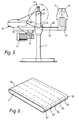
- Figure 3 is a schematic, side view of apparatus for manufacturing the tension band;
- Figure 4 is a schemetic, partial plan of the apparatus shown in Figure 3;
- Figure 5 illustrates schematically the indexing components of the apparatus;
- Figure 6 illustrates a cured composite structure;
- Figure 7 is a side view of a second example of a tension band; and,
- Figure 8 illustrates a tension band supporting a liquid helium vessel of a cryostat.
- The tension band shown in Figures 1 and 2 has an
elongate portion 1 with a length of about 350 mm and a pair ofsemi-circular end portions 2 with inner radii of about 12.5 mm and outer radii of about 15.3 mm. The band is built up from a number of first layers of rovings of glass fibre, four of the layers 3-6 being shown in Figure 2. The rovings shown in Figure 2 are formed by bundles of S-glass fibres impregnated with an epoxy resin. As can be seen in Figure 2, the rovings in each layer 3-6 are laterally offset from the rovings in the adjacent layers. In practice, the rovings in one layer are offset by about 50% from the rovings in each adjacent layer. This regular offset, which is applied throughout the thickness of the band, leads to a high tensile strength band being produced. - It will be seen in Figure 1 that the ends of the
elongate section 1 taper outwardly towards thesemi-circular portions 2. This is due to the interleaving of additional short second layers of unidirectional R glass pre-impregnated rovings in sheets at each end during manufacture of the band. These additional partial layers may be laid between each of the main layers extending throughout the length of the tension band (such as layers 3-6) or between only some of these layers. - Preferably, each interleaved, partial layer is shorter than a radially inner interleaved, partial layer. This leads to a smooth taper without high stress positions and a strong band.
- The purpose of the interleaved layers is to move the region of failure from the
end portions 2 to theelongate portion 1. - An example of a typical laminate is given in the following Table with the innermost layers listed first.

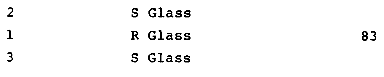
- The S glass layers extend fully around the tension band.
- Figures 3 to 5 illustrate an example of apparatus for manufacturing the tension band shown in Figures 1 and 2. The apparatus comprises a
support structure 7 on which is rotatably mounted aspindle 8 carrying a platen ormandrel 9. Thesupport structure 7 also supports aplatform 10 on which is mounted at one end a store support 11. Rotatably mounted in the store support 11 is acylinder 12 around which is wound a length of S glass fibre rovings. Below the store support 11 is positioned aheater control 13 to control a heater (not shown) in aresin bath 14 through which the rovings pass after being unwound from thestore 12. As therovings 30 pass through theresin bath 14 they are impregnated with epoxy resin. They then pass to anindexing unit 16. The roving passes from theindexing unit 16 to themandrel 9 onto which it is wound. - Movement of the
indexing unit 16 is controlled by adrive motor 17 via adrive chain 31 and drivegear 15. Thedrive motor 17 also causes rotation of themandrel 9. In addition, a tensioning element (not shown) is provided to tension the roving drawn off thestore 12. - The
indexing unit 16 comprises aplatform 32 on which are mounted a pair ofhalf nuts platform 32 can take up one of two lateral positions under the control of apneumatic actuator 35 having anactuating element 36 which engages a dependingflange 37 mounted underneath theplatform 32. In the position shown in Figures 4 and 5, the half-nut 34 engages the thread of alead screw 38 rotatably mounted betweenbearings 39, 40 supported in side walls (not shown) of the apparatus. In the other position of theplatform 32, in which the platform is moved to the right, as seen in Figure 4, the half-nut 33 engages the thread of alead screw 41 rotatably mounted betweenbearings Gears bearings 43, 40 while afurther drive gear 46 is non-rotatably mounted to thelead screw 38. Thedrive chain 31 is entrained around thedrive gear 46. - The
drive chain 31 is also entrained around agear 47 non-rotatably mounted to theshaft 8 on which thespindle 9 is mounted. Thus, thedrive motor 17 causes rotation of the lead screws 38, 41 and thespindle 8. - The half-
nuts - The roving 30 passes from the
resin bath 14 through anaperture 48 in aplate 49 mounted to theplatform 32 before extending to themandrel 9. - A pair of
detectors flange 37 and on opposite sides of theplatform 32 so that as theplatform 32 approaches each end of its traverse, the corresponding proximity switch will be actuated and a control circuit (not shown) will cause the pneumatic actuator to move theplatform 32 from its current position to its other position. - In operation, the glass fibre roving 30 is withdrawn from the
store 12 by actuating thedrive motor 17 and is drawn along the path shown in Figure 3 onto themandrel 9 as the mandrel is rotated. During this rotation, theindexing unit 16 moves parallel with themandrel 9 due to the engagement of one of thehalf nuts corresponding lead screw layer 3 in Figure 2, is built up. Once theindexing unit 16 reaches the end of its path, the correspondingproximity switch pneumatic actuator 35. This will cause the other half-nut gears platform 32 will start to return to its initial position. Since the half-nuts indexing unit 16 moves at the original speed so that the next layer is fully laid down. This is repeated as necessary with the rovings of each layer overlapping the rovings of the preceding layer. At intervals, thedrive motor 17 is stopped and fibre sheets of a different material are manually laid onto themandrel 9 at its ends, corresponding to thecurved portions 2 of the tension band. Typically, these sheets will be made from R glass fibres. - After winding, the
mandrel 9 is dismounted from thesupport 7 and positioned between a pair of compacting plates (not shown) which squeeze the laminated rovings to a pre-determined thickness to generate a composite laminate 52 (Figure 6). The compacted, composite laminate is then cured in a conventional manner and finally split in the elongate direction into a number of tension bands 53-56. Typically, a composite laminate is formed having a width of 200 mm and this is divided into 10 tension bands, each having a width of 20 mm. Theendmost bands - Figure 7 illustrates an alternative form of
tension band 59 which is constructed at oneend 60 in a similar manner to the example shown in Figure 1 but at itsother end 61 the arms of the band are drawn together and cured inside ametal ferrule 62 which is externally screw threaded. The rovings are secured in theferrule 62 using the method described in EP-A-0207972, the disclosure of which is incorporated herein by reference. This allows the tension band to be connected at theend 61 in a manner similar to a conventional tension rod. - Figure 8 illustrates an example of the use of a tension band as illustrated at 18. Figure 8 illustrates part of a cryostat having a
liquid helium vessel 19 including arod 20 around which theband 18 is mounted. Theband 18 extends through anaperture 21 in aradiation shield 22 and through anaperture 23 of part of aliquid nitrogen vessel 24. The other end of thetension band 18 is mounted about arod 25 supported in atitanium alloy clevis 26 anchored to abracket 27 mounted within part of avacuum chamber 28.
Claims (9)
- A method of manufacturing a plurality of tension bands (53-56) in which a composite, uncured structure (52) is manufactured by laying down on a mandrel (9) one upon the other a number of layers (3-6) of elongate resin impregnated fibre rovings, each layer comprising a number of rovings extending side by side within the layer, the rovings in each layer being laid down so that they are laterally offset from the rovings in adjacent layers; curing the composite structure; and cutting the cured composite structure into two or more tension bands.
- A method according to claim 1, wherein the laid down, uncured rovings are compacted prior to curing.
- A method according to claim 1 or claim 2, wherein during the laying down step, one or more fibre sheets are periodically laid down on the most recently laid layer of rovings.
- A method according to claim 3, wherein the cured tension band is in the form of an elongate endless loop, the fibre sheets being laid down around the ends of the loop.
- A method according to any of the preceding claims, wherein each roving overlaps substantially 50% of the rovings in adjacent layers.
- A method according to any of the preceding claims wherein the rovings have a rectangular cross-section.
- A method according to any of the preceding claims, wherein the resin comprises epoxy resin.
- A method according to any of the preceding claims, wherein the rovings are non-woven.
- A cryostat having a number of heat flow restricting components supported by tension bands manufactured according to any of claims 1 to 8.
Priority Applications (1)
| Application Number | Priority Date | Filing Date | Title |
|---|---|---|---|
| AT87307514T ATE86921T1 (en) | 1986-09-08 | 1987-08-25 | STRAPS AND METHOD OF PRODUCTION. |
Applications Claiming Priority (2)
| Application Number | Priority Date | Filing Date | Title |
|---|---|---|---|
| GB868621563A GB8621563D0 (en) | 1986-09-08 | 1986-09-08 | Tension bands |
| GB8621563 | 1986-09-08 |
Publications (3)
| Publication Number | Publication Date |
|---|---|
| EP0260016A2 EP0260016A2 (en) | 1988-03-16 |
| EP0260016A3 EP0260016A3 (en) | 1988-12-28 |
| EP0260016B1 true EP0260016B1 (en) | 1993-03-17 |
Family
ID=10603824
Family Applications (1)
| Application Number | Title | Priority Date | Filing Date |
|---|---|---|---|
| EP87307514A Expired - Lifetime EP0260016B1 (en) | 1986-09-08 | 1987-08-25 | Tension bands and methods for their manufacture |
Country Status (7)
| Country | Link |
|---|---|
| US (1) | US4818582A (en) |
| EP (1) | EP0260016B1 (en) |
| JP (1) | JPS6369623A (en) |
| AT (1) | ATE86921T1 (en) |
| DE (1) | DE3784815T2 (en) |
| ES (1) | ES2039447T3 (en) |
| GB (1) | GB8621563D0 (en) |
Families Citing this family (1)
| Publication number | Priority date | Publication date | Assignee | Title |
|---|---|---|---|---|
| US5164255A (en) * | 1989-08-31 | 1992-11-17 | E. I. Du Pont De Nemours And Company | Nonwoven preform sheets of fiber reinforced resin chips |
Family Cites Families (8)
| Publication number | Priority date | Publication date | Assignee | Title |
|---|---|---|---|---|
| DE1297868B (en) * | 1954-09-09 | 1969-06-19 | Minnesota Mining & Mfg | Manufacture of glass-reinforced plastic sheets |
| US2829881A (en) * | 1957-02-13 | 1958-04-08 | Carrier Conveyor Corp | Vibratory spring of embedded filaments |
| US2980158A (en) * | 1958-04-10 | 1961-04-18 | Parallel Products Company | Method and mold for producing an archery bow |
| US3279278A (en) * | 1964-04-24 | 1966-10-18 | Bendix Corp | Tension-torsion tie-bar and end fittings therefor |
| US3277959A (en) * | 1964-08-12 | 1966-10-11 | Du Pont | Plastic tube heat exchanger and process of making |
| US3668740A (en) * | 1970-11-27 | 1972-06-13 | Owens Corning Fiberglass Corp | High strength strap and method of making it |
| FR2568171B1 (en) * | 1984-07-30 | 1986-08-29 | Garbolino Sa Ets | PROCESS FOR THE PRODUCTION OF A TABLECLOTH CONSISTING OF WIRES FORMED OF RESISTANT FILAMENTS, APPLICATION TO THE PRODUCTION OF TUBULAR ELEMENTS AND TUBULAR ELEMENTS THUS OBTAINED |
| FR2577947B1 (en) * | 1985-02-22 | 1987-03-06 | Chomarat & Cie | TEXTILE REINFORCEMENT FOR USE IN THE PRODUCTION OF LAMINATE COMPLEXES AND METHOD FOR OBTAINING SAME |
-
1986
- 1986-09-08 GB GB868621563A patent/GB8621563D0/en active Pending
-
1987
- 1987-08-20 US US07/087,223 patent/US4818582A/en not_active Expired - Lifetime
- 1987-08-25 DE DE8787307514T patent/DE3784815T2/en not_active Expired - Fee Related
- 1987-08-25 ES ES198787307514T patent/ES2039447T3/en not_active Expired - Lifetime
- 1987-08-25 AT AT87307514T patent/ATE86921T1/en not_active IP Right Cessation
- 1987-08-25 EP EP87307514A patent/EP0260016B1/en not_active Expired - Lifetime
- 1987-09-08 JP JP62225126A patent/JPS6369623A/en active Pending
Also Published As
| Publication number | Publication date |
|---|---|
| DE3784815D1 (en) | 1993-04-22 |
| US4818582A (en) | 1989-04-04 |
| GB8621563D0 (en) | 1986-10-15 |
| DE3784815T2 (en) | 1993-09-16 |
| EP0260016A2 (en) | 1988-03-16 |
| ES2039447T3 (en) | 1993-10-01 |
| EP0260016A3 (en) | 1988-12-28 |
| JPS6369623A (en) | 1988-03-29 |
| ATE86921T1 (en) | 1993-04-15 |
Similar Documents
| Publication | Publication Date | Title |
|---|---|---|
| US5685525A (en) | Carbon fiber reinforced resin coil spring | |
| US4968545A (en) | Composite tube and method of manufacture | |
| US4741873A (en) | Method for forming rigid composite preforms | |
| US20030062647A1 (en) | Method of producing a hybrid matrix fiber composite | |
| GB2503190A (en) | Structurally self-supporting superconducting magnet with support for shield coils | |
| US4947017A (en) | Composite weld gun and method of making same | |
| US6325108B1 (en) | Prestressed composite cryogenic piping | |
| US4963301A (en) | Method for fabrication of refractory composite tubing | |
| US4818582A (en) | Tension bands and methods for their manufacture | |
| US5683059A (en) | Bobbin for superconducting coils | |
| US5753324A (en) | Fiber-reinforced composite cylindrical form | |
| JP3771360B2 (en) | Tubular body made of fiber reinforced composite material | |
| US20150182824A1 (en) | Shaft made of fiber-reinforced composite material | |
| US4807531A (en) | Contemporary composite polar boss | |
| JP7645991B2 (en) | Magnetospinal | |
| Hanson | Effect of Temperature on Tensile and Creep Characteristics of PRD49 Fiber/Epoxy Composites. | |
| JP4877153B2 (en) | Fiber-reinforced composite material molding method | |
| JPH0792396A (en) | CFRP optical tube | |
| WO1986004016A1 (en) | Improvements relating to epoxy bonded glass fibre rods | |
| Wang | Bearing behavior of triaxially braided flat and tubular composites | |
| JPS63278827A (en) | Preparation of tube-like body such as fishing rod, golf shaft and the like | |
| KR880000415Y1 (en) | fishing rod | |
| JPH057023A (en) | Integrally molded heat insulating retainer | |
| Elawadly et al. | Compression response of fiber reinforced composite tubes | |
| JP3601608B2 (en) | Cryogenic fiber reinforced plastic material |
Legal Events
| Date | Code | Title | Description |
|---|---|---|---|
| PUAI | Public reference made under article 153(3) epc to a published international application that has entered the european phase |
Free format text: ORIGINAL CODE: 0009012 |
|
| AK | Designated contracting states |
Kind code of ref document: A2 Designated state(s): AT BE CH DE ES FR GB IT LI LU NL SE |
|
| PUAL | Search report despatched |
Free format text: ORIGINAL CODE: 0009013 |
|
| AK | Designated contracting states |
Kind code of ref document: A3 Designated state(s): AT BE CH DE ES FR GB IT LI LU NL SE |
|
| 17P | Request for examination filed |
Effective date: 19890608 |
|
| RAP1 | Party data changed (applicant data changed or rights of an application transferred) |
Owner name: OXFORD ADVANCED TECHNOLOGY LIMITED |
|
| 17Q | First examination report despatched |
Effective date: 19891201 |
|
| RAP1 | Party data changed (applicant data changed or rights of an application transferred) |
Owner name: OXFORD MEDICAL LIMITED |
|
| GRAA | (expected) grant |
Free format text: ORIGINAL CODE: 0009210 |
|
| AK | Designated contracting states |
Kind code of ref document: B1 Designated state(s): AT BE CH DE ES FR GB IT LI LU NL SE |
|
| REF | Corresponds to: |
Ref document number: 86921 Country of ref document: AT Date of ref document: 19930415 Kind code of ref document: T |
|
| REF | Corresponds to: |
Ref document number: 3784815 Country of ref document: DE Date of ref document: 19930422 |
|
| ITF | It: translation for a ep patent filed | ||
| ET | Fr: translation filed | ||
| PGFP | Annual fee paid to national office [announced via postgrant information from national office to epo] |
Ref country code: AT Payment date: 19930805 Year of fee payment: 7 |
|
| PGFP | Annual fee paid to national office [announced via postgrant information from national office to epo] |
Ref country code: SE Payment date: 19930806 Year of fee payment: 7 |
|
| PGFP | Annual fee paid to national office [announced via postgrant information from national office to epo] |
Ref country code: CH Payment date: 19930825 Year of fee payment: 7 |
|
| PGFP | Annual fee paid to national office [announced via postgrant information from national office to epo] |
Ref country code: BE Payment date: 19930909 Year of fee payment: 7 |
|
| PGFP | Annual fee paid to national office [announced via postgrant information from national office to epo] |
Ref country code: LU Payment date: 19930928 Year of fee payment: 7 |
|
| REG | Reference to a national code |
Ref country code: ES Ref legal event code: FG2A Ref document number: 2039447 Country of ref document: ES Kind code of ref document: T3 |
|
| EPTA | Lu: last paid annual fee | ||
| PLBE | No opposition filed within time limit |
Free format text: ORIGINAL CODE: 0009261 |
|
| STAA | Information on the status of an ep patent application or granted ep patent |
Free format text: STATUS: NO OPPOSITION FILED WITHIN TIME LIMIT |
|
| 26N | No opposition filed | ||
| PGFP | Annual fee paid to national office [announced via postgrant information from national office to epo] |
Ref country code: ES Payment date: 19940819 Year of fee payment: 8 |
|
| PG25 | Lapsed in a contracting state [announced via postgrant information from national office to epo] |
Ref country code: LU Free format text: LAPSE BECAUSE OF NON-PAYMENT OF DUE FEES Effective date: 19940825 Ref country code: AT Effective date: 19940825 |
|
| PG25 | Lapsed in a contracting state [announced via postgrant information from national office to epo] |
Ref country code: SE Effective date: 19940826 |
|
| PG25 | Lapsed in a contracting state [announced via postgrant information from national office to epo] |
Ref country code: BE Effective date: 19940831 Ref country code: LI Effective date: 19940831 Ref country code: CH Effective date: 19940831 |
|
| EAL | Se: european patent in force in sweden |
Ref document number: 87307514.7 |
|
| BERE | Be: lapsed |
Owner name: OXFORD MEDICAL LTD Effective date: 19940831 |
|
| REG | Reference to a national code |
Ref country code: CH Ref legal event code: PL |
|
| EUG | Se: european patent has lapsed |
Ref document number: 87307514.7 |
|
| PG25 | Lapsed in a contracting state [announced via postgrant information from national office to epo] |
Ref country code: ES Free format text: LAPSE BECAUSE OF THE APPLICANT RENOUNCES Effective date: 19950826 |
|
| REG | Reference to a national code |
Ref country code: ES Ref legal event code: FD2A Effective date: 19991007 |
|
| REG | Reference to a national code |
Ref country code: GB Ref legal event code: IF02 |
|
| REG | Reference to a national code |
Ref country code: GB Ref legal event code: 732E |
|
| NLS | Nl: assignments of ep-patents |
Owner name: OXFORD INSTRUMENTS SUPERCONDUCTIVITY LIMITED |
|
| NLT1 | Nl: modifications of names registered in virtue of documents presented to the patent office pursuant to art. 16 a, paragraph 1 |
Owner name: OXFORD INSTRUMENTS MEDICAL LIMITED Owner name: OXFORD INSTRUMENTS MEDICAL SYSTEMS LIMITED |
|
| PGFP | Annual fee paid to national office [announced via postgrant information from national office to epo] |
Ref country code: FR Payment date: 20050809 Year of fee payment: 19 |
|
| PGFP | Annual fee paid to national office [announced via postgrant information from national office to epo] |
Ref country code: DE Payment date: 20050818 Year of fee payment: 19 |
|
| PGFP | Annual fee paid to national office [announced via postgrant information from national office to epo] |
Ref country code: GB Payment date: 20050824 Year of fee payment: 19 |
|
| REG | Reference to a national code |
Ref country code: FR Ref legal event code: TQ Ref country code: FR Ref legal event code: CA Ref country code: FR Ref legal event code: CD |
|
| REG | Reference to a national code |
Ref country code: FR Ref legal event code: RERR Free format text: PARTIE DU BULLETIN CONCERNEE: 6.1: CHANGEMENT DE NOM, DE DENOMINATION: IL Y A LIEU DE REMPLACER LE NUMERO 0260016 PAR LE NUMERO 0260036 |
|
| PGFP | Annual fee paid to national office [announced via postgrant information from national office to epo] |
Ref country code: NL Payment date: 20060803 Year of fee payment: 20 |
|
| PGFP | Annual fee paid to national office [announced via postgrant information from national office to epo] |
Ref country code: IT Payment date: 20060831 Year of fee payment: 20 |
|
| PG25 | Lapsed in a contracting state [announced via postgrant information from national office to epo] |
Ref country code: DE Free format text: LAPSE BECAUSE OF NON-PAYMENT OF DUE FEES Effective date: 20070301 |
|
| GBPC | Gb: european patent ceased through non-payment of renewal fee |
Effective date: 20060825 |
|
| REG | Reference to a national code |
Ref country code: FR Ref legal event code: ST Effective date: 20070430 |
|
| NLV7 | Nl: ceased due to reaching the maximum lifetime of a patent |
Effective date: 20070825 |
|
| PG25 | Lapsed in a contracting state [announced via postgrant information from national office to epo] |
Ref country code: GB Free format text: LAPSE BECAUSE OF NON-PAYMENT OF DUE FEES Effective date: 20060825 |
|
| PG25 | Lapsed in a contracting state [announced via postgrant information from national office to epo] |
Ref country code: NL Free format text: LAPSE BECAUSE OF EXPIRATION OF PROTECTION Effective date: 20070825 |
|
| PG25 | Lapsed in a contracting state [announced via postgrant information from national office to epo] |
Ref country code: FR Free format text: LAPSE BECAUSE OF NON-PAYMENT OF DUE FEES Effective date: 20060831 |