EP0259703A2 - Regelstruktur zur Einfügung von neuen Elementen in einem Synthesisverfahren von Schaltungsentwurf - Google Patents
Regelstruktur zur Einfügung von neuen Elementen in einem Synthesisverfahren von Schaltungsentwurf Download PDFInfo
- Publication number
- EP0259703A2 EP0259703A2 EP87112426A EP87112426A EP0259703A2 EP 0259703 A2 EP0259703 A2 EP 0259703A2 EP 87112426 A EP87112426 A EP 87112426A EP 87112426 A EP87112426 A EP 87112426A EP 0259703 A2 EP0259703 A2 EP 0259703A2
- Authority
- EP
- European Patent Office
- Prior art keywords
- rule
- model
- signal
- instance
- name
- Prior art date
- Legal status (The legal status is an assumption and is not a legal conclusion. Google has not performed a legal analysis and makes no representation as to the accuracy of the status listed.)
- Withdrawn
Links
Images


Classifications
-
- G—PHYSICS
- G06—COMPUTING OR CALCULATING; COUNTING
- G06F—ELECTRIC DIGITAL DATA PROCESSING
- G06F30/00—Computer-aided design [CAD]
- G06F30/30—Circuit design
- G06F30/32—Circuit design at the digital level
- G06F30/327—Logic synthesis; Behaviour synthesis, e.g. mapping logic, HDL to netlist, high-level language to RTL or netlist
Definitions
- This invention relates generally to the synthesis of circuit designs and more particularly to mechanism in the synethsis procedure that permits the insertion of elements into the circuit design.
- Model definition data structures from a library of component definitions is entered into the data structures associated with the synthesis data base in step 11.
- the information related to the instances of the circuit design including the connectivity information is entered in the data base.
- the instances of the circuit design are generally in a behavorial or functional form when entered in the synthesis data base.
- the synthesis procedure relates the instances of the circuit design to the model instances in step 13.
- step 14 a set of rules for the synthesis procedure is applied to each of the model instances and the model instances are altered and connected in such a way as to maximize certain parameters such as size, path delay, power, etc.
- the resulting circuit design is placed in a format that can control the automated fabrication of the circuit.
- Fig. 1 has been described with relationship to the related art.
- step 21 abstract component data, from a library of such data, is entered into model definition data structures of the synthesis procedure.
- component data relating to the target technology from the library is entered into model definition data structures of the synthesis procedure.
- the circuit design data with the connected instances described in terms of abstract components is entered into the synthesis procedure in step 23.
- step 24 the synthesis procedure provides two sets of pointers. The first set of pointers permits the synthesis procedure to follow any arbitrary path through the design circuit. The second set of pointers couples rules with associated data base structures.
- step 25 the asscociated rules are tested for each instance and, when the test provides a 'true' result, the consequences of the rule is implemented.
- each rule has an antecedent portion and a consequence portion.
- the antecedent portion includes a test algorithm, and the consequence portion provides the information required to implement a result of the test. Because the rules are applied to instances in a sequential manner, and procedures can involve neighboring instances that were changed as a result of a test applied to that instance, the process is repeated until the circuit design has stabilized.
- step 27 the final version of the circuit design is placed in a format suitable for use in an automated circuit fabrication design.
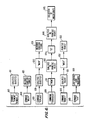
- a rule file 306 through 308 is collection rules arbitrarily organized by the creater of the file.
- Rule table 305 is a lookup table that is indexed by the name of the rules stored therein.
- the rule table 305 is an attribute of a rule base 301 that has in addition to the rules stored in rule table 305, a name 303 and other attributes 304 of the rule base.
- the all rule bases table 300 is a lookup table indexed by the name of the rule base.
- the all rule base table 300 is the top of the rule information hierarchy.
- the logic design data is partitioned into blocks, called model definitions 315 through 316.
- Any number of model definitions can be stored in the model definition table, a lookup table indexed by the model name.
- a model definition can contain a model instance list 318 that includes model instances 319 and 320 that are model instances of other model definitions. For any functional part type or structural body of a given name, only one model definition can exist. However, any functional part type or structural body can have 0 or more model instances.
- the attributes of the model definition are common to all of the instances associated therewith and, therefore need to be stored only with the model definition.
- the model definition contains "LIBRARY" information.
- the attributes of the model instances such as timing parameters and simulation values are unique to each model instance and, consequently, must be stored with the associated instance.
- Those model definitions with no model instances or for which a "LIBRARY" attribute is specified are considered primitive model definitions stored in table 315.
- the model definition table 314 is stored in a design table 312, the design table capable of possessing other attributes. Any number of designs 311 through 312 can be contained in the all design table 310.
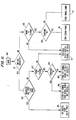
- Fig. 4 the general structure of the rule 40 used in the logic network synthesis is shown.
- the structure is created for each rule 40.
- a location in the file is reserved for the name field 41 of the rule.
- Another location is reserved for comments file 42 which are formal comments concerning the use of the rule.
- Antecedents field 43, consequences field 44 version field 45, history field 46 and sizewin field 47 are fields within the rule structure.
- the antecedent field 43 and the consequence field 44 are described below.
- the version field 45 includes version information from a host computer aided design (CAD) data management system when available or time_of_day and date information when available.
- the rule history field 46 is initially set to zero and is subsequently used to keep a running count of the number of times the associated rule is applied.
- CAD computer aided design
- a qualified object is database object at the end of an access chain for which the beginning is a current instance.
- a qualified object may also be a plurality of qualified objects.
- a primitive is taken as is without further database access (e.g. a number is a primitive object).
- count_of_inputs is N
- the qualified object 510 is followed by a verb 511 followed by a primitive object 512.
- the meaning of this field is that if the current instance has N inputs, then this antecedent will return a 'true' (T) when evaluated, otherwise, the antecedent will return a 'nil' when evaluated.
- the qualified object 520 is followed by a verb 521 which in turn is followed by a qualified object 522.
- the third example illustrates an adjective 530 followd by a qualified object 531, in turn followed by a verb 532, which in turn is followed by primitive object 533. This field is interpreted as follows, when any of the inputs of the current instance is not coupled to a signal, the antecedent will return a 'true' value.
- an adjective 540 is followed by a qualified object 541, in turn followed by a verb 542, which is in turn followed by a qualified object 543.
- a value ⁇ result ⁇ 550 is stored that is the result of a called procedure 551 with an arbitrary number of arguments 552, 553 et al. This procedure call permits LISP functions to be used by a rule antecedent field.
- the arguments 552, 553 et al. can be primitive objects or qualified objects.
- the name result can be used during the remainder of the rule antecedent field procedure and consequence field procedures to fetch the value stored under that name.
- the number of tags is not limited and all tag storage is erased when the antecedents portion of the rule is false or at the completion of the consequences portion of the rule. This type of antecedent always returns a 'true' (T) value, regardless of the value of the tag field.
- Fig. 6 the structure of the consequence field of the rule is illustrated by six examples.
- the command "remove” or "remove_if” 610 is used to remove one or more instances 611 from the instances of the current model definition.
- the "insert” command 620 is used to perform the reverse of the 'remove' command 610.
- the third example illustrates the 'replace' command 33. This command is combined with the 'remove' and the 'insert' command to remove one or more qualified model instance objects 631 and then to insert one or more model instance objects derived from equation form 633.
- FIG. 6 illustrates the form of the 'synthesize' command 640.
- This command is used for complex multibit synthesis in which the current instance operated up [on by the rule has the attributes of most significant bit and least significant bit, as is common in high level specifications of digitial designs.
- An example of such a device is a 32 bit incrementer, which can have a most significant bit of 31 and the least significant bit of 0.
- the keyword 'from' 641 Following the 'synthesize' command is the keyword 'from' 641, followed by access to the most significant bit 642.
- the most significant bit 642 is followed by the keyword 'to', followed by access to the least significant bit 644 and finally followed by a collection of rules 645.
- Fig. 6 identifies the form of the 'modify' command 650. This command is used to alter a database object by setting its value.
- the 'modify' keyword is followed by a qualified object 651, the qualified object being followed by the keyword 'with' 652.
- the keyword 'with' is then followed by a primitive object 653.
- the sixth exmaple of Fig. 6 uses the "LISP' keyword to permit entry of a LISP procedural expression 660. This procedural capability provides additional flexibility to modify the design database.
- a rule 712 is applied against an instance 706.
- the consequence portion of the rule contains either an 'insert' or a 'replace' command followed by the equation statement 713.
- the output forms of the equation statement refer to the second output 709 and first output 708 of the current model instance 706.
- the inputs of the equation refer to the inputs 705 which are 703 and 704 of the current model instance.
- Signal A 701 is coupled to the first input 703
- signal B 702 is coupled to the second input 704
- signal C 710 is coupled to the first output 708
- signal D 711 is coupled to the second output 701.
- the equation is interpreted to cause creation of a new model instance 721 which is an instance of model definition 727 with the name "Part_1" 728.
- the new instance is given outputs 722, 723 and 724 with couplings to the signals D and C 725 and 726.
- the order of the output signals has been reversed compared to the order of the current instances as required by the access ordering ('2nd-out', '1st-out') in the equation 713.
- the signals 725 and 736 are the same as the signals 711 and 710, although the pointers to/from the new ports 723 ad 724 have been added.
- the new instance is given an input group 720 with specific inputs 717 and 718 which have coupling to signals A and B 714 and 715.
- Signals A and B are found by getting the signals 701 and 702 coupled to the inputs 703, 704 and 705 of model instance 706.
- An additional input form "tie_hi” is names in the equation 713. This additional name referred to a signal names "tie_hi” 716. This signal is found by the function "find-signal' described below (i.e., in Fig. 11 and in Fig. 12).
- a third input 719 is created for this signal with the name "tie_hi".
- the equation itself refers directly to the names of signals or the implied access of signals of the port instances (inputs, outputs) relative to a current instance.
- one or more new instances are created with interfaces coupled to these same signals.
- FIG. 8 the insertion of design from a "nested” equation is shown.
- a rule 839 is interpreted against a current model instance 835.
- the current model instance 835 has inputs 834, 832 and 833, and one output 836 and 837.
- the consequence equation 840 indicates insertion of a tree of parts, Part_1 fed by Part_2.
- the output access form of the equation, 'OUTPUT' refers to the output is the signal 838 of outputs of the current model instance 735. Also, signal 738 is then coupled with the output of newly added parts for the access form 'OUTPUT' appearing on the left side of equation 740.
- the input access form of the equation 740 'INPUTS' implies the inputs of PARTS_2 are coupled to the signals 830 and 831 of the inputs of the current model instance.
- two model instances 846 and 852 are created.
- An internal signal 849 is generated for the coupling between the two model instances.
- a rule 961 with separate consequence statement 962 which can achieve the same result as the "nested equation" of Fig. 8 is shown.
- the rule creator or writer provides a local signal name "temp%” 962 as an input to Part_1 and an output of Part_2.
- the '%' character in the name identifies it as a local name.
- the name "temp%” is appended to a unique substring so that the resulting signal name in unique globally in the entire circuit design.
- “temp%” may be transformed to "xxtemp%” to accomplish the role of electrical coupling in the same manner as the signal "xx%” of Fig. 8.
- This method gives the rule writer some control over the naming and possible meaning of the new signal 849.
- the insertion also permits the use of the 'MODIFY' command statement to set parameters relative to the instance just inserted by the previous equation statement.
- the signal of selected port instance objects can be "erased" from a set of equation signals through the use of the 'ERASE' keyword, as shown in Fig. 10.
- a rule 980 is interpreted against a current model instance 976.
- a source instance 968 is connected through a path 969, 970, 971, 973 and 975 to the current instance 976.
- the equation 981 indicates the creation of a new instance 989 with inputs connected to the signals of the inputs of the current instance, 'J' and 'K', and the signals of the inputs of the source 968 of the current instance, 'H' and 'I', but not the signals 'J' of the outputs of the sources 968 of the current instance.
- FIG. 11 the flowchart of the access to the signals as specified by the equations is illustrated.
- An input form which is from the second, third, etc., items of an equation right side starts as a name 100.
- the name may have brackets ⁇ > identifying access to a significant bit of the prospective signal, in which case it follows decision 101 to 102. If the name consists only of a bit position access, an appropriate access expression is generated in step 105, cf U.S. Patent Application "Bitwise Implementation Mechanism for a Circuit Design Synthesis Procedure", cited supra.
- the name is not a string 103 and 108, it is assumed to be an access to a port instance object, and the data base access for the signal of the object is generated 110 as described in the U.S. Patent Application "Data Base Access Mechanism for Rules Utilized by a Synthesis Procedure for Logic Circuit Design". If it has bit brackets, is a string, and contains the character '%' 104, an expression is generated to find a bit significant signal of a local name with bit access 106. If it has bit brackets, is a string, and does not contain the character '%', an expression is generated to find a bit significant signal of an accessed object with bit access 107.
- brackets is a string, and contains the character '%' 109, and expression is generated to create a local signal whose name is derived from this name 111. If it does not have brackets, is a string, and does not contain '%' an expression is generated to find a global signal by this name.
- Fig. 12 the algorithm for interpretation of the signal access expressions is shown.
- Four types of signal access expressions exit.
- the other three methods derive a signal name, look for the signal in a table of all the signals in the current model 120. If the signal is there, return it 124, otherwise create a new signal 122 and place it in the signal table 123 and return it 124.
- the function 'find_signal' 116 uses the name as provided.
- the function 'syn-signal' 114 appends a local substring to the name to make this signal name unique to this rule and to the current design model.
- the function 'find-bit-signal' 115 can use any of the other three methods 113, 115 and 116 to obtain a root signal name, then obtains the value of the significant bit, and appends that in brackets ' ⁇ bit>' at the end of the name.
- signal names or data base objects representing signal names are ordered in the order that they appear in the schematic drawing of the model object.
- the procedure assumes that inputs are drawn at the top, left or bottom of the symbol, with counter-clockwise ordering.
- the procedure also assumes that outputs are drawn at the top, right or bottom of the symbol, with clockwise ordering.
- Most schematic symbols have inputs only on the left side and outputs only on their right side. It is a simple matter to derive the model definitions ordering from the drawing coordinates of the symbol. Because other CAD tools generally format pins of instances randomly by pin name/signal name match up, it is possible to sort the pins of instances from these tools into the model definitions order when an interface to such tools occurs.
- the rule writer in this invention when specifying a structual part of the operator to be inserted, need only name the part and signals to be coupled thereto in their drawing shape order.
- the basic equation format is similar to the software programming language ALGOL and uses nesting and function prefix notation similar to the programming language LISP.
- Simple LISP functions have the syntax: ( ⁇ function-name> ⁇ argument> ⁇ argument>...) where ⁇ function- name> refers to a LISP procedure name and ⁇ argument> is the name of a variable value passed to the procedure at its start.
- equation format of this invention while similar to some high-level programming languages in form, has an entirely different meaning and purpose.
- the equation format is used to describe the structural form of logic design data base objects and also their connectivity to one another.
- the format is used in the rule consequences to insert new model instance objects into a current design model.
- the format can also be used to add or modify attributes of any data base relative to the current instances or to the instances being inserted.
- ⁇ input-form> can be a signal name, a list of signal names, a data base access to a pin, or a data base access to a group of pins, or another ( ⁇ model-name> ⁇ input-form> ⁇ input-form> ...) in a LISP-like nest.
- ⁇ model-name> can be the name of a model definition which defines the functional, interface, size and other characteristics of either an abstract function or a technology part type.
- a signal name in the insertion equation of one rule matching a signal name in the insertion equation of another rule implies electrical connectivity.
- the signal of the accessed object is retrieved and used to connect to the interface model instance.
- the form indicated a signal name to begin with the name is looked up in a signal table. If it exists in that table, then the signal object pointed to by the table is retrieved and used. If the signal does not exist in the signal table, then a new signal is created, put in the signal table and used to connect to the interface port instances of the model instance at model instance creation time.
- model instance creation For each model instance creation, first the objects interface form of model instance, port instances, and signal is generated. Then the full logical design data base pointers are installed as described in the U.S. Patent Application entitled “Procedure and Data structure for synthesis and Transformation of Logic Circuit Designs” cited above.
- a 'MODIFY' command can be inserted to set data base attributes relative to the new instance, as described in the U.S. Patent Application entitled “Rule Structure for Synthesis of Logic Circuit Design", cited above.
- a data base access 'ERASE' keyword can be prepended to the name of a port instance object in an equation, indicating that the signal object at rule interpretation time is to be removed from the group of retrieved input or output signals at instance interface time.
Landscapes
- Engineering & Computer Science (AREA)
- Computer Hardware Design (AREA)
- Physics & Mathematics (AREA)
- Theoretical Computer Science (AREA)
- Evolutionary Computation (AREA)
- Geometry (AREA)
- General Engineering & Computer Science (AREA)
- General Physics & Mathematics (AREA)
- Design And Manufacture Of Integrated Circuits (AREA)
Applications Claiming Priority (2)
| Application Number | Priority Date | Filing Date | Title |
|---|---|---|---|
| US90751386A | 1986-09-12 | 1986-09-12 | |
| US907513 | 1986-09-12 |
Publications (2)
| Publication Number | Publication Date |
|---|---|
| EP0259703A2 true EP0259703A2 (de) | 1988-03-16 |
| EP0259703A3 EP0259703A3 (de) | 1990-09-19 |
Family
ID=25424226
Family Applications (1)
| Application Number | Title | Priority Date | Filing Date |
|---|---|---|---|
| EP19870112426 Withdrawn EP0259703A3 (de) | 1986-09-12 | 1987-08-26 | Regelstruktur zur Einfügung von neuen Elementen in einem Synthesisverfahren von Schaltungsentwurf |
Country Status (8)
| Country | Link |
|---|---|
| US (1) | US5452226A (de) |
| EP (1) | EP0259703A3 (de) |
| JP (1) | JPS63155266A (de) |
| AU (1) | AU7728187A (de) |
| DK (1) | DK473487A (de) |
| FI (1) | FI873920A7 (de) |
| IE (1) | IE872448L (de) |
| IL (1) | IL83698A (de) |
Families Citing this family (18)
| Publication number | Priority date | Publication date | Assignee | Title |
|---|---|---|---|---|
| WO2004077555A1 (ja) * | 1992-03-31 | 2004-09-10 | Yasuo Jimbo | Lsi設計部品データの管理装置 |
| US5625567A (en) * | 1993-11-12 | 1997-04-29 | Viewlogic Systems, Inc. | Electronic circuit design system and method with programmable addition and manipulation of logic elements surrounding terminals |
| US5764534A (en) * | 1994-10-13 | 1998-06-09 | Xilinx, Inc. | Method for providing placement information during design entry |
| WO1996036921A1 (en) * | 1995-05-19 | 1996-11-21 | 3Com Corporation | Method and apparatus for linking computer aided design databases with a numerical control machine database |
| US5805861A (en) * | 1995-08-29 | 1998-09-08 | Unisys Corporation | Method of stabilizing component and net names of integrated circuits in electronic design automation systems |
| US6173245B1 (en) * | 1995-10-18 | 2001-01-09 | Altera Corporation | Programmable logic array device design using parameterized logic modules |
| US5712794A (en) * | 1995-11-03 | 1998-01-27 | Motorola, Inc. | Automated method for adding attributes indentified on a schematic diagram to an integrated circuit layout |
| US5825661A (en) * | 1996-05-01 | 1998-10-20 | International Business Machines Corporation | Method and apparatus for automatic post-layout optimization of an integrated circuit |
| US6865524B1 (en) * | 1997-01-08 | 2005-03-08 | Trilogy Development Group, Inc. | Method and apparatus for attribute selection |
| US5991523A (en) * | 1997-03-18 | 1999-11-23 | Xilinx, Inc. | Method and system for HDL global signal simulation and verification |
| US5995730A (en) * | 1997-05-23 | 1999-11-30 | Lsi Logic Corporation | Method for generating format-independent electronic circuit representations |
| US5949993A (en) * | 1997-10-31 | 1999-09-07 | Production Languages Corporation | Method for the generation of ISA simulators and assemblers from a machine description |
| US7071952B1 (en) * | 1998-11-30 | 2006-07-04 | Actcon Control Ab | Method for inserting objects into a working area in a computer application |
| US6505328B1 (en) * | 1999-04-27 | 2003-01-07 | Magma Design Automation, Inc. | Method for storing multiple levels of design data in a common database |
| US6625789B2 (en) * | 2000-04-14 | 2003-09-23 | Hitachi, Ltd. | Computer-readable medium for recording interface specifications |
| US6813751B2 (en) * | 2002-07-16 | 2004-11-02 | International Business Machines Corporation | Creating standard VHDL test environments |
| TW201211808A (en) * | 2010-09-10 | 2012-03-16 | Hon Hai Prec Ind Co Ltd | System and method for checking electrical rules |
| US10810790B1 (en) * | 2013-02-28 | 2020-10-20 | TheMathWorks, Inc. | Identification and correction of temporal ages in separate signal paths of a graphical model |
Family Cites Families (12)
| Publication number | Priority date | Publication date | Assignee | Title |
|---|---|---|---|---|
| FR2245984B1 (de) * | 1973-09-27 | 1977-03-18 | Ibm | |
| UST935003I4 (en) * | 1974-02-19 | 1975-06-03 | Process for selecting circuits with optimum | |
| US4386403A (en) * | 1979-12-31 | 1983-05-31 | International Business Machines Corp. | System and method for LSI circuit analysis |
| US4377849A (en) * | 1980-12-29 | 1983-03-22 | International Business Machines Corporation | Macro assembler process for automated circuit design |
| US4441207A (en) * | 1982-01-19 | 1984-04-03 | Environmental Research Institute Of Michigan | Design rule checking using serial neighborhood processors |
| US4613940A (en) * | 1982-11-09 | 1986-09-23 | International Microelectronic Products | Method and structure for use in designing and building electronic systems in integrated circuits |
| US4584653A (en) * | 1983-03-22 | 1986-04-22 | Fujitsu Limited | Method for manufacturing a gate array integrated circuit device |
| JPS60114968A (ja) * | 1983-11-28 | 1985-06-21 | Hitachi Ltd | 推論システム |
| US4703435A (en) * | 1984-07-16 | 1987-10-27 | International Business Machines Corporation | Logic Synthesizer |
| EP0169576B1 (de) * | 1984-07-27 | 1990-12-19 | Hitachi, Ltd. | Verfahren und System zum Verstehen und Belegen von Schaltungsmustern |
| US4635208A (en) * | 1985-01-18 | 1987-01-06 | Hewlett-Packard Company | Computer-aided design of systems |
| JPH0668696B2 (ja) * | 1985-02-22 | 1994-08-31 | 株式会社日立製作所 | 挿入機用ncデータ作成方法 |
-
1987
- 1987-08-20 AU AU77281/87A patent/AU7728187A/en not_active Abandoned
- 1987-08-26 EP EP19870112426 patent/EP0259703A3/de not_active Withdrawn
- 1987-08-31 IL IL83698A patent/IL83698A/xx unknown
- 1987-09-10 FI FI873920A patent/FI873920A7/fi not_active Application Discontinuation
- 1987-09-11 IE IE872448A patent/IE872448L/xx unknown
- 1987-09-11 DK DK473487A patent/DK473487A/da not_active Application Discontinuation
- 1987-09-11 JP JP62226726A patent/JPS63155266A/ja active Pending
-
1991
- 1991-05-21 US US07/703,706 patent/US5452226A/en not_active Expired - Lifetime
Non-Patent Citations (2)
| Title |
|---|
| IEEE DESIGN & TEST OF COMPUTERS, vol. 2, no. 1, February 1985, pages 55-62, IEEE, New York, US; K.J. LIEBERHERR: "Toward a standard hardware description language" * |
| IEEE DESIGN & TEST OF COMPUTERS, vol. 2, no. 5, October 1985, pages 27-34, IEEE, New York, US; T. UEHARA: "A knowledge-based logic design system" * |
Also Published As
| Publication number | Publication date |
|---|---|
| JPS63155266A (ja) | 1988-06-28 |
| FI873920A0 (fi) | 1987-09-10 |
| FI873920L (fi) | 1988-03-13 |
| IL83698A (en) | 1992-06-21 |
| EP0259703A3 (de) | 1990-09-19 |
| IE872448L (en) | 1988-03-12 |
| AU7728187A (en) | 1988-03-17 |
| DK473487D0 (da) | 1987-09-11 |
| IL83698A0 (en) | 1988-01-31 |
| FI873920A7 (fi) | 1988-03-13 |
| US5452226A (en) | 1995-09-19 |
| DK473487A (da) | 1988-03-13 |
Similar Documents
| Publication | Publication Date | Title |
|---|---|---|
| EP0259703A2 (de) | Regelstruktur zur Einfügung von neuen Elementen in einem Synthesisverfahren von Schaltungsentwurf | |
| US5175696A (en) | Rule structure in a procedure for synthesis of logic circuits | |
| US5267175A (en) | Data base access mechanism for rules utilized by a synthesis procedure for logic circuit design | |
| US5197016A (en) | Integrated silicon-software compiler | |
| US5222029A (en) | Bitwise implementation mechanism for a circuit design synthesis procedure | |
| US6304790B1 (en) | System design/evaluation CAD system and program storage medium | |
| US5455775A (en) | Computer design system for mapping a logical hierarchy into a physical hierarchy | |
| US7062427B2 (en) | Batch editor for netlists described in a hardware description language | |
| US5568396A (en) | Identifying overconstraints using port abstraction graphs | |
| US5281558A (en) | Cloning method and system for hierarchical compaction | |
| US6192504B1 (en) | Methods and systems for functionally describing a digital hardware design and for converting a functional specification of same into a netlist | |
| WO2000065492A1 (en) | Method for storing multiple levels of design data in a common database | |
| US5548524A (en) | Expression promotion for hierarchical netlisting | |
| US5987239A (en) | Computer system and method for building a hardware description language representation of control logic for a complex digital system | |
| US20050039152A1 (en) | Timing path detailer | |
| Poulin | Integrated support for software reuse in computer-aided software engineering (CASE) | |
| Cyre et al. | Generating validation feedback for automatic interpretation of informal requirements | |
| Urban et al. | Constraint analysis: A tool for explaining the semantics of complex objects | |
| Carmona et al. | Synthesis of asynchronous hardware from petri nets | |
| Cyre et al. | Generating VHDL models from natural language descriptions. | |
| Duce et al. | Formal specification in the revision of GKS: an illustrative example | |
| Campbell et al. | STRICT: a design language for strongly typed recursive integrated circuits | |
| EP0267379A2 (de) | Zugriffsmechanismus zur Datenbank für die Regeln die in einem Synthesisverfahren verwendet werden zum Entwurf von logischen Schaltungen | |
| Davis et al. | A Verilog preprocessor for representing datapath components | |
| Gotlieb et al. | Data schemata based on directed graphs |
Legal Events
| Date | Code | Title | Description |
|---|---|---|---|
| PUAI | Public reference made under article 153(3) epc to a published international application that has entered the european phase |
Free format text: ORIGINAL CODE: 0009012 |
|
| AK | Designated contracting states |
Kind code of ref document: A2 Designated state(s): AT BE CH DE ES FR GB GR IT LI LU NL SE |
|
| PUAL | Search report despatched |
Free format text: ORIGINAL CODE: 0009013 |
|
| AK | Designated contracting states |
Kind code of ref document: A3 Designated state(s): AT BE CH DE ES FR GB GR IT LI LU NL SE |
|
| 17P | Request for examination filed |
Effective date: 19910319 |
|
| 17Q | First examination report despatched |
Effective date: 19920714 |
|
| STAA | Information on the status of an ep patent application or granted ep patent |
Free format text: STATUS: THE APPLICATION IS DEEMED TO BE WITHDRAWN |
|
| 18D | Application deemed to be withdrawn |
Effective date: 19940305 |
|
| RIN1 | Information on inventor provided before grant (corrected) |
Inventor name: HOOPER, DONALD F. Inventor name: KUNDU, SNEHAMAY |