EP0259079A2 - Verfahren zum Bilden von geformten Gegenständen aus mikroporösem Wärmeisolierendem Material - Google Patents
Verfahren zum Bilden von geformten Gegenständen aus mikroporösem Wärmeisolierendem Material Download PDFInfo
- Publication number
- EP0259079A2 EP0259079A2 EP87307451A EP87307451A EP0259079A2 EP 0259079 A2 EP0259079 A2 EP 0259079A2 EP 87307451 A EP87307451 A EP 87307451A EP 87307451 A EP87307451 A EP 87307451A EP 0259079 A2 EP0259079 A2 EP 0259079A2
- Authority
- EP
- European Patent Office
- Prior art keywords
- mould
- intimate mixture
- compacted
- die
- walls
- Prior art date
- Legal status (The legal status is an assumption and is not a legal conclusion. Google has not performed a legal analysis and makes no representation as to the accuracy of the status listed.)
- Withdrawn
Links
Images
Classifications
-
- B—PERFORMING OPERATIONS; TRANSPORTING
- B28—WORKING CEMENT, CLAY, OR STONE
- B28B—SHAPING CLAY OR OTHER CERAMIC COMPOSITIONS; SHAPING SLAG; SHAPING MIXTURES CONTAINING CEMENTITIOUS MATERIAL, e.g. PLASTER
- B28B23/00—Arrangements specially adapted for the production of shaped articles with elements wholly or partly embedded in the moulding material; Production of reinforced objects
- B28B23/0018—Producing metal-clad stones, such as oven stones
-
- B—PERFORMING OPERATIONS; TRANSPORTING
- B28—WORKING CEMENT, CLAY, OR STONE
- B28B—SHAPING CLAY OR OTHER CERAMIC COMPOSITIONS; SHAPING SLAG; SHAPING MIXTURES CONTAINING CEMENTITIOUS MATERIAL, e.g. PLASTER
- B28B3/00—Producing shaped articles from the material by using presses; Presses specially adapted therefor
- B28B3/02—Producing shaped articles from the material by using presses; Presses specially adapted therefor wherein a ram exerts pressure on the material in a moulding space; Ram heads of special form
-
- B—PERFORMING OPERATIONS; TRANSPORTING
- B28—WORKING CEMENT, CLAY, OR STONE
- B28B—SHAPING CLAY OR OTHER CERAMIC COMPOSITIONS; SHAPING SLAG; SHAPING MIXTURES CONTAINING CEMENTITIOUS MATERIAL, e.g. PLASTER
- B28B7/00—Moulds; Cores; Mandrels
- B28B7/40—Moulds; Cores; Mandrels characterised by means for modifying the properties of the moulding material
-
- C—CHEMISTRY; METALLURGY
- C04—CEMENTS; CONCRETE; ARTIFICIAL STONE; CERAMICS; REFRACTORIES
- C04B—LIME, MAGNESIA; SLAG; CEMENTS; COMPOSITIONS THEREOF, e.g. MORTARS, CONCRETE OR LIKE BUILDING MATERIALS; ARTIFICIAL STONE; CERAMICS; REFRACTORIES; TREATMENT OF NATURAL STONE
- C04B40/00—Processes, in general, for influencing or modifying the properties of mortars, concrete or artificial stone compositions, e.g. their setting or hardening ability
- C04B40/0071—Processes, in general, for influencing or modifying the properties of mortars, concrete or artificial stone compositions, e.g. their setting or hardening ability making use of a rise in pressure
Definitions
- the present invention relates to a method of moulding shaped articles of microporous thermal insulation material.
- Microporous thermal insulation materials are produced by applying pressure to an intimate mixture of finely divided silica, an infra-red opacifier and optionally a reinforcing fibre. Such materials can be formed into simple shapes by confining the intimate mixture in a mould and compacting it with a die. A profile may be provided in the mould or the die to produce the desired shape, but it is difficult accurately to control the dimensions of the shaped insulation article so produced.
- Microporous thermal insulation materials are difficult to handle because of inherent resilience which is apparent when a shaped insulation article is removed from a mould in that the shape of the article is not identical with the profile of the mould. This is because the compacted microporous material expands when the applied moulding pressure is released.
- Allowances can be made in the shape of the mould tools to enable the desired shaped article to be formed, but difficulties remain in removing the shaped article from the mould.
- the shaped insulation article can be formed by temporarily closing one end of the tube, introducing a charge of the intimate mixture, and applying pressure to the die so as to form the disc.
- the disc can then be removed from the tube by opening the end of the tube and pushing the disc from the tube with the die. Nevertheless, the disc can be seen to increase in diameter as it leaves the tube and small cracks may form around the edge of the disc, but the overall result is generally satisfactory.
- the above-described technique can be improved by employing a tube which is constructed from two or more parts and which can be disassembled to free the shaped insulation article from the mould.
- the mould may be a simple rectangular construction comprising four upright walls connected to form an open box and the die may be a rectangular element which is slidable within the mould in the manner of an internally fitting lid.
- the mould is charged with the intimate mixture which is then compacted within the mould by applying pressure by way of the die so as to form a compacted slab of microporous thermal insulation material.
- the compacted insulation material expands, even though it is still within the mould, to form a domed shape which cracks and distorts, thus making it impossible to remove the shaped insulation article from the mould without damaging it.
- One solution to this problem involves modifying the composition of the intimate mixture in order to eliminate as far as possible the characteristic expansion which occurs when the forming pressure is removed from the compacted block. This may be accomplished by incorporating additives in the intimate mixture which improve self-bonding of the constituents of the mixture, which additive may or may not be removed at a latter stage in the manufacture of the shaped insulation article. Unfortunately, we have found that this solution has the disadvantage of reducing the performance of the shaped insulation article by increasing the thermal conductivity of the microporous thermal insulation material.
- a method of moulding shaped articles of microporous thermal insulation material comprises the steps of: providing a mould which is dimensioned so as to be smaller by a predetermined amount than the corresponding dimensions of the desired shaped article, which mould comprises a base and side walls; charging a predetermined amount of an intimate mixture of a microporous thermal insulation material into the mould; compacting the intimate mixture within the mould by means of a die which is urged towards the base of the mould within the area defined by the side walls; removing at least a part of the side walls of the mould while the compacted intimate mixture remains under compression due to the urging of the die towards the base of the mould; and releasing the urging of the die towards the base of the mould so as to allow the compacted intimate mixture to expand freely;
- the side walls of the mould may be removed by dismantling the walls. Automatically, the side walls may be removed by withdrawing the walls.
- the mould may include a tray into which the intimate mixture is compacted, the walls of the mould extending into the tray such that when the walls are removed the compacted intimate mixture expands to abut against edges of the tray.
- the edges of the tray may be formed with a rim, the intimate mixture expanding to fill the gap between the rim and the base of the tray.
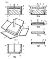
- a simple rectangular slab can be moulded by confining a charge 1 of an intimate mixture of finely divided silica such as pyrogenic silica, an infra-red opacified and a reinforcing fibre within a box 2 which comprises four walls 3 arranged on a base 4.
- the charge 1 of intimate mixture is compacted by applying pressure to a die 5.
- Doming of the compacted slab is avoided by the means shown in Figure 2 or Figure 3.
- the mould can be disassembled by removing the walls 3 while the die 5 still applies pressure to the slab 6. After the walls 3 have been removed, the pressure on the die 5 may be released to leave a perfectly formed slab 6.
- the mould can be removed by withdrawing the side walls 3 as a single unit upwardly beyond the limits the slab 6 while the die 5 still applies pressure to the slab. Once again, pressure on the die 5 may be released once the walls 3 have been removed to leave a perfectly formed slab 6.
- Figures 4, 5 and 6 illustrate how a slab 11 may be supported in a metal tray 12.
- the metal tray forms the base of the mould with the walls 13 configured to fit closely against the side walls of the tray 12.
- the walls 13 are arranged such that the dimensions of the slab 11 are initially a predetermined amount smaller than the dimensions of the tray.
- the lower faces of the walls 13 are provided with recesses 14 so that the walls extend downwardly substantially to the surface of the tray 12.
- a charge 15 of intimate mixture as described about is confined within the mould and is compacted by applying pressure to a die 16.
- Figure 5 shows that when the intimate mixture has been compacted to form slab 11 the walls 13 are removed while the die 16 still applies pressure to the slab 11.
- the removal of the walls may be by either of the methods described above with reference to Figures 2 and 3.
- the removal of the walls 13 results in a gap 17 being formed temporarily between the edges of the slab 11 and the side walls of the tray 12.
- the compacted insulation material quickly expands to abut against the side walls of the tray.
- the die 16 may then be removed to leave slab 11 firmly held in tray 12 as can be seen in Figure 6.
- the walls of the tray may be shaped as can be seen in Figure 7 so that the slab is supported by a rim 18. This can be achieved because of the expansion of the compacted insulation material subsequent to the removal of the walls of the mould.
- the provision of the rim 18 can assist in certain circumstances in improving the handleability of the product.
- the present invention has been described with reference to the production of a shaped article in the form of a simple rectangular slab, the shape of the article is not restricted to such a slab and many other shapes can be produced. Further, although the method according to the present invention is most useful where the shaped article has relatively large dimensions, it can also be employed where the shaped article has relatively small dimensions.
Landscapes
- Engineering & Computer Science (AREA)
- Chemical & Material Sciences (AREA)
- Ceramic Engineering (AREA)
- Manufacturing & Machinery (AREA)
- Mechanical Engineering (AREA)
- Materials Engineering (AREA)
- Structural Engineering (AREA)
- Organic Chemistry (AREA)
- Casting Or Compression Moulding Of Plastics Or The Like (AREA)
- Thermal Insulation (AREA)
- Containers Having Bodies Formed In One Piece (AREA)
Applications Claiming Priority (2)
| Application Number | Priority Date | Filing Date | Title |
|---|---|---|---|
| GB8621204 | 1986-09-02 | ||
| GB868621204A GB8621204D0 (en) | 1986-09-02 | 1986-09-02 | Moulding shaped articles |
Publications (2)
| Publication Number | Publication Date |
|---|---|
| EP0259079A2 true EP0259079A2 (de) | 1988-03-09 |
| EP0259079A3 EP0259079A3 (de) | 1989-01-11 |
Family
ID=10603587
Family Applications (1)
| Application Number | Title | Priority Date | Filing Date |
|---|---|---|---|
| EP87307451A Withdrawn EP0259079A3 (de) | 1986-09-02 | 1987-08-24 | Verfahren zum Bilden von geformten Gegenständen aus mikroporösem Wärmeisolierendem Material |
Country Status (3)
| Country | Link |
|---|---|
| EP (1) | EP0259079A3 (de) |
| JP (1) | JPS6367498A (de) |
| GB (1) | GB8621204D0 (de) |
Cited By (2)
| Publication number | Priority date | Publication date | Assignee | Title |
|---|---|---|---|---|
| EP0368529A1 (de) * | 1988-11-08 | 1990-05-16 | Micropore International Limited | Paneele aus wärmedämmendem Material |
| CN113858633A (zh) * | 2021-09-15 | 2021-12-31 | 浙江松华新材股份有限公司 | 一种聚四氟乙烯板材连续成型设备及方法 |
Families Citing this family (1)
| Publication number | Priority date | Publication date | Assignee | Title |
|---|---|---|---|---|
| DE4322108C2 (de) * | 1992-07-03 | 2001-08-09 | Toyoda Gosei Kk | Verstärkte Polypropylenharzmischung und daraus hergestellte Radkappe |
Family Cites Families (3)
| Publication number | Priority date | Publication date | Assignee | Title |
|---|---|---|---|---|
| GB1328960A (en) * | 1971-07-29 | 1973-09-05 | Ciarrapico J O | Method of and apparatus for dry-pressing pottery |
| GB1474893A (en) * | 1975-07-16 | 1977-05-25 | Bettonica L | Hydraulic press particularly for the moulding of tiles and plates of ceramic materials |
| GB8506505D0 (en) * | 1985-03-13 | 1985-04-17 | Micropore International Ltd | Manufacturing thermally insulating body |
-
1986
- 1986-09-02 GB GB868621204A patent/GB8621204D0/en active Pending
-
1987
- 1987-08-24 EP EP87307451A patent/EP0259079A3/de not_active Withdrawn
- 1987-09-01 JP JP21654487A patent/JPS6367498A/ja active Pending
Cited By (2)
| Publication number | Priority date | Publication date | Assignee | Title |
|---|---|---|---|---|
| EP0368529A1 (de) * | 1988-11-08 | 1990-05-16 | Micropore International Limited | Paneele aus wärmedämmendem Material |
| CN113858633A (zh) * | 2021-09-15 | 2021-12-31 | 浙江松华新材股份有限公司 | 一种聚四氟乙烯板材连续成型设备及方法 |
Also Published As
| Publication number | Publication date |
|---|---|
| EP0259079A3 (de) | 1989-01-11 |
| GB8621204D0 (en) | 1986-10-08 |
| JPS6367498A (ja) | 1988-03-26 |
Similar Documents
| Publication | Publication Date | Title |
|---|---|---|
| EP0197630A3 (de) | Verfahren zur Herstellung einer ins Ohr passenden akustischen Hörhilfe | |
| EP0390151A3 (de) | Verfahren zum Herstellen einer Glasscheibe mit einer Abdichtung | |
| CA2150312A1 (en) | Casting Method with Improved Resin Core Removing Step and Apparatus for Performing the Method | |
| EP0259079A2 (de) | Verfahren zum Bilden von geformten Gegenständen aus mikroporösem Wärmeisolierendem Material | |
| US1554697A (en) | Manufacture of hollow articles | |
| GB2195575A (en) | Method of moulding articles of microporous thermal insulation material | |
| CA1061972A (en) | Method of and apparatus for moulding shaped objects | |
| JP2692165B2 (ja) | ディンプルプレートの成形方法 | |
| US11598019B2 (en) | Crucible-supporting pedestal, quartz crucible-supporting device, and method for producing silicon single crystal | |
| CA1144348A (en) | Moulding tool | |
| SU1135652A1 (ru) | Пустотообразователь | |
| EP0143954A3 (en) | Process for manufacturing mould parts according to the cold-box method, mould part formed and moulding apparatus used | |
| SU1675978A1 (ru) | Способ изготовлени волноводной нагрузки | |
| JPS59109341A (ja) | 螺子孔あきプレ−ト片面へのゴムシ−ル体成形法 | |
| CA1152298A (en) | Method for casting of a concrete base for a column and for stripping the form from said base | |
| JPS584650Y2 (ja) | 空胴コンクリ−トブロツク成形型枠の中子金具 | |
| AU6488980A (en) | Ingot mould comprising a hot-top positioned inside the upper part of the mould and process for manufacturing said mould | |
| JPH0318162Y2 (de) | ||
| JPS6011028A (ja) | 床暖房パネル及びその製造方法 | |
| JPH0235384Y2 (de) | ||
| JPS54159712A (en) | Scroll molding method for scroll compressor | |
| JPS6013619Y2 (ja) | ポリウレタン成形用金型 | |
| AU1604597A (en) | Method for the manufacture of concrete products | |
| EP3890934A1 (de) | Verfahren zur vermeidung von gratbildung beim entformen von rekonstruiertem stein und zierplatten und nach diesem verfahren erhaltene fertigprodukte | |
| EP0245534A3 (de) | Verfahren und Vorrichtung zum Herstellen einer Abreissverschlusskappe für Behälter |
Legal Events
| Date | Code | Title | Description |
|---|---|---|---|
| PUAI | Public reference made under article 153(3) epc to a published international application that has entered the european phase |
Free format text: ORIGINAL CODE: 0009012 |
|
| AK | Designated contracting states |
Kind code of ref document: A2 Designated state(s): AT BE CH DE ES FR GB IT LI NL SE |
|
| PUAL | Search report despatched |
Free format text: ORIGINAL CODE: 0009013 |
|
| AK | Designated contracting states |
Kind code of ref document: A3 Designated state(s): AT BE CH DE ES FR GB IT LI NL SE |
|
| STAA | Information on the status of an ep patent application or granted ep patent |
Free format text: STATUS: THE APPLICATION IS DEEMED TO BE WITHDRAWN |
|
| 18D | Application deemed to be withdrawn |
Effective date: 19890712 |
|
| RIN1 | Information on inventor provided before grant (corrected) |
Inventor name: HUGHES, JOHN THOMAS |