EP0259013B1 - Portable controlled release osmotic infusion device - Google Patents
Portable controlled release osmotic infusion device Download PDFInfo
- Publication number
- EP0259013B1 EP0259013B1 EP87306903A EP87306903A EP0259013B1 EP 0259013 B1 EP0259013 B1 EP 0259013B1 EP 87306903 A EP87306903 A EP 87306903A EP 87306903 A EP87306903 A EP 87306903A EP 0259013 B1 EP0259013 B1 EP 0259013B1
- Authority
- EP
- European Patent Office
- Prior art keywords
- drug
- containing chamber
- seal
- semipermeable membrane
- pump
- Prior art date
- Legal status (The legal status is an assumption and is not a legal conclusion. Google has not performed a legal analysis and makes no representation as to the accuracy of the status listed.)
- Expired - Lifetime
Links
- 230000003204 osmotic effect Effects 0.000 title claims abstract description 31
- 238000001802 infusion Methods 0.000 title claims abstract description 15
- 238000013270 controlled release Methods 0.000 title claims abstract description 11
- 239000003814 drug Substances 0.000 claims abstract description 63
- 229940079593 drug Drugs 0.000 claims abstract description 61
- 239000012528 membrane Substances 0.000 claims abstract description 35
- 239000011888 foil Substances 0.000 claims abstract description 17
- 230000003213 activating effect Effects 0.000 claims abstract description 14
- 239000002904 solvent Substances 0.000 claims abstract description 12
- 230000006866 deterioration Effects 0.000 claims abstract description 4
- 230000007246 mechanism Effects 0.000 claims description 23
- 238000005086 pumping Methods 0.000 claims description 20
- 239000012530 fluid Substances 0.000 claims description 14
- 230000009471 action Effects 0.000 claims description 8
- 229920001971 elastomer Polymers 0.000 claims description 8
- 229910052751 metal Inorganic materials 0.000 claims description 6
- 239000002184 metal Substances 0.000 claims description 6
- 239000005060 rubber Substances 0.000 claims description 6
- 238000003860 storage Methods 0.000 claims description 6
- 239000000729 antidote Substances 0.000 claims description 4
- 230000004913 activation Effects 0.000 claims description 3
- 239000007787 solid Substances 0.000 claims description 3
- 229920001184 polypeptide Polymers 0.000 claims description 2
- 102000004196 processed proteins & peptides Human genes 0.000 claims description 2
- 108090000765 processed proteins & peptides Proteins 0.000 claims description 2
- 231100000167 toxic agent Toxicity 0.000 claims description 2
- 239000003440 toxic substance Substances 0.000 claims description 2
- 238000004519 manufacturing process Methods 0.000 abstract description 4
- XLYOFNOQVPJJNP-UHFFFAOYSA-N water Substances O XLYOFNOQVPJJNP-UHFFFAOYSA-N 0.000 description 31
- 235000002639 sodium chloride Nutrition 0.000 description 28
- 150000003839 salts Chemical class 0.000 description 25
- 239000000243 solution Substances 0.000 description 10
- 239000000463 material Substances 0.000 description 8
- 229910052782 aluminium Inorganic materials 0.000 description 6
- XAGFODPZIPBFFR-UHFFFAOYSA-N aluminium Chemical compound [Al] XAGFODPZIPBFFR-UHFFFAOYSA-N 0.000 description 6
- 230000008901 benefit Effects 0.000 description 6
- 230000037452 priming Effects 0.000 description 6
- 229920002301 cellulose acetate Polymers 0.000 description 5
- 238000002347 injection Methods 0.000 description 5
- 239000007924 injection Substances 0.000 description 5
- 238000000034 method Methods 0.000 description 5
- 238000002560 therapeutic procedure Methods 0.000 description 5
- PEDCQBHIVMGVHV-UHFFFAOYSA-N Glycerine Chemical compound OCC(O)CO PEDCQBHIVMGVHV-UHFFFAOYSA-N 0.000 description 4
- FAPWRFPIFSIZLT-UHFFFAOYSA-M Sodium chloride Chemical compound [Na+].[Cl-] FAPWRFPIFSIZLT-UHFFFAOYSA-M 0.000 description 4
- 239000012190 activator Substances 0.000 description 4
- 239000003795 chemical substances by application Substances 0.000 description 4
- 230000000881 depressing effect Effects 0.000 description 4
- NOESYZHRGYRDHS-UHFFFAOYSA-N insulin Chemical compound N1C(=O)C(NC(=O)C(CCC(N)=O)NC(=O)C(CCC(O)=O)NC(=O)C(C(C)C)NC(=O)C(NC(=O)CN)C(C)CC)CSSCC(C(NC(CO)C(=O)NC(CC(C)C)C(=O)NC(CC=2C=CC(O)=CC=2)C(=O)NC(CCC(N)=O)C(=O)NC(CC(C)C)C(=O)NC(CCC(O)=O)C(=O)NC(CC(N)=O)C(=O)NC(CC=2C=CC(O)=CC=2)C(=O)NC(CSSCC(NC(=O)C(C(C)C)NC(=O)C(CC(C)C)NC(=O)C(CC=2C=CC(O)=CC=2)NC(=O)C(CC(C)C)NC(=O)C(C)NC(=O)C(CCC(O)=O)NC(=O)C(C(C)C)NC(=O)C(CC(C)C)NC(=O)C(CC=2NC=NC=2)NC(=O)C(CO)NC(=O)CNC2=O)C(=O)NCC(=O)NC(CCC(O)=O)C(=O)NC(CCCNC(N)=N)C(=O)NCC(=O)NC(CC=3C=CC=CC=3)C(=O)NC(CC=3C=CC=CC=3)C(=O)NC(CC=3C=CC(O)=CC=3)C(=O)NC(C(C)O)C(=O)N3C(CCC3)C(=O)NC(CCCCN)C(=O)NC(C)C(O)=O)C(=O)NC(CC(N)=O)C(O)=O)=O)NC(=O)C(C(C)CC)NC(=O)C(CO)NC(=O)C(C(C)O)NC(=O)C1CSSCC2NC(=O)C(CC(C)C)NC(=O)C(NC(=O)C(CCC(N)=O)NC(=O)C(CC(N)=O)NC(=O)C(NC(=O)C(N)CC=1C=CC=CC=1)C(C)C)CC1=CN=CN1 NOESYZHRGYRDHS-UHFFFAOYSA-N 0.000 description 4
- 239000012266 salt solution Substances 0.000 description 4
- 206010020751 Hypersensitivity Diseases 0.000 description 3
- 239000013543 active substance Substances 0.000 description 3
- 229940075522 antidotes Drugs 0.000 description 3
- 238000011161 development Methods 0.000 description 3
- 238000012377 drug delivery Methods 0.000 description 3
- 230000000694 effects Effects 0.000 description 3
- 229920000126 latex Polymers 0.000 description 3
- 230000007774 longterm Effects 0.000 description 3
- 230000005012 migration Effects 0.000 description 3
- 238000013508 migration Methods 0.000 description 3
- 238000011282 treatment Methods 0.000 description 3
- CSCPPACGZOOCGX-UHFFFAOYSA-N Acetone Chemical compound CC(C)=O CSCPPACGZOOCGX-UHFFFAOYSA-N 0.000 description 2
- 102000004877 Insulin Human genes 0.000 description 2
- 108090001061 Insulin Proteins 0.000 description 2
- CSNNHWWHGAXBCP-UHFFFAOYSA-L Magnesium sulfate Chemical compound [Mg+2].[O-][S+2]([O-])([O-])[O-] CSNNHWWHGAXBCP-UHFFFAOYSA-L 0.000 description 2
- WCUXLLCKKVVCTQ-UHFFFAOYSA-M Potassium chloride Chemical compound [Cl-].[K+] WCUXLLCKKVVCTQ-UHFFFAOYSA-M 0.000 description 2
- 241000220317 Rosa Species 0.000 description 2
- 229920005549 butyl rubber Polymers 0.000 description 2
- 238000005266 casting Methods 0.000 description 2
- 239000000806 elastomer Substances 0.000 description 2
- 235000011187 glycerol Nutrition 0.000 description 2
- 238000002513 implantation Methods 0.000 description 2
- 229940125396 insulin Drugs 0.000 description 2
- 230000004048 modification Effects 0.000 description 2
- 238000012986 modification Methods 0.000 description 2
- 230000002572 peristaltic effect Effects 0.000 description 2
- 230000035699 permeability Effects 0.000 description 2
- 230000002035 prolonged effect Effects 0.000 description 2
- 229920006395 saturated elastomer Polymers 0.000 description 2
- 239000011780 sodium chloride Substances 0.000 description 2
- 229910001220 stainless steel Inorganic materials 0.000 description 2
- 239000010935 stainless steel Substances 0.000 description 2
- 230000002459 sustained effect Effects 0.000 description 2
- 231100000331 toxic Toxicity 0.000 description 2
- 230000002588 toxic effect Effects 0.000 description 2
- FDKXTQMXEQVLRF-ZHACJKMWSA-N (E)-dacarbazine Chemical compound CN(C)\N=N\c1[nH]cnc1C(N)=O FDKXTQMXEQVLRF-ZHACJKMWSA-N 0.000 description 1
- 208000035473 Communicable disease Diseases 0.000 description 1
- HTTJABKRGRZYRN-UHFFFAOYSA-N Heparin Chemical compound OC1C(NC(=O)C)C(O)OC(COS(O)(=O)=O)C1OC1C(OS(O)(=O)=O)C(O)C(OC2C(C(OS(O)(=O)=O)C(OC3C(C(O)C(O)C(O3)C(O)=O)OS(O)(=O)=O)C(CO)O2)NS(O)(=O)=O)C(C(O)=O)O1 HTTJABKRGRZYRN-UHFFFAOYSA-N 0.000 description 1
- 102000014150 Interferons Human genes 0.000 description 1
- 108010050904 Interferons Proteins 0.000 description 1
- 102000000588 Interleukin-2 Human genes 0.000 description 1
- 108010002350 Interleukin-2 Proteins 0.000 description 1
- 229920000459 Nitrile rubber Polymers 0.000 description 1
- PMZURENOXWZQFD-UHFFFAOYSA-L Sodium Sulfate Chemical compound [Na+].[Na+].[O-]S([O-])(=O)=O PMZURENOXWZQFD-UHFFFAOYSA-L 0.000 description 1
- 239000004809 Teflon Substances 0.000 description 1
- 229920006362 Teflon® Polymers 0.000 description 1
- 238000010521 absorption reaction Methods 0.000 description 1
- 239000000853 adhesive Substances 0.000 description 1
- 230000001070 adhesive effect Effects 0.000 description 1
- 208000026935 allergic disease Diseases 0.000 description 1
- 230000007815 allergy Effects 0.000 description 1
- 210000001124 body fluid Anatomy 0.000 description 1
- 239000010839 body fluid Substances 0.000 description 1
- MTAZNLWOLGHBHU-UHFFFAOYSA-N butadiene-styrene rubber Chemical compound C=CC=C.C=CC1=CC=CC=C1 MTAZNLWOLGHBHU-UHFFFAOYSA-N 0.000 description 1
- 229920002678 cellulose Polymers 0.000 description 1
- 229920006217 cellulose acetate butyrate Polymers 0.000 description 1
- 229920001727 cellulose butyrate Polymers 0.000 description 1
- 229920003086 cellulose ether Polymers 0.000 description 1
- 230000002925 chemical effect Effects 0.000 description 1
- 239000002575 chemical warfare agent Substances 0.000 description 1
- 238000011340 continuous therapy Methods 0.000 description 1
- 229920001577 copolymer Polymers 0.000 description 1
- 230000000994 depressogenic effect Effects 0.000 description 1
- 206010012601 diabetes mellitus Diseases 0.000 description 1
- 238000002651 drug therapy Methods 0.000 description 1
- 239000013013 elastic material Substances 0.000 description 1
- 229920006332 epoxy adhesive Polymers 0.000 description 1
- 150000002170 ethers Chemical class 0.000 description 1
- 230000037406 food intake Effects 0.000 description 1
- 239000011521 glass Substances 0.000 description 1
- 239000000122 growth hormone Substances 0.000 description 1
- 229960002897 heparin Drugs 0.000 description 1
- 229920000669 heparin Polymers 0.000 description 1
- 239000005556 hormone Substances 0.000 description 1
- 229940088597 hormone Drugs 0.000 description 1
- 239000000017 hydrogel Substances 0.000 description 1
- 230000002209 hydrophobic effect Effects 0.000 description 1
- 238000005213 imbibition Methods 0.000 description 1
- 230000006872 improvement Effects 0.000 description 1
- 230000000977 initiatory effect Effects 0.000 description 1
- 238000009434 installation Methods 0.000 description 1
- 229940079322 interferon Drugs 0.000 description 1
- 238000001990 intravenous administration Methods 0.000 description 1
- 229910052943 magnesium sulfate Inorganic materials 0.000 description 1
- 235000019341 magnesium sulphate Nutrition 0.000 description 1
- 238000007567 mass-production technique Methods 0.000 description 1
- 150000002739 metals Chemical class 0.000 description 1
- 231100000344 non-irritating Toxicity 0.000 description 1
- 239000008177 pharmaceutical agent Substances 0.000 description 1
- 239000004033 plastic Substances 0.000 description 1
- 239000004417 polycarbonate Substances 0.000 description 1
- 229920000515 polycarbonate Polymers 0.000 description 1
- 229920001195 polyisoprene Polymers 0.000 description 1
- 229920000098 polyolefin Polymers 0.000 description 1
- 239000001103 potassium chloride Substances 0.000 description 1
- 235000011164 potassium chloride Nutrition 0.000 description 1
- 239000003380 propellant Substances 0.000 description 1
- 230000001681 protective effect Effects 0.000 description 1
- 102000004169 proteins and genes Human genes 0.000 description 1
- 108090000623 proteins and genes Proteins 0.000 description 1
- 230000009467 reduction Effects 0.000 description 1
- 239000003488 releasing hormone Substances 0.000 description 1
- 238000011160 research Methods 0.000 description 1
- 230000004044 response Effects 0.000 description 1
- 238000012552 review Methods 0.000 description 1
- 229910052938 sodium sulfate Inorganic materials 0.000 description 1
- 235000011152 sodium sulphate Nutrition 0.000 description 1
- 125000006850 spacer group Chemical group 0.000 description 1
- 239000012086 standard solution Substances 0.000 description 1
- 229920003048 styrene butadiene rubber Polymers 0.000 description 1
- 238000007920 subcutaneous administration Methods 0.000 description 1
- 239000000126 substance Substances 0.000 description 1
- 230000009885 systemic effect Effects 0.000 description 1
- 239000010409 thin film Substances 0.000 description 1
- 238000001771 vacuum deposition Methods 0.000 description 1
Images




Classifications
-
- A—HUMAN NECESSITIES
- A61—MEDICAL OR VETERINARY SCIENCE; HYGIENE
- A61M—DEVICES FOR INTRODUCING MEDIA INTO, OR ONTO, THE BODY; DEVICES FOR TRANSDUCING BODY MEDIA OR FOR TAKING MEDIA FROM THE BODY; DEVICES FOR PRODUCING OR ENDING SLEEP OR STUPOR
- A61M5/00—Devices for bringing media into the body in a subcutaneous, intra-vascular or intramuscular way; Accessories therefor, e.g. filling or cleaning devices, arm-rests
- A61M5/14—Infusion devices, e.g. infusing by gravity; Blood infusion; Accessories therefor
- A61M5/142—Pressure infusion, e.g. using pumps
- A61M5/145—Pressure infusion, e.g. using pumps using pressurised reservoirs, e.g. pressurised by means of pistons
-
- A—HUMAN NECESSITIES
- A61—MEDICAL OR VETERINARY SCIENCE; HYGIENE
- A61M—DEVICES FOR INTRODUCING MEDIA INTO, OR ONTO, THE BODY; DEVICES FOR TRANSDUCING BODY MEDIA OR FOR TAKING MEDIA FROM THE BODY; DEVICES FOR PRODUCING OR ENDING SLEEP OR STUPOR
- A61M5/00—Devices for bringing media into the body in a subcutaneous, intra-vascular or intramuscular way; Accessories therefor, e.g. filling or cleaning devices, arm-rests
- A61M5/14—Infusion devices, e.g. infusing by gravity; Blood infusion; Accessories therefor
- A61M5/142—Pressure infusion, e.g. using pumps
- A61M5/145—Pressure infusion, e.g. using pumps using pressurised reservoirs, e.g. pressurised by means of pistons
- A61M2005/14513—Pressure infusion, e.g. using pumps using pressurised reservoirs, e.g. pressurised by means of pistons with secondary fluid driving or regulating the infusion
-
- A—HUMAN NECESSITIES
- A61—MEDICAL OR VETERINARY SCIENCE; HYGIENE
- A61M—DEVICES FOR INTRODUCING MEDIA INTO, OR ONTO, THE BODY; DEVICES FOR TRANSDUCING BODY MEDIA OR FOR TAKING MEDIA FROM THE BODY; DEVICES FOR PRODUCING OR ENDING SLEEP OR STUPOR
- A61M5/00—Devices for bringing media into the body in a subcutaneous, intra-vascular or intramuscular way; Accessories therefor, e.g. filling or cleaning devices, arm-rests
- A61M5/14—Infusion devices, e.g. infusing by gravity; Blood infusion; Accessories therefor
- A61M5/142—Pressure infusion, e.g. using pumps
- A61M5/14244—Pressure infusion, e.g. using pumps adapted to be carried by the patient, e.g. portable on the body
- A61M5/14248—Pressure infusion, e.g. using pumps adapted to be carried by the patient, e.g. portable on the body of the skin patch type
Definitions
- This invention relates to a portable infusion device which is carried externally or internally by the user and which constitutes a controlled release system capable of delivering a steady dose of drug or other pharmaceutical agent for a prolonged period.
- parenteral drug therapy requires continuous delivery in preference to single or multiple injections.
- Benefits that accrue from continuous therapy may include, for instance, reduction of toxic or other side effects associated with sharp pulses of drug, significant improvement in the effectiveness of the therapy, and increased comfort of the patent.
- the traditional manner of administering sustained parenteral treatments is an intravenous drip. While this may be perfectly acceptable in a hospital environment, it obviously imposes severe restrictions on the activity of the recipient. As a result, considerable research over the last few years has been devoted to the development of small portable infusion pumps. The simplest of these have clockwork or battery operated motors, which drive syringe or peristaltic pumps, and are strapped to the user with a harness.
- miniosmotic pumps and tablets are capable of delivering quantities of drug around a milliliter or so at dosage rates of the order of 1 ⁇ l per hour. They are simple and cheap to produce, but are generally limited to internal use because of their need to reside in an aqueous environment.
- U.S. Patent No. 4,552,561 discloses a pump assembly for use with a small osmotic pump, which can be filled in advance of use with the active agent to be dispensed. The action of the pump is initiated by filing the lower chamber of the housing with a hydrogel. Once the pump is in action, an optional mechanism for delivering pulse doses can be employed.
- a further object is to provide such a pump that can be stored, complete with drug and pump activating fluid, for prolonged periods without deterioration.
- Yet another object is that the said pump be inexpensive and straightforward to manufacture.
- the present invention provides a portable controlled release infusion pump based on the principle of the osmotic pump originally conceived by Rose and Nelson in the 1950s. (S. Rose and J.F. Nelson, "A Continuous Long-Term Injector", Austral. J. exp Biol. 33 , pp.415-420 (1955)).
- a Rose-Nelson pump consists of three chambers: a salt chamber containing excess solid salt, a drug chamber and a water chamber. The salt and water compartments are separated by a rigid membrane permeable to water but impermeable to salt; the salt and drug chambers are separated by a rubber diaphragm.
- the osmotic pressure developed by this type of pump is usually between 5,066 and 20,265 kN/m2 (50 and 200 atmospheres).
- the pressure required to pump the drug from the device is small in comparison, and hence the drug delivery rate remains constant as long as some excess undissolved salt remains in the salt chamber.
- a portable controlled release osmotic infusion device which can be filled with drug and osmotic fluid, stored for prolonged periods without deterioration and activated on demand by the user, said device comprising:
- the portable infusion pump disclosed herein comprises a rigid outer housing containing a fluid-imbibing assembly and a drug chamber, and incorporating an activator mechanism.
- the outer housing can be metal or plastic, for example, and would normally be made by any conventional mass-production technique.
- the fluid imbibing assembly consists of a solvent-containing compartment and a solute-containing compartment, separated by a rigid semipermeable membrane.
- the membrane is isolated from the solvent chamber by a thin foil seal held rigid and taut by a stainless steel washer. When the foil is ruptured the porous wick draws the osmotic fluid into contact with the membrane and the osmotic pumping action beings.
- the preferred osmotic fluid in the context of the present invention is water, and as such both the general and detailed descriptions of the invention herein refer to the osmotic fluid as water and the chamber within which the fluid is initially contained as the water chamber. It should be borne in mind, however, that other fluids may be preferable in some circumstances, and the scope of the invention is intended to encompass any combination of solute, solvent and semipermeable membrane that can generate an osmotic pressure driving force for the pump.
- the activator mechanism may be a simple plunger and needle, which works by puncturing the foil seal; however many different activating devices are envisaged and will be discussed in detail below; it is intended that the scope of the present invention should encompass any actuator.
- the combination of solute, solvent and membrane is tailored to the desired flow characteristics.
- the drug-containing chamber is separated from the fluid imbibing assembly by an elastic diaphragm, which differs from the diaphragms currently extant in the art in that it is more truly impermeable.
- Standard elastomers such as latex rubber, butyl rubber or the styrene-butadiene copolymers are not sufficiently impermeable to prevent long-term migration of the contents of the drug chamber through to the salt chamber. Such migration is obviously unacceptable if the pump is to be employed as a simple, off-the-shelf, user-activated device.
- Drug as used herein broadly includes physiologically or pharamcologically active substances for producing a localized effect at the administration site or a systemic effect at a site remote from the administration site.
- a basic embodiment of the invention is shown in Fig. 1.
- the outer housing, 6, is rigid and should be made of a substance that is non-irritating to the skin and non-reactive and impervious to the salts, solutions and agents contained.
- Embodiments intended for implantation should be biocompatible.
- the chosen material should be amenable to reliable, inexpensive mass-production. Typical materials that could be used include for example stainless steel, aluminum, polyolefins, polycarbonate and the like.
- a hydrophobic, air-permeable material such as porous Teflon
- this plate may be adhesive on its outer surface to assist in holding the pump in place on the body.
- the actuator shown in Fig. 1 is a plunger and needle. The pumping action is started by removing the protective spacer, 3, and depressing the raised button portion of the plunger on the top of the device. The pressure thus applied causes the plunger, 4, to puncture the foil seal, 5.
- an injection needle may be connected to the activating plunger, such that depressing the plunger pushes the injection needle through the skin.
- This type of activator also delivers a small priming dose of the active agent or drug to the user when the button is depressed.
- the pump may be used in conjunction with a standard commercial subcutaneous drug delivery set, for example, the Sub-Q-Set®, obtainable from Travenol Laboratories, Deerfield, Il. With the foil seal broken, the porous wick, 13, draws water by capillary action from the water chamber, 7, into contact with the semipermeable membrane, 12. Water is then imbibed osmotically into the salt chamber, 8. The elastic diaphragm, 9, expands into the drug chamber, 10, forcing the drug out through the delivery port, 1, to the injection or administration site.
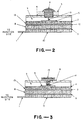
- Figs. 2, 3, 4 and 5 are schematic representations of some possible alternative activating mechanisms.
- Fig. 2 shows the piercing mechanism as described in the embodiment above.
- the plunger has a needle-like protrusion, 19, extending into the water chamber.
- the foil seal, 5, is held taut by the rigid support plate, 2. This plate also serves to strengthen the semipermeable membrane, 12, and prevent it being pushed into the water chamber by the osmotic pressure of the salt solution during operation of the pump. Depressing the plunger causes the needle, 19, to pierce the foil seal, allowing water to come into contact with the porous wick, 13.
- the pump then operates as described above.
- Fig. 1 shows the piercing mechanism as described in the embodiment above.
- the plunger has a needle-like protrusion, 19, extending into the water chamber.
- the foil seal, 5 is held taut by the rigid support plate, 2.
- This plate also serves to strengthen the semipermeable membrane, 12, and prevent it being pushed into the water
- FIG. 3 shows a scheme in which the seal, normally aluminum foil, separating the water chamber from the wick is connected to a rotatable dial, 15, at the top of the pump by means of epoxy adhesive, 14.
- the dial When the dial is turned, the foil is torn and the pumping action commences as described above.
- This mechanism may be preferable in some instances since a larger opening from the water chamber to the wick is produced, so response time may be less than that obtained with the puncture device. The possibility of the needle damaging the membrane is also eliminated.
- Fig. 4A shows a mechanism incorporating a rubber septum, 16, and a hollow needle, 20. Depressing the plunger causes the needle to pierce the septum and allows water to flow into contact with the wick, as shown in Fig.
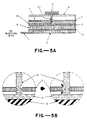
- FIG. 5A illustrates yet another possibility using a valve, 21.
- the valve is in the closed position, as shown in the left view of Fig. 5B.
- the dial is turned through 180 degrees, so that the valve is now in the fully open position, as shown in the right view of Fig. 5B. Water may then contact the porous wick as before.
- FIG. 6 A typical pumping profile for the basic embodiment of Fig. 1 is shown graphically in Fig. 6.
- the pumping rate depends on the membrane and salt chosen.
- the delivery rate of the pump depends on the membrane area, thickness and permeability.
- a suitable membrane material is essential to good performance of the pump.
- a preferred choice is a membrane made from one of the cellulose esters or ethers, such as cellulose acetate or cellulose butyrate.
- Cellulose acetate has a long record of use in membrane applications and can easily be formed into thin films of reproducable thickness with standard solution casting techniques, making it a particularly preferred choice.
- the osmotic pressure of the saturated salt solution should be large compared to the pressure required to pump the drug from the device, and the amount of salt used should be such that excess solid salt remains for the life of the pump. In this way a constant drug delivery rate can be sustained throughout the period of use. Furthermore, as can be seen from Fig. 6, the pump stops abruptly when the contents of the water chamber are exhausted. This gives the pump of the present invention a particular advantage, in that so long as the volume of the water chamber is less than that of the drug chamber, there is no risk of the high osmotic pressures involved causing the diaphragm to rupture, thereby pumping salt solution into the user.
- the osmotic pressure of the saturated salt solution depends on the molecular weight and solubility of the salt; for most common salts it is in the range 5,066 to 20,265 KN/m2 (50 to 200 atmospheres).
- a wide range of appropriate solutes is disclosed in U.S. Pat. No. 4,034,756, which is incorporated herein by reference.
- Preferred salts are sodium chloride, potassium chloride, magnesium sulfate and sodium sulfate. These give a good range of osmotic pressure differences across the membrane and provide a means whereby the flow rate of the pump can be varied to suit the desired application.
- Another advantage of the osmotic pump is that the high pressure under which the pump operates is large enough to overcome any back pressure that may build up as a result of a blockage in the delivery needle. These types of blockages are a not infrequent source of problems in other types of miniature infusion pumps.
- the infusion device can be filled, stored for extended periods of time and then activated on demand, it is essential that the expandable elastic diaphragm be completely impermeable to the chosen drug, otherwise slow migration of the fluids from the drug chamber into the salt chamber will cause the device to deteriorate during storage.
- a wide range of standard impermeable materials with good elastomeric properties is known in the art, such as latex rubber, polyisoprene, butyl rubber, nitrile rubber, copolymers of styrene/butadiene and the like. When storage periods of months or years are envisaged however, these materials may be less desireable.
- a preferred alternative is to use a standard elastomer faced with a thin layer of aluminum foil, which will rupture as soon as the elastic diaphragm begins to expand.
- a second preferred alternative is to use a metallized elastic material, formed by vacuum deposition of aluminum or other metals on an elastic rubber based material.
- the contents of the drug chamber may be an agent or combination of agents that would normally be administered by the parenterial route.
- a preferred embodiment employs a drug dissolved or suspended in an appropriate solvent, generally water.
- Drugs that could be used in this way include, but are not limited to, protein and polypeptide drugs such as insulin, growth hormones, interferon, interleukin2, leuteinizing hormone-releasing hormone (LHRH) and so on.
- any of the embodiments described above can incorporate the capability to delivery in initial priming dose for rapid initial therapy, followed by the prolonged period of slow controlled release.
- Various methods of accomplishing this end may be envisaged; a typical method is shown in Fig. 9, which serves to illustrate the principle.
- Fig. 9 the basic embodiment of Fig. 1 is extended to incorporate a priming dose mechanism, 18, which is built into an outer casing, 22, alongside the osmotic pump, 17, as shown in top view in Fig. 9A.
- the priming dose mechanism is in contact with a secondary drug chamber, 23. Operating the mechanism reduces the volume of the secondary drug chamber, and the corresponding volume of drug is delivered to the user.
- the priming dose mechanism may be operated by the screw principle, such that rotating the part protruding from the outer casing threads the mechanism further down into the casing and reduces the volume of the secondary drug chamber.
- it could be in the form of a spring-loaded plunger, a sliding valve, a piston and so on. This initial dose is followed by the slow controlled release delivery as the osmotic action of the pump begins.
- the present invention would extend the field of use of portable infusion devices considerably.
- areas of medicine to which the existing art cannot be applied could be addressed. These areas include, for instance, emergencies such as sever allergic reactions. Patients with a known history of allergy problems could keep the primed device on hand for use as necessary.
- Another desireable application is the administration of toxic antidotes.
- a DTIC report, "U.S. Army Chemical Effects Data Requirements", MONA-WE-1-82(1982) states that current antidotes to chemical warfare agents are unacceptable.
- MONA-WE-1-82(1982) states that current antidotes to chemical warfare agents are unacceptable.
- Several of the new antidotes under development must be delivered at a slow controlled rate over a period of one to three days.
- the present invention represents a novel solution to the problem of controlled release therapy under field conditions.
- the device could be filled months or years in advance and issued to service personnel prior to battle.
- Existing portable infusion pumps could not be used in this context. Long-term pain control therapy, treatment of infectious diseases, and other areas of medicine where portable infusion devices are currently employed, could also be addressed with this pump.
- the basic embodiment of the invention shown in Fig.1 was prepared.
- the body of the pump was machined from aluminum.
- the pump was 1.3 cm thick, 3.5 cm in diameter, and weighed 6.9 grams empty.
- the semipermeable membrane was cellulose acetate 50 microns thick, formed by casting a solution of cellulose acetate 398.10 (Eastman Kodak Co., Kingsport, Tennessee) dissolved in acetone onto a clean glass plate.
- the osmotic salt chosen was sodium chloride, the driving fluid water, and the elastic diaphragm was latex rubber faced with a thin disk of aluminum foil.
- the pumping profile obtained is shown graphically in Fig. 6. There was an initial high release of drug immediately after activation, after which the pump reached its steady state pumping rate of 1.0 ml per day for 27 hours. The pump stopped completely as soon as the water chamber was exhausted, although some drug solution remained in the drug chamber at that point.
- Embodiments were prepared as described in Example 1.
- the pumping rate was found to depend on membrane thickness as shown in Fig. 8.
- changing the membrane thickness is a method by which the pump can be tailored to deliver a specific drug dosage rate.
- Embodiments were prepared as described in Example 1, using a cellulose acetate membrane 15 ⁇ m thick. Four different osmotic salts were used; the driving fluid in each case was water. The results are summarized in Table 1,
- an appropriate salt may be chosen to fine tune the delivery rate of the pump.
- Example 2 An embodiment was prepared as described in Example 1, except that in this case the activating mechanism was a dial as shown in Fig. 3. When the dial was turned, the foil was torn and the pump activated. A larger opening from the water chamber to the wick was produced than with the puncture activator. As a result the time delay before pumping began was considerably reduced.
- the activating mechanism was a dial as shown in Fig. 3.
- Embodiments were prepared as described in Example 1.
- the drug chamber was filled with aqueous glycerin solutions of differing viscosities. The results are shown in Table 2
- the pumping rate was essentially independent of the viscosity of the drug solution.
Landscapes
- Health & Medical Sciences (AREA)
- Animal Behavior & Ethology (AREA)
- Veterinary Medicine (AREA)
- Anesthesiology (AREA)
- Biomedical Technology (AREA)
- Heart & Thoracic Surgery (AREA)
- Hematology (AREA)
- Engineering & Computer Science (AREA)
- General Health & Medical Sciences (AREA)
- Life Sciences & Earth Sciences (AREA)
- Public Health (AREA)
- Vascular Medicine (AREA)
- Infusion, Injection, And Reservoir Apparatuses (AREA)
- Media Introduction/Drainage Providing Device (AREA)
- Agricultural Chemicals And Associated Chemicals (AREA)
- Medicinal Preparation (AREA)
Priority Applications (1)
| Application Number | Priority Date | Filing Date | Title |
|---|---|---|---|
| AT87306903T ATE64103T1 (de) | 1986-08-04 | 1987-08-04 | Tragbare osmotische einrichtung zur infusion mit geregelter freigabe. |
Applications Claiming Priority (2)
| Application Number | Priority Date | Filing Date | Title |
|---|---|---|---|
| US06/892,991 US4838862A (en) | 1986-08-04 | 1986-08-04 | Portable controlled release osmotic infusion device |
| US892991 | 1986-08-04 |
Publications (2)
| Publication Number | Publication Date |
|---|---|
| EP0259013A1 EP0259013A1 (en) | 1988-03-09 |
| EP0259013B1 true EP0259013B1 (en) | 1991-06-05 |
Family
ID=25400846
Family Applications (1)
| Application Number | Title | Priority Date | Filing Date |
|---|---|---|---|
| EP87306903A Expired - Lifetime EP0259013B1 (en) | 1986-08-04 | 1987-08-04 | Portable controlled release osmotic infusion device |
Country Status (13)
| Country | Link |
|---|---|
| US (1) | US4838862A (da) |
| EP (1) | EP0259013B1 (da) |
| JP (1) | JP2529973B2 (da) |
| AT (1) | ATE64103T1 (da) |
| AU (1) | AU612980B2 (da) |
| CA (1) | CA1279543C (da) |
| DE (1) | DE3770550D1 (da) |
| DK (1) | DK169019B1 (da) |
| ES (1) | ES2022363B3 (da) |
| GR (1) | GR3002116T3 (da) |
| MX (1) | MX169737B (da) |
| NO (1) | NO166217C (da) |
| NZ (1) | NZ221270A (da) |
Cited By (2)
| Publication number | Priority date | Publication date | Assignee | Title |
|---|---|---|---|---|
| US6812205B2 (en) | 2000-03-15 | 2004-11-02 | The Brigham & Women's Hospital, Inc. | Suppression of vascular disorders by mucosal administration of heat shock protein peptides |
| US8691772B2 (en) | 2005-01-04 | 2014-04-08 | Yeda Research And Development Co. Ltd. | HSP60, HSP60 peptides and T cell vaccines for immunomodulation |
Families Citing this family (34)
| Publication number | Priority date | Publication date | Assignee | Title |
|---|---|---|---|---|
| US4898582A (en) * | 1988-08-09 | 1990-02-06 | Pharmetrix Corporation | Portable infusion device assembly |
| US4969884A (en) * | 1988-12-28 | 1990-11-13 | Alza Corporation | Osmotically driven syringe |
| US5019047A (en) * | 1989-06-16 | 1991-05-28 | Science Incorporated | Fluid delivery apparatus |
| US5030216A (en) * | 1989-12-15 | 1991-07-09 | Alza Corporation | Osmotically driven syringe |
| US5169390A (en) * | 1990-05-21 | 1992-12-08 | Athayde Amulya L | Osmotic infusion device |
| US5257987A (en) * | 1990-05-21 | 1993-11-02 | Pharmetrix Corporation | Controlled release osmotic infusion system |
| US5672167A (en) * | 1990-05-21 | 1997-09-30 | Recordati Corporation | Controlled release osmotic pump |
| US5158537A (en) * | 1990-10-29 | 1992-10-27 | Alza Corporation | Iontophoretic delivery device and method of hydrating same |
| US5156591A (en) * | 1990-12-13 | 1992-10-20 | S. I. Scientific Innovations Ltd. | Skin electrode construction and transdermal drug delivery device utilizing same |
| GB2250920B (en) * | 1990-12-18 | 1995-03-08 | Scras | Osmotic pumps |
| GB9027422D0 (en) * | 1990-12-18 | 1991-02-06 | Scras | Osmotically driven infusion device |
| US5310404A (en) * | 1992-06-01 | 1994-05-10 | Alza Corporation | Iontophoretic delivery device and method of hydrating same |
| ZA936662B (en) * | 1992-09-09 | 1994-06-17 | Alza Corp | Fluid driven dispensing device |
| US5540665A (en) * | 1994-01-31 | 1996-07-30 | Alza Corporation | Gas driven dispensing device and gas generating engine therefor |
| WO1998043611A1 (en) * | 1997-03-31 | 1998-10-08 | Alza Corporation | Diffusional implantable delivery system |
| US6994851B1 (en) | 1997-07-10 | 2006-02-07 | Mannkind Corporation | Method of inducing a CTL response |
| US6977074B2 (en) * | 1997-07-10 | 2005-12-20 | Mannkind Corporation | Method of inducing a CTL response |
| EP1140014B1 (en) * | 1998-12-31 | 2003-03-19 | Alza Corporation | Osmotic delivery system having space efficient piston |
| US6638727B1 (en) * | 1999-01-26 | 2003-10-28 | Cytyc Health Corporation | Methods for identifying treating or monitoring asymptomatic patients for risk reduction or therapeutic treatment of breast cancer |
| US6251432B1 (en) | 1999-07-01 | 2001-06-26 | Abbott Laboratories | Sustained release dosage form unit having latex coating and method of making the same |
| US6616652B1 (en) * | 2000-02-15 | 2003-09-09 | Microsolutions, Inc. | Osmotic pump delivery system with pre-hydrated membrane(s) and/or primable catheter |
| US6454759B2 (en) * | 2000-02-28 | 2002-09-24 | The Regents Of The University Of California | Microfabricated injectable drug delivery system |
| ATE443513T1 (de) * | 2001-09-17 | 2009-10-15 | Durect Corp | Vorrichtung und verfahren zur genauen abgabe eines wirkstoffs |
| DE10147554A1 (de) * | 2001-09-26 | 2003-04-10 | Ursula Luckow | Verfahren und Vorrichtung zur Formung und Handhabung von Werkstücken |
| FR2836520B1 (fr) * | 2002-02-28 | 2004-07-16 | Univ Joseph Fourier | Actionneur et moteur osmotiques |
| DE10233622A1 (de) | 2002-07-24 | 2004-02-12 | Disetronic Licensing Ag | Infusionspumpe, Verfahren, Steuerprogramm und Halbleiterbauelement zur dosierten Verabreichung einer medizinischen Flüssigkeit |
| US20060009739A1 (en) * | 2002-09-06 | 2006-01-12 | Durect Corporation | Implantable flow regulator with failsafe mode and reserve drug supply |
| EP1838338A2 (en) * | 2004-12-29 | 2007-10-03 | Mannkind Corporation | Methods to trigger, maintain and manipulate immune responses by targeted administration of biological response modifiers into lymphoid organs |
| WO2007013957A2 (en) * | 2005-07-22 | 2007-02-01 | University Of Utah Research Foundation | Osmotically driven dispense pump and related components for use in high pressure applications |
| US20090259301A1 (en) * | 2008-04-10 | 2009-10-15 | Daniel Gelbart | Detector for abnormal conditions inside body |
| JP2012501233A (ja) * | 2008-08-28 | 2012-01-19 | ミクロリン・エルエルシー | 有益薬剤を一定速度で送出するための装置および方法 |
| CN111991647B (zh) * | 2014-06-25 | 2022-06-10 | 魏民 | 用于给药的输液装置 |
| JP2021527508A (ja) * | 2018-06-18 | 2021-10-14 | サブクジェクト・エピエス | 注射デバイス用の浸透アクチュエータおよびそのような浸透アクチュエータを備える注射デバイス |
| US20240100250A1 (en) * | 2022-09-22 | 2024-03-28 | Carefusion 303, Inc. | Activatable medicament delivery containers and assemblies |
Family Cites Families (15)
| Publication number | Priority date | Publication date | Assignee | Title |
|---|---|---|---|---|
| US3604417A (en) * | 1970-03-31 | 1971-09-14 | Wayne Henry Linkenheimer | Osmotic fluid reservoir for osmotically activated long-term continuous injector device |
| US4034756A (en) * | 1971-01-13 | 1977-07-12 | Alza Corporation | Osmotically driven fluid dispenser |
| US3760984A (en) | 1971-09-29 | 1973-09-25 | Alza Corp | Osmotically powered agent dispensing device with filling means |
| US3845770A (en) | 1972-06-05 | 1974-11-05 | Alza Corp | Osmatic dispensing device for releasing beneficial agent |
| CH557178A (de) * | 1972-08-10 | 1974-12-31 | Siemens Ag | Geraet fuer die zufuehrung von medikamenten. |
| DE2626348C3 (de) * | 1976-06-11 | 1980-01-31 | Siemens Ag, 1000 Berlin Und 8000 Muenchen | Implantierbare Dosiereinrichtung |
| DE2721752C2 (de) * | 1977-05-13 | 1983-12-29 | Siemens AG, 1000 Berlin und 8000 München | In einen menschlichen oder tierischen Körper implantierbares Gerät zur Infusion einer medizinischen Flüssigkeit |
| US4188946A (en) * | 1977-10-07 | 1980-02-19 | Rayburn Robert L | Controllable partial rebreathing anesthesia circuit and respiratory assist device |
| US4193398A (en) * | 1978-05-25 | 1980-03-18 | Watson-Marlow Limited | Fluid displacement |
| US4410328A (en) * | 1981-07-10 | 1983-10-18 | Alza Corporation | Dispensing device with internal drive |
| EP0072057B1 (en) * | 1981-08-10 | 1988-02-10 | Duphar International Research B.V | Automatic injection syringe |
| US4474575A (en) * | 1982-02-01 | 1984-10-02 | Alza Corporation | Self-driven pump assembly and method of operation |
| DE3216109C2 (de) * | 1982-04-30 | 1985-07-18 | Drägerwerk AG, 2400 Lübeck | Kalibriergasgenerator |
| US4552561A (en) * | 1982-12-23 | 1985-11-12 | Alza Corporation | Body mounted pump housing and pump assembly employing the same |
| US4608048A (en) * | 1984-12-06 | 1986-08-26 | Alza Corporation | Dispensing device with drug delivery patterns |
-
1986
- 1986-08-04 US US06/892,991 patent/US4838862A/en not_active Expired - Lifetime
-
1987
- 1987-07-29 NO NO873185A patent/NO166217C/no unknown
- 1987-07-30 NZ NZ221270A patent/NZ221270A/xx unknown
- 1987-07-31 MX MX007545A patent/MX169737B/es unknown
- 1987-07-31 CA CA000543529A patent/CA1279543C/en not_active Expired - Fee Related
- 1987-08-03 AU AU76392/87A patent/AU612980B2/en not_active Ceased
- 1987-08-04 JP JP62195133A patent/JP2529973B2/ja not_active Expired - Lifetime
- 1987-08-04 AT AT87306903T patent/ATE64103T1/de not_active IP Right Cessation
- 1987-08-04 DK DK406687A patent/DK169019B1/da not_active IP Right Cessation
- 1987-08-04 ES ES87306903T patent/ES2022363B3/es not_active Expired - Lifetime
- 1987-08-04 EP EP87306903A patent/EP0259013B1/en not_active Expired - Lifetime
- 1987-08-04 DE DE8787306903T patent/DE3770550D1/de not_active Expired - Fee Related
-
1991
- 1991-06-12 GR GR91400811T patent/GR3002116T3/el unknown
Cited By (2)
| Publication number | Priority date | Publication date | Assignee | Title |
|---|---|---|---|---|
| US6812205B2 (en) | 2000-03-15 | 2004-11-02 | The Brigham & Women's Hospital, Inc. | Suppression of vascular disorders by mucosal administration of heat shock protein peptides |
| US8691772B2 (en) | 2005-01-04 | 2014-04-08 | Yeda Research And Development Co. Ltd. | HSP60, HSP60 peptides and T cell vaccines for immunomodulation |
Also Published As
| Publication number | Publication date |
|---|---|
| NO166217C (no) | 1991-06-19 |
| DK406687A (da) | 1988-02-05 |
| NO873185L (no) | 1988-02-05 |
| DK406687D0 (da) | 1987-08-04 |
| ES2022363B3 (es) | 1991-12-01 |
| NO166217B (no) | 1991-03-11 |
| DK169019B1 (da) | 1994-08-01 |
| NO873185D0 (no) | 1987-07-29 |
| JP2529973B2 (ja) | 1996-09-04 |
| US4838862A (en) | 1989-06-13 |
| GR3002116T3 (en) | 1992-12-30 |
| DE3770550D1 (de) | 1991-07-11 |
| AU7639287A (en) | 1988-02-11 |
| MX169737B (es) | 1993-07-21 |
| CA1279543C (en) | 1991-01-29 |
| JPS63260575A (ja) | 1988-10-27 |
| AU612980B2 (en) | 1991-07-25 |
| NZ221270A (en) | 1990-06-26 |
| EP0259013A1 (en) | 1988-03-09 |
| ATE64103T1 (de) | 1991-06-15 |
Similar Documents
| Publication | Publication Date | Title |
|---|---|---|
| EP0259013B1 (en) | Portable controlled release osmotic infusion device | |
| US4898582A (en) | Portable infusion device assembly | |
| US5030216A (en) | Osmotically driven syringe | |
| US5135498A (en) | Controlled release infusion device | |
| US5257987A (en) | Controlled release osmotic infusion system | |
| US5672167A (en) | Controlled release osmotic pump | |
| US5169390A (en) | Osmotic infusion device | |
| US5318540A (en) | Controlled release infusion device | |
| US4552561A (en) | Body mounted pump housing and pump assembly employing the same | |
| US5492534A (en) | Controlled release portable pump | |
| US5151093A (en) | Osmotically driven syringe with programmable agent delivery | |
| JP3058738B2 (ja) | 浸透ポンプ | |
| AU641633B2 (en) | Osmotically driven syringe | |
| US5785688A (en) | Fluid delivery apparatus and method | |
| US4619652A (en) | Dosage form for use in a body mounted pump | |
| US4539004A (en) | Self-driven pump assembly and method of operation | |
| GB2250920A (en) | Osmotic pumps | |
| IE912295A1 (en) | Osmotically driven syringe | |
| EP0731719A1 (en) | Controlled release infusion device | |
| PT98170A (pt) | Seringa accionada osmoticamente |
Legal Events
| Date | Code | Title | Description |
|---|---|---|---|
| PUAI | Public reference made under article 153(3) epc to a published international application that has entered the european phase |
Free format text: ORIGINAL CODE: 0009012 |
|
| AK | Designated contracting states |
Kind code of ref document: A1 Designated state(s): AT BE CH DE ES FR GB GR IT LI LU NL SE |
|
| 17P | Request for examination filed |
Effective date: 19880901 |
|
| 17Q | First examination report despatched |
Effective date: 19900220 |
|
| GRAA | (expected) grant |
Free format text: ORIGINAL CODE: 0009210 |
|
| AK | Designated contracting states |
Kind code of ref document: B1 Designated state(s): AT BE CH DE ES FR GB GR IT LI LU NL SE |
|
| REF | Corresponds to: |
Ref document number: 64103 Country of ref document: AT Date of ref document: 19910615 Kind code of ref document: T |
|
| ITF | It: translation for a ep patent filed | ||
| REF | Corresponds to: |
Ref document number: 3770550 Country of ref document: DE Date of ref document: 19910711 |
|
| ET | Fr: translation filed | ||
| PLBE | No opposition filed within time limit |
Free format text: ORIGINAL CODE: 0009261 |
|
| STAA | Information on the status of an ep patent application or granted ep patent |
Free format text: STATUS: NO OPPOSITION FILED WITHIN TIME LIMIT |
|
| 26N | No opposition filed | ||
| REG | Reference to a national code |
Ref country code: GR Ref legal event code: FG4A Free format text: 3002116 |
|
| EPTA | Lu: last paid annual fee | ||
| EAL | Se: european patent in force in sweden |
Ref document number: 87306903.3 |
|
| REG | Reference to a national code |
Ref country code: CH Ref legal event code: PFA Free format text: FLORA INC. |
|
| REG | Reference to a national code |
Ref country code: FR Ref legal event code: CD |
|
| REG | Reference to a national code |
Ref country code: ES Ref legal event code: PC2A Owner name: FLORA INC. |
|
| NLT1 | Nl: modifications of names registered in virtue of documents presented to the patent office pursuant to art. 16 a, paragraph 1 |
Owner name: FLORA INC. |
|
| PGFP | Annual fee paid to national office [announced via postgrant information from national office to epo] |
Ref country code: GB Payment date: 19970728 Year of fee payment: 11 |
|
| PGFP | Annual fee paid to national office [announced via postgrant information from national office to epo] |
Ref country code: FR Payment date: 19970811 Year of fee payment: 11 Ref country code: DE Payment date: 19970811 Year of fee payment: 11 |
|
| PGFP | Annual fee paid to national office [announced via postgrant information from national office to epo] |
Ref country code: AT Payment date: 19970813 Year of fee payment: 11 |
|
| PGFP | Annual fee paid to national office [announced via postgrant information from national office to epo] |
Ref country code: SE Payment date: 19970818 Year of fee payment: 11 |
|
| PGFP | Annual fee paid to national office [announced via postgrant information from national office to epo] |
Ref country code: ES Payment date: 19970819 Year of fee payment: 11 |
|
| PGFP | Annual fee paid to national office [announced via postgrant information from national office to epo] |
Ref country code: CH Payment date: 19970821 Year of fee payment: 11 |
|
| PGFP | Annual fee paid to national office [announced via postgrant information from national office to epo] |
Ref country code: GR Payment date: 19970822 Year of fee payment: 11 |
|
| PGFP | Annual fee paid to national office [announced via postgrant information from national office to epo] |
Ref country code: NL Payment date: 19970826 Year of fee payment: 11 |
|
| PGFP | Annual fee paid to national office [announced via postgrant information from national office to epo] |
Ref country code: BE Payment date: 19970925 Year of fee payment: 11 |
|
| PGFP | Annual fee paid to national office [announced via postgrant information from national office to epo] |
Ref country code: LU Payment date: 19971216 Year of fee payment: 11 |
|
| PG25 | Lapsed in a contracting state [announced via postgrant information from national office to epo] |
Ref country code: LU Free format text: LAPSE BECAUSE OF NON-PAYMENT OF DUE FEES Effective date: 19980804 Ref country code: GB Free format text: LAPSE BECAUSE OF NON-PAYMENT OF DUE FEES Effective date: 19980804 Ref country code: AT Free format text: LAPSE BECAUSE OF NON-PAYMENT OF DUE FEES Effective date: 19980804 |
|
| PG25 | Lapsed in a contracting state [announced via postgrant information from national office to epo] |
Ref country code: SE Free format text: LAPSE BECAUSE OF NON-PAYMENT OF DUE FEES Effective date: 19980805 Ref country code: ES Free format text: THE PATENT HAS BEEN ANNULLED BY A DECISION OF A NATIONAL AUTHORITY Effective date: 19980805 |
|
| PG25 | Lapsed in a contracting state [announced via postgrant information from national office to epo] |
Ref country code: LI Free format text: LAPSE BECAUSE OF NON-PAYMENT OF DUE FEES Effective date: 19980831 Ref country code: GR Free format text: LAPSE BECAUSE OF NON-PAYMENT OF DUE FEES Effective date: 19980831 Ref country code: CH Free format text: LAPSE BECAUSE OF NON-PAYMENT OF DUE FEES Effective date: 19980831 Ref country code: BE Free format text: LAPSE BECAUSE OF NON-PAYMENT OF DUE FEES Effective date: 19980831 |
|
| BERE | Be: lapsed |
Owner name: FLORA INC. Effective date: 19980831 |
|
| PG25 | Lapsed in a contracting state [announced via postgrant information from national office to epo] |
Ref country code: NL Free format text: LAPSE BECAUSE OF NON-PAYMENT OF DUE FEES Effective date: 19990301 |
|
| GBPC | Gb: european patent ceased through non-payment of renewal fee |
Effective date: 19980804 |
|
| REG | Reference to a national code |
Ref country code: CH Ref legal event code: PL |
|
| PG25 | Lapsed in a contracting state [announced via postgrant information from national office to epo] |
Ref country code: FR Free format text: LAPSE BECAUSE OF NON-PAYMENT OF DUE FEES Effective date: 19990430 |
|
| EUG | Se: european patent has lapsed |
Ref document number: 87306903.3 |
|
| NLV4 | Nl: lapsed or anulled due to non-payment of the annual fee |
Effective date: 19990301 |
|
| PG25 | Lapsed in a contracting state [announced via postgrant information from national office to epo] |
Ref country code: DE Free format text: LAPSE BECAUSE OF NON-PAYMENT OF DUE FEES Effective date: 19990601 |
|
| REG | Reference to a national code |
Ref country code: FR Ref legal event code: ST |
|
| REG | Reference to a national code |
Ref country code: ES Ref legal event code: FD2A Effective date: 20001204 |
|
| PG25 | Lapsed in a contracting state [announced via postgrant information from national office to epo] |
Ref country code: IT Free format text: LAPSE BECAUSE OF NON-PAYMENT OF DUE FEES Effective date: 20050804 |