EP0258718A2 - Sports shoe for running purposes - Google Patents
Sports shoe for running purposes Download PDFInfo
- Publication number
- EP0258718A2 EP0258718A2 EP19870111844 EP87111844A EP0258718A2 EP 0258718 A2 EP0258718 A2 EP 0258718A2 EP 19870111844 EP19870111844 EP 19870111844 EP 87111844 A EP87111844 A EP 87111844A EP 0258718 A2 EP0258718 A2 EP 0258718A2
- Authority
- EP
- European Patent Office
- Prior art keywords
- heel
- midsole
- sports shoe
- shoe according
- damping strip
- Prior art date
- Legal status (The legal status is an assumption and is not a legal conclusion. Google has not performed a legal analysis and makes no representation as to the accuracy of the status listed.)
- Withdrawn
Links
- 238000013016 damping Methods 0.000 claims description 39
- 210000002683 foot Anatomy 0.000 claims description 8
- 239000013013 elastic material Substances 0.000 claims description 2
- 230000002093 peripheral effect Effects 0.000 claims description 2
- 239000000654 additive Substances 0.000 claims 2
- 230000000996 additive effect Effects 0.000 claims 1
- 210000003789 metatarsus Anatomy 0.000 claims 1
- 206010016322 Feeling abnormal Diseases 0.000 abstract 1
- 230000009182 swimming Effects 0.000 description 4
- 239000000463 material Substances 0.000 description 2
- 241001663490 Dicologlossa cuneata Species 0.000 description 1
- 229920001875 Ebonite Polymers 0.000 description 1
- 230000015572 biosynthetic process Effects 0.000 description 1
- 230000000694 effects Effects 0.000 description 1
- 210000000548 hind-foot Anatomy 0.000 description 1
- 210000003127 knee Anatomy 0.000 description 1
- 210000000629 knee joint Anatomy 0.000 description 1
- 238000003801 milling Methods 0.000 description 1
- 239000004033 plastic Substances 0.000 description 1
- 230000001681 protective effect Effects 0.000 description 1
- 210000002303 tibia Anatomy 0.000 description 1
Images
Classifications
-
- A—HUMAN NECESSITIES
- A43—FOOTWEAR
- A43B—CHARACTERISTIC FEATURES OF FOOTWEAR; PARTS OF FOOTWEAR
- A43B5/00—Footwear for sporting purposes
- A43B5/06—Running shoes; Track shoes
-
- A—HUMAN NECESSITIES
- A43—FOOTWEAR
- A43B—CHARACTERISTIC FEATURES OF FOOTWEAR; PARTS OF FOOTWEAR
- A43B13/00—Soles; Sole-and-heel integral units
- A43B13/14—Soles; Sole-and-heel integral units characterised by the constructive form
Definitions
- the present invention relates to a sports shoe for running disciplines, in particular over longer distances, according to the preamble of claim 1.
- the damping element can consist of a U-shaped air cushion space or be designed as a soft-elastic damping element that is incorporated in the heel area. It can also be formed by a rigid rubber tube arranged in the rear heel area and extending transversely to the running direction.
- these known sports shoes can provide sufficient cushioning and reduce the feeling of swimming.
- Pronation is the twisting of the tibia around its longitudinal axis depending on the tilt of the foot inwards or outwards. This twist is small and always present, a pronation that is too large, i.e. a tipping of the foot over the flat tread position when treading, however, causes a change in the knee joint over a long period of time, which can be severely damaged in particular under longer loads of this type.
- the object of the present invention is accordingly to design a sports shoe of the type mentioned at the outset in such a way that, with sufficient cushioning and a reduced feeling of swimming, pronation is also counteracted to a harmful extent.
- the actual sole, in particular the midsole, in the milling area or the heel is not changed by the damping strip.
- These sole areas can therefore be provided with the desired damping and be trained accordingly to eliminate the feeling of swimming.
- the tilting ability of the foot can be individually adapted to the running style and the foot formation of the user. Accordingly, damping strips of different elasticity and degrees of hardness are provided, from which the runner can select the most suitable for him. This makes walking easier and prevents or at least reduces the risk of damage to the knee even under permanent stress.
- FIG. 1 denotes a rear section of a sports shoe for running disciplines, in particular for runs over longer distances.
- His paragraph 2 is either designed as an integrated sole part or it consists of separate sole parts, namely the actual outsole 3 and a cushioning midsole 3 ⁇ .
- the midsole 3 ⁇ is often designed as a wedge sole.
- the midsole 3 ⁇ is constructed in a manner known per se to be shock-absorbing, for example by using foamed, more or less flexible materials, into which additional damping elements with different damping characteristics can optionally be introduced.
- a shell is attached or integrated with these sole parts 3, 3 ⁇ , which forms the outer wall 4 of the paragraph 2. It is preferably provided on the back and optionally also on the side with an upwardly widened shell attachment 5 in the form of an outer heel cap.
- the outer wall 4 is preferably made of hard elastic material and has a thickness of 1.5 to 3 mm. It is provided with a circumferential groove 6, which extends from the area between the middle river and the hind foot, usually from the front end 7 of the paragraph 2 back to the heel end and on the opposite side in turn to the front end 7 of the paragraph 2. This groove 6 has a width of 2 to 10 mm, in particular 3 to 6 mm.
- the groove 6 is used for fixing a damping strip 8 which nestles around the outer wall 4 and is provided with a circumferential, inwardly projecting and fitting element 9 which fits into the groove 6.
- the groove 6 and the fixing element 9 can be coordinated with one another in such a way that they snap into one another, similar to the push-button principle.
- a fastening option for fastening to the heel 2 or to the midsole 3 ⁇ is provided at each end 10 of the damping strip 8.
- this fastening possibility consists, for example, of an opening 11 in each of the ends 10 of the damping strip 8 and in a correspondingly arranged continuous transverse bore 12 in the shoulder 2 or in the midsole 3 ⁇ .
- a continuous, rigid pin 13 with pin head 14 is inserted through the openings 11 and the transverse bore 12 as a fastening counterpart and braced on the opposite side by means of a cap screw 15 in paragraph 2 or in the midsole 3 ⁇ .
- the heel wall 4 has at least in the rear area 16 of the heel 2 a support surface 17 on which the lower edge of the damping strip 8 rests.
- the arrangement can advantageously also be chosen such that the damping strip 8 is completely or partially at least approximately flush with the outer wall 4 (see FIGS. 2 and 5). This can be achieved by appropriately deepening the outer wall 4 and / or by tapering the cross section of the damping strip towards its edge or towards its edges. At least in the rear peripheral portion 16 of paragraph 2, the outer surface 17 ⁇ of the bearing surface 17 is flush with the damping strip 8.
- the damping strip 8 For a better hold of the damping strip 8 when it occurs with the heel, it has a widening 18 in the rear circumferential section 16, so that it extends towards the shell extension 5.
- the outer wall of the shell extension 5 runs steeply obliquely inwards, so that there is an additional upper stop surface 19 for the damping strip 8 or for its widening 18.
- fixing element sections 20 in the form of inwardly projecting webs, warts or the like can also be provided, as shown in FIG. 3, which engage or snap into the groove 6.
- the recesses 20 corresponding recesses in paragraph 2 or in the outer wall 4 can be provided.
- the damping strip 8 can be attached to the heel 2 or to the outer wall 4 or in the midsole 3 ⁇ by attaching an inwardly projecting locking member in the form of a push button 21 to the ends 10, for example, is molded on, which can be buttoned into an opening 22 in the outer wall 4 with a free space 23 behind it in the midsole 3 ⁇ .
- the effect of the damping strip 8 is based on the fact that the edges of the paragraph 2 are stiffer than the remaining surface area of the paragraph 2 or the midsole 3 ⁇ . As a result, the shoe is brought into its position lying flat on the ground comparatively quickly when it occurs. However, this arrangement prevents the shoe and thus the foot from tipping over the flat position, which leads to the harmful pronation or overpronation.
- a suitable damping strip can be selected, which adjusts the pronation harmless measure limited. Damping strips of different elasticity and / or degrees of hardness and / or geometric design are available for this.
- the damping strip 8 with the heel outer wall 4 is at least approximately flush with corresponding depressions in the heel 2 or in the midsole 3 ⁇ and / or by tapering its cross section to its edge 24 or to its edges 24, 24.
- This embodiment is shown in a reduced representation in FIG. 5.
- the heel 2 or the midsole 3 ⁇ is stabilized twice, namely on the one hand by the outer wall 4, the material of which preferably consists of a hard plastic or hard rubber with a degree of hardness of more than 60 Shore A. and, on the other hand, through the damping strip 8 described in detail above.
- the ends of the outer wall 4 on the shoulder side act as comparatively rigid supports for the fastening and / or latching means 15, 21.
Landscapes
- Health & Medical Sciences (AREA)
- General Health & Medical Sciences (AREA)
- Physical Education & Sports Medicine (AREA)
- Footwear And Its Accessory, Manufacturing Method And Apparatuses (AREA)
Abstract
Description
Die vorliegende Erfindung bezieht sich auf einen Sportschuh für Laufdisziplinen, insbesondere über längere Distanzen, gemäß dem Oberbegriff des Anspruches 1.The present invention relates to a sports shoe for running disciplines, in particular over longer distances, according to the preamble of
Ein derartiger Sportschuh ist aus der DE-OS 24 60 034 bekannt. Dort kann das Dämpfungsglied aus einem U-förmigen Luftkissenraum bestehen oder als weichelastisches Dämpfungsglied ausgebildet sein, das im Absatzbereich eingearbeitet ist. Es kann auch durch ein im hinteren Absatzbereich fest angeordnetes, quer zur Laufrichtung verlaufendes Rohr aus steifem Gummi gebildet sein.Such a sports shoe is known from DE-OS 24 60 034. There, the damping element can consist of a U-shaped air cushion space or be designed as a soft-elastic damping element that is incorporated in the heel area. It can also be formed by a rigid rubber tube arranged in the rear heel area and extending transversely to the running direction.
Aus der US-PS 37 85 646 ist ein Schuh bekannt, dessen gesamte Sohle dadurch eine besondere Dämpfungscharakteristik besitzt, daß die Sohle über ihre ganze Länge mit jeweils von einer zu anderen Seite durchgehenden Querbohrungen versehen ist.From US-PS 37 85 646 a shoe is known, the entire sole of which has a special damping characteristic in that the sole is provided over its entire length with transverse bores passing from one side to the other.
Weiterhin ist aus der DE-PS 29 04 540 bekannt. Querbohrungen im Absatz im Bereich der Aufstandsfläche vorzusehen, in die federelastisch zusammendrückbare und biegbare Stützkörper von der Seite her auswechselbar eingesetzt werden können. Diese Anordnung dient dazu, eine hohe Dämpfungsfähigkeit zu erreichen, die den Kontakt zu der Laufbahn sichern und bei ausreichender Weichheit trotzdem des bekannte Schwimmgefühl verhindern soll.Furthermore, it is known from DE-PS 29 04 540. Provide cross holes in the heel in the area of the footprint, in the resiliently compressible and bendable support body can be used interchangeably from the side. This arrangement serves to achieve a high damping capacity, which should ensure contact with the running track and should nevertheless prevent the known feeling of swimming with sufficient softness.
Diese bekannten Sportschuhe können zwar je nach Auslegung der Sohle und der Stützen eine genügende Dämpfung erbringen und das Schwimmgefühl reduzieren.Depending on the design of the sole and the supports, these known sports shoes can provide sufficient cushioning and reduce the feeling of swimming.
Ein wesentliches Merkmal eines Sportschuhes für Laufdisziplinen, insbesondere über längere Distanzen, ist es jedoch, auch der Pronation im schädlichen Umfange entgegenzuwirken. Unter Pronation versteht man die Verdrehung des Schienbeins um seine Längsachse in Abhängigkeit von der Kipplage des Fußes nach innen oder außen. Diese Verdrehung ist zwar gering und immer vorhanden, eine zu große Pronation, d.h. ein Kippen des Fußes über die flache Auftrittslage beim Auftreten hinweg, bewirkt jedoch über längere Zeit eine Veränderung des Kniegelenks, das insbesondere bei längeren Belastungen dieser Art unter Umständen schwer geschädigt werden kann.An essential feature of a sports shoe for running disciplines, especially over longer distances, is to counteract pronation to a harmful extent. Pronation is the twisting of the tibia around its longitudinal axis depending on the tilt of the foot inwards or outwards. This twist is small and always present, a pronation that is too large, i.e. a tipping of the foot over the flat tread position when treading, however, causes a change in the knee joint over a long period of time, which can be severely damaged in particular under longer loads of this type.
Aufgabe der vorliegenden Erfindung ist es demgemäß, einen Sportschuh der eingangs erwähnten Art derart auszubilden, daß bei ausreichender Dämpfung und reduziertem Schwimmgefühl auch der Pronation im schädlichen Umfange entgegengewirkt wird.The object of the present invention is accordingly to design a sports shoe of the type mentioned at the outset in such a way that, with sufficient cushioning and a reduced feeling of swimming, pronation is also counteracted to a harmful extent.
Gelöst wird diese Aufgabe durch die im Kennzeichen des Anspruches 1 angegebenen Merkmale.This object is achieved by the features specified in the characterizing part of
Durch den Dämpfungsstreifen wird die eigentliche Sohle, insbesondere die Zwischensohle, im Frsenbereich bzw. wird auch der Absatz nicht verändert. Diese Sohlenbereiche können also mit der gewünschten Dämpfung versehen und zur Beseitigung des Schwimmgefühls entsprechend ausgebildet werden. Durch geeignete Wahl des Dämpfungsstreifens kann aber die Kippfähigkeit des Fußes individuell an den Laufstil und die Fußbildung des Benutzers angepaßt werden. Demzufolge sind Dämpfungsstreifen unterschiedlicher Elastizität und Härtegrade vorgesehen, aus denen der Läufer die für ihn geeignetsten auswählen kann. Dadurch wird das Laufen erleichtert und die Gefahr der Schädigung des Knies auch bei Dauerbelastungen verhindert oder zumindest verringert.The actual sole, in particular the midsole, in the milling area or the heel is not changed by the damping strip. These sole areas can therefore be provided with the desired damping and be trained accordingly to eliminate the feeling of swimming. By a suitable choice of the damping strip, the tilting ability of the foot can be individually adapted to the running style and the foot formation of the user. Accordingly, damping strips of different elasticity and degrees of hardness are provided, from which the runner can select the most suitable for him. This makes walking easier and prevents or at least reduces the risk of damage to the knee even under permanent stress.
Weitere vorteilhafte Einzelheiten der Erfindung sind in den Unteransprüchen angegeben und werden nachfolgend anhand der in der Zeichnung veranschaulichten Ausführungsbeispiele näher beschrieben.Further advantageous details of the invention are specified in the subclaims and are described in more detail below with reference to the exemplary embodiments illustrated in the drawing.
Dabei zeigen:
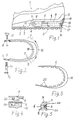
- Fig. 1 eine Teilansicht der hinteren Hälfte eines Sportschuhes mit der eigentlichen Laufsohle und der dämpfenden Zwischensohle,
- Fig. 2
und 3 je eine Ausführungsmöglichkeit eines Dämpfungsstreifens, - Fig. 4 eine weitere Befestigungsmöglichkeit des Dämpfungsstreifens und
- Fig. 5 den Querschnitt des Absatzendes mit zur Laufsohle bündig abschließenden Dämpfungsstreifen.
- 1 is a partial view of the rear half of a sports shoe with the actual outsole and the cushioning midsole,
- Fig. 2
and 3 each a possible implementation of a damping strip, - Fig. 4 shows another way of fastening the damping strip and
- Fig. 5 shows the cross section of the heel end with damping strips which are flush with the outsole.
Mit 1 ist ein hinterer Abschnitt eines Sportschuhes für Laufdisziplinen, insbesondere für Läufe über längere Distanzen, bezeichnet. Sein Absatz 2 ist entweder als integriertes Sohlenteil ausgebildet oder er besteht aus separaten Sohlenteilen, nämlich aus der eigentlichen Laufsohle 3 und aus einer dämpfenden Zwischensohle 3ʹ. Die Zwischensohle 3ʹ ist häufig als Keilsohle ausgebildet.1 denotes a rear section of a sports shoe for running disciplines, in particular for runs over longer distances. His
Die Zwischensohle 3ʹ ist in an sich bekannter Weise stoßdämpfend aufgebaut, beispielsweise durch Verwendung geschäumter, mehr oder weniger weichelastischer Materialien, in die gegebenenfalls zusätzliche Dämpfungselemente mit anderer Dämpfungscharakteristik eingebracht sein können.The midsole 3ʹ is constructed in a manner known per se to be shock-absorbing, for example by using foamed, more or less flexible materials, into which additional damping elements with different damping characteristics can optionally be introduced.
An der Laufsohle 3 bzw. an der Zwischensohle 3ʹ ist eine Schale angebracht oder mit diesen Sohlenteilen 3, 3ʹ integriert, die die Außenwand 4 des Absatzes 2 bildet. Sie ist vorzugsweise rückseitig und gegebenenfalls auch seitlich mit einem nach oben erweiterten Schalenansatz 5 in Form einer äußeren Fersenkappe versehen. Die Außenwand 4 besteht vorzugsweise aus hartelastischem Material und besitzt eine Dicke von 1,5 bis 3 mm. Sie ist mit einer umlaufenden Rille 6 versehen, die sich vom Bereich zwischen Mittelfluß und Hinterfuß, in der Regel vom vorderen Ende 7 des Absatzes 2 aus nach hinten zum Fersenende und auf der gegenüberliegenden Seite wiederum bis zum vorderen Ende 7 des Absatzes 2 erstreckt. Diese Rille 6 besitzt eine Breite von 2 bis 10 mm, insbesondere von 3 bis 6 mm.On the
Die Rille 6 dient fur Fixierung eines Dämpfungsstreifens 8, der sich um die Außenwand 4 schmiegt und mit einem umlaufenden, nach innen ragenden und in die Rille 6 passenden Fixierelement 9 versehen ist. Die Rille 6 und das Fixierelement 9 können so aufeinander abgestimmt sein, daß sie, ähnlich dem Druckknopfprinzip, ineinanderrasten. Vorzugsweise zusätzlich oder aber auch ausschließlich ist an jedem Ende 10 des Dämpfungsstreifens 8 eine Befestigungsmöglichkeit zur Befestigung am Absatz 2 bzw. an der Zwischensohle 3ʹ vorgesehen. Gemäß den Figuren 1 und 2 besteht diese Befestigungsmöglichkeit beispielsweise aus je einer Öffnung 11 in den Enden 10 des Dämpfungsstreifens 8 sowie in einer entsprechend angeordneten durchgehenden Querbohrung 12 im Absatz 2 bzw. in der Zwischensohle 3ʹ.The
Durch die Öffnungen 11 und die Querbohrung 12 wird als Befestigungsgegenstück ein durchgehender, starrer Stift 13 mit Stiftkopf 14 gesteckt und auf der gegenüberliegenden Seite mittels einer Kopfschraube 15 im Absatz 2 bzw. in der Zwischensohle 3ʹ verspannt.A continuous,
Günstigerweise besitzt die Absatzwand 4 zumindest im hinteren Bereich 16 des Absatzes 2 eine Auflagefläche 17, auf der der untere Rand des Dämpfungsstreifens 8 aufliegt. Im übrigen kann die Anordnung vorteilhafterweise auch so gewählt werden, daß der Dämpfungsstreifen 8 ganz oder abschnittsweise zumindest annähernd bündig mit der Außenwand 4 abschließt (vgl. Fig. 2 und 5). Dies kann durch entsprechende Vertiefung der Außenwand 4 oder/und durch Verjüngen des Querschnitts des Dämpfungsstreifens zu seinem Rand oder zu seinen Rändern hin erreicht werden. Zumindest im hinteren Umfangsabschnitt 16 des Absatzes 2 schließt die Außenfläche 17ʹ der Auflagefläche 17 mit dem Dämpfungsstreifen 8 bündig ab.Advantageously, the
Zum besseren Halt des Dämpfungsstreifens 8 beim Auftreten mit der Ferse besitzt er im hinteren Umfangsabschnitt 16 eine Verbreiterung 18, so daß er sich zu dem Schalenansatz 5 hin erstreckt. Die Außenwand des Schalenansatzes 5 verläuft steil schräg nach innen, so daß sich eine zusätzliche obere Anschlagfläche 19 für den Dämpfungsstreifen 8 bzw. für dessen Verbreiterung 18 ergibt.For a better hold of the
Anstelle eines durchgehenden Fixierelements 9 können auch, wie in Fig. 3 gezeigt, Fixierelementabschnitte 20 in Form von nach innen ragenden Stegen, Warzen oder dgl. vorgesehen sein, die in die Rille 6 eingreifen oder einrasten. Entsprechend können in diesem Fall anstelle einer durchgehenden Rille 6 den Fixierabschnitten 20 entsprechende Aussparungen im Absatz 2 bzw. in der Außenwand 4 vorgesehen sein.Instead of a
Weiterhin kann, wie in Fig. 4 gezeigt, die Befestigung des Dämpfungsstreifens 8 am Absatz 2 bzw. an der Außenwand 4 beziehungsweise in der Zwischensohle 3ʹ dadurch erfolgen, daß an den Enden 10 je ein nach innen ragendes Rastglied in Form eines Druckknopfes 21 angebracht, beispielsweise angeformt ist, das in eine Öffnung 22 in der Außenwand 4 mit dahinter liegendem Freiraum 23 in der Zwischensohle 3ʹ einknöpfbar ist.Furthermore, as shown in FIG. 4, the
Die Wirkung des Dämpfungsstreifens 8 beruht darauf, daß die Ränder des Absatzes 2 steifer sind als der übrige Flächenbereich des Absatzes 2 bzw. der Zwischensohle 3ʹ. Dadurch wird der Schuh beim Auftreten vergleichsweise schnell in seine flach auf dem Untergrund aufliegende Lage gebracht. Es wird jedoch durch diese Anordnung verhindert, daß der Schuh und damit der Fuß noch weiter über die flache Lage kippt, was zu der schädlichen Pronation bzw. Überpronation führt. Um je nach natürlicher Fußstellung des Läufers und/oder je nach dessen Laufstil, bei dem der Fuß entweder auf der Längs-Mittelinie des Körpers aufgesetzt wird oder weiter außen oder auch weiter innen, kann jeweils ein geeigneter Dämpfungsstreifen ausgewählt werden, der die Pronation auf ein unschädliches Maß begrenzt. Hierfür stehen Dämpfungsstreifen unterschiedlicher Elastizität und/oder Härtegrade und/oder geometrischer Ausbildung zur Verfügung.The effect of the
Auch wenn im Ausführungsbeispiel gemäß Fig. 1 ein Absatz 2 mit einer umlaufenden, vergleichsweise harten Außenwand dargestellt und beschrieben ist, ist die erfindungsgemäße Dämpfungsanordnung grundsätzlich auch bei Absätzen 2 bzw. Zwischensohlen 3ʹ ohne eine entsprechende, schützende Außenwand 4 einsetzbar.1, a
Schließlich ist es nach einer Variante der vorliegenden Erfindung auch möglich, daß der Dämpfungsstreifen 8 mit der Absatzaußenwand 4 durch entsprechende Vertiefungen im Absatz 2 oder in der Zwischensohle 3ʹ und/oder durch Verjüngung seines Querschnittes zu seinem Rand 24 bzw. zu seinen Rändern 24, 24 wenigstens annähernd bündig abschließt. Diese Ausführungsform ist in verkleinerter Darstellung in Fig. 5 wiedergegeben.Finally, it is also possible according to a variant of the present invention that the
Im Falle der Verwendung einer Außenwand 4 gemäß der Ausführung nach Figur 1 ist der Absatz 2 bzw. die Zwischensohle 3ʹ zweifach stabilisiert, nämlich einerseits durch die Außenwand 4, deren Material bevorzugt aus einem Hartkunststoff oder Hartgummi mit einem Härtegrad von mehr als 60 Shore A besteht und andererseits durch den vorstehend ausführlich beschriebenen Dämpfungsstreifen 8. Bei dieser Ausführungsform erhält man also eine besonders hohe Sicherheit für die Vermeidung der Pronation im schädlichen Umfange. Gleichzeitig wirken die absatzseitigen Enden der Außenwand 4 als vergleichsweise starre Auflager für die Befestigungs und/oder Rastmittel 15, 21.If an
Claims (12)
Applications Claiming Priority (2)
| Application Number | Priority Date | Filing Date | Title |
|---|---|---|---|
| DE3629340 | 1986-08-28 | ||
| DE19863629340 DE3629340A1 (en) | 1986-08-28 | 1986-08-28 | SPORTSHOE FOR RUNNING DISCIPLINES |
Publications (1)
| Publication Number | Publication Date |
|---|---|
| EP0258718A2 true EP0258718A2 (en) | 1988-03-09 |
Family
ID=6308423
Family Applications (1)
| Application Number | Title | Priority Date | Filing Date |
|---|---|---|---|
| EP19870111844 Withdrawn EP0258718A2 (en) | 1986-08-28 | 1987-08-15 | Sports shoe for running purposes |
Country Status (2)
| Country | Link |
|---|---|
| EP (1) | EP0258718A2 (en) |
| DE (1) | DE3629340A1 (en) |
Cited By (2)
| Publication number | Priority date | Publication date | Assignee | Title |
|---|---|---|---|---|
| EP1733636A1 (en) | 2005-06-16 | 2006-12-20 | Diadora - Invicta S.P.A. | Footwear with adjustable stabilising system, particularly to control pronation and/or supination |
| CN110799055A (en) * | 2017-05-08 | 2020-02-14 | 耐克创新有限合伙公司 | Modular article of footwear and method of making a customized article of footwear |
Families Citing this family (3)
| Publication number | Priority date | Publication date | Assignee | Title |
|---|---|---|---|---|
| DE3734205A1 (en) * | 1987-10-09 | 1989-04-27 | Dassler Puma Sportschuh | SHOES, ESPECIALLY SPORTSHOES, OR SHOES FOR MEDICAL PURPOSES |
| CA2047433A1 (en) * | 1991-07-19 | 1993-01-20 | James Russel | Power suspension system concept |
| CN110731572A (en) * | 2019-10-30 | 2020-01-31 | 哈尔滨体育学院 | Detachable nail-protecting sole of long jump nailed shoe |
-
1986
- 1986-08-28 DE DE19863629340 patent/DE3629340A1/en not_active Withdrawn
-
1987
- 1987-08-15 EP EP19870111844 patent/EP0258718A2/en not_active Withdrawn
Cited By (4)
| Publication number | Priority date | Publication date | Assignee | Title |
|---|---|---|---|---|
| EP1733636A1 (en) | 2005-06-16 | 2006-12-20 | Diadora - Invicta S.P.A. | Footwear with adjustable stabilising system, particularly to control pronation and/or supination |
| CN110799055A (en) * | 2017-05-08 | 2020-02-14 | 耐克创新有限合伙公司 | Modular article of footwear and method of making a customized article of footwear |
| US11723435B2 (en) | 2017-05-08 | 2023-08-15 | Nike, Inc. | Modular article of footwear and method of manufacturing customized article of footwear |
| CN110799055B (en) * | 2017-05-08 | 2023-10-31 | 耐克创新有限合伙公司 | Modular items of footwear and methods of manufacturing customized items of footwear |
Also Published As
| Publication number | Publication date |
|---|---|
| DE3629340A1 (en) | 1988-03-03 |
Similar Documents
| Publication | Publication Date | Title |
|---|---|---|
| DE2908019C3 (en) | Foot-supporting sole | |
| EP0373336B1 (en) | Insert for a shoe | |
| EP0146846B1 (en) | Shoe outsole, in particular for a sports shoe, with adjustable heel cushioning | |
| EP0207063B1 (en) | Golf shoe | |
| DE19950121C1 (en) | Sports shoe sole has lateral and medial damping elements attached to carrier plate via L-shaped spring elements | |
| EP0185781B1 (en) | Shoe sole of plastic material or rubber | |
| EP2540181B1 (en) | Sole for a shoe, in particular a running shoe | |
| DE3318121A1 (en) | SHOE SOLE | |
| DE3734205A1 (en) | SHOES, ESPECIALLY SPORTSHOES, OR SHOES FOR MEDICAL PURPOSES | |
| DE3716424A1 (en) | OUTSOLE FOR SPORTSHOES | |
| EP2111771A1 (en) | Shoe for rolling walk | |
| DE8022761U1 (en) | Sports shoes, in particular jogging shoes | |
| EP3151694A1 (en) | Shoe, in particular a running shoe | |
| DE3043425A1 (en) | Shoe for roller or ice skate - has rigid, plastics inner sole and sealed elastic upper with couplings | |
| DE2751146A1 (en) | Sports shoe for use on hard ground - includes sole with flexible part under foot arch, and harder heel and ball part | |
| EP0258718A2 (en) | Sports shoe for running purposes | |
| DE29919124U1 (en) | Outsole for shoes, especially for safety shoes | |
| DE69418431T2 (en) | Exercise shoe sole | |
| DE3106729A1 (en) | Interchangeable insole for sports shoes and leisure shoes | |
| DE8216935U1 (en) | Sports shoe | |
| WO2011020798A1 (en) | Tread cushion for shoe soles | |
| DE8623132U1 (en) | Sports shoe for running disciplines | |
| DE102006058591A1 (en) | Shoe sole or footwear with shoe sole | |
| DE102013104275A1 (en) | Modular shoe | |
| DE102009022910B3 (en) | Base for e.g. shoe, has hard plastic layer and soft plastic layer separated from each other, contact surface lies under composite, and reinforcement-and spring plate interrupted on line in defined width |
Legal Events
| Date | Code | Title | Description |
|---|---|---|---|
| PUAI | Public reference made under article 153(3) epc to a published international application that has entered the european phase |
Free format text: ORIGINAL CODE: 0009012 |
|
| AK | Designated contracting states |
Kind code of ref document: A2 Designated state(s): AT CH DE FR GB IT LI |
|
| STAA | Information on the status of an ep patent application or granted ep patent |
Free format text: STATUS: THE APPLICATION IS DEEMED TO BE WITHDRAWN |
|
| 18D | Application deemed to be withdrawn |
Effective date: 19900301 |
|
| RIN1 | Information on inventor provided before grant (corrected) |
Inventor name: BAUER, WILLI |