EP0258652B1 - Zentrifugenrotor mit Überlaufrinne - Google Patents
Zentrifugenrotor mit Überlaufrinne Download PDFInfo
- Publication number
- EP0258652B1 EP0258652B1 EP87111160A EP87111160A EP0258652B1 EP 0258652 B1 EP0258652 B1 EP 0258652B1 EP 87111160 A EP87111160 A EP 87111160A EP 87111160 A EP87111160 A EP 87111160A EP 0258652 B1 EP0258652 B1 EP 0258652B1
- Authority
- EP
- European Patent Office
- Prior art keywords
- rotor
- groove
- liquid
- centrifuge rotor
- cavity
- Prior art date
- Legal status (The legal status is an assumption and is not a legal conclusion. Google has not performed a legal analysis and makes no representation as to the accuracy of the status listed.)
- Expired - Lifetime
Links
- 239000007788 liquid Substances 0.000 claims abstract description 55
- 239000012530 fluid Substances 0.000 claims 2
- 230000003068 static effect Effects 0.000 claims 1
- 238000011109 contamination Methods 0.000 description 6
- 238000007789 sealing Methods 0.000 description 5
- 230000002939 deleterious effect Effects 0.000 description 2
- 230000000694 effects Effects 0.000 description 2
- 231100001261 hazardous Toxicity 0.000 description 2
- 230000002093 peripheral effect Effects 0.000 description 2
- RTAQQCXQSZGOHL-UHFFFAOYSA-N Titanium Chemical compound [Ti] RTAQQCXQSZGOHL-UHFFFAOYSA-N 0.000 description 1
- 238000005119 centrifugation Methods 0.000 description 1
- 239000013056 hazardous product Substances 0.000 description 1
- 238000003754 machining Methods 0.000 description 1
- 239000000463 material Substances 0.000 description 1
- 229910052719 titanium Inorganic materials 0.000 description 1
- 239000010936 titanium Substances 0.000 description 1
Images

Classifications
-
- B—PERFORMING OPERATIONS; TRANSPORTING
- B04—CENTRIFUGAL APPARATUS OR MACHINES FOR CARRYING-OUT PHYSICAL OR CHEMICAL PROCESSES
- B04B—CENTRIFUGES
- B04B5/00—Other centrifuges
- B04B5/04—Radial chamber apparatus for separating predominantly liquid mixtures, e.g. butyrometers
- B04B5/0407—Radial chamber apparatus for separating predominantly liquid mixtures, e.g. butyrometers for liquids contained in receptacles
- B04B5/0414—Radial chamber apparatus for separating predominantly liquid mixtures, e.g. butyrometers for liquids contained in receptacles comprising test tubes
-
- B—PERFORMING OPERATIONS; TRANSPORTING
- B04—CENTRIFUGAL APPARATUS OR MACHINES FOR CARRYING-OUT PHYSICAL OR CHEMICAL PROCESSES
- B04B—CENTRIFUGES
- B04B7/00—Elements of centrifuges
- B04B7/02—Casings; Lids
- B04B2007/025—Lids for laboratory centrifuge rotors
Definitions
- the present invention relates to a centrifuge rotor and, in particular, to a centrifuge rotor having a liquid containment arrangement adapted to contain any liquid spilled within the rotor and to prevent contamination of the centrifuge by that spilled liquid.
- a centrifuge rotor is a device adapted to expose a sample carried in a suitable sample container to a predetermined centrifugal force field. This field is achieved by causing the rotor to rotate at a selected angular velocity, typically in the range from ten thousand to approximately eighty thousand revolutions per minute.
- the rotor is provided with an annular array of sample receiving cavities which are disposed concentrically about the axis of rotation of the rotor. If the longitudinal axis of each of the cavities is inclined toward the rotational axis of the rotor, the device is known as a fixed angle rotor.
- the samples under test are each contained in a container which, in the typical application, is closed by a suitable capping arrangement.
- the capping arrangement is necessary in the event that the sample is a biologically hazardous material to insure that the sample is appropriately isolated from the environment.
- the capping arrangement When the sample is not hazardous the capping arrangement may be omitted so long as the operator fills the tube only to a predetermined level. It should be noted that since the tubes are received in the inclined cavities in the rotor the predetermined level to which the tube is filled lies some distance below the rim of the tube. Care must be exercised to insure that the tube is filled only to this level to guard against the possibility that centrifugal force effects will cause the contents of the tube to overflow and spill from the inclined tube when the tube is inserted into the rotor and rotated to its operational speed.
- the containers are themselves susceptible to rupture. Thus, even if a capping arrangement has been used, and even if the operator has exercised care to introduce only the proper volume of liquid into the container, there still may occur instances in which the liquid contents of the tube will spill into the rotor.
- a cover may be provided over the rotor.
- the cover has a depending skirt which seats against an upstanding rim of the rotor. When secured in place the skirt and the rim cooperate to confine the liquid within the rotor.
- Exemplary of such a structure is the device shown in US-A 3,819,111 assigned to the assignee of the present 4,202,487 and 4,360,151 describe other rotor covers for use in a centrifuge instrument.
- a cover may itself become dislodged from the rotor due to the centrifugally induced force of the spilled liquid acting against the underside of the cover.
- Structural arrangements which eliminate this occurrence by isolating the cover from the spill are known in the art.
- United States Patent 4,372,483 discloses a centrifuge rotor having an annular liquid containment lip machined into the body of the rotor above the tube cavities. The lip serves to confine any liquid present due to container rupture, cap leakage or inadvertent excessive filling.
- the annular lip extends radially inwardly to overlie a portion of the cavities to confine any liquid liberated into the body of the rotor. The lip prevents the liquid from contacting and exerting pressure on the cover of the rotor.
- DE-A-2 448 199 discloses a centrifuge rotor comprising a rotor body having several cavities for housing sample containers. The cavity is covered by a cover fixed to the rotor body. In the lower surface of the cover or in the upper surface of the rotor body there is provided a groove containing a sealing ring that is pressed against the upper surface of the rotor body.
- the sealing ring acts as a relief valve that opens in case of a remarkable overpressure within the cavity. Such overpressure occurs due to leakage of a sample container.
- the liquid relieved from the sample container is pressed by the centrifugal force against the sealing ring and said liquid temporarily deforms the sealing ring such that the liquid passes the sealing ring and said liquid is spilled radially from the gap between the rotor body and the cover. In this way, a substantial overpressure within the cavity is avoided. However, when the rotor body is slowed down to stop the rotation, any liquid still contained within the cavity of the rotor body rinses down and may contaminate the interior of the rotor body.
- the rotor body has a groove formed therein.
- the groove is arranged to surround the radially outer periphery of the tube cavities such that as the rotor slows any spilled liquid drains into and is contained within the groove. As a consequence the spilled liquid is prevented from entering into the cavity in the body of the rotor.
- the groove is continuously circumferentially disposed about the rotor body.
- the groove is defined in the body by a pair of concentric sidewalls machined in the rotor body. The walls are joined by a contiguous bottom wall.
- a plurality of recesses, each communicating with the groove, may be optionally formed in the body of the rotor. The recesses enlarge the effective volumetric capacity of the groove.
- the groove may be defined by a plurality of discontinuous groove segments. Each segment surrounds one of the cavities at the radially outer periphery thereof. Each of the segments may be provided with a recess, if desired.
- Figure 1 is a partial side elevation entirely in section illustrating a centrifuge rotor having a spillage containment groove in accordance with the present invention
- FIGS 2, 3 and 4 are enlarged views illustrating the sequence of events when spillage of the contents of a tube occurs and the containing action performed by a rotor having a containment groove in accordance with the present invention
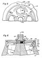
- Figure 5 is a plan view of a portion of the rotor of Figure 1 illustrating an alternate embodiment of the present invention.
- Figure 6 is a side elevation view, in section, illustrating the disposition of the spillage containment groove in accordance with the present invention in a rotor having an annular containment lip machined therein.
- FIG. 1 shown in side elevational view entirely in section is a portion of a centrifuge rotor 10 in accordance with the present invention.
- the rotor 10 is defined by a relatively massive body portion 12 formed from a high strength material such as titanium.
- the rotor body 12 has a planar upper surface 12U extending peripherally about the open top of the rotor.
- the radially outer peripheral edge of the upper surface 12U of the body of the rotor 10 defines an upstanding rim 12R.
- the rotor 10 is connected by a suitable drive connection shown schematically at 14 to a motive source M whereby motive energy may be applied to the rotor 10 to cause the same to rotate about the axis of rotation VCL in a manner understood by those skilled in the art.
- a motive source M whereby motive energy may be applied to the rotor 10 to cause the same to rotate about the axis of rotation VCL in a manner understood by those skilled in the art.
- the rotor discussed herein is designed for use in a ultracentrifuge instrument typically operated at a speed in excess of fifty thousand revolutions per minute it should be understood the present invention may be used with a rotor operable at any rotational speed.
- a plurality of cavities 18 is arranged in a substantially annular array in the body 12. Each of the cavities 18 is machined into the body 12 such that the axis 18A of each cavity defines a predetermined angle with respect to the axis of rotation VCL. Each of the cavities 18 is sized and configured to receive a container 20 (shown in Figures 2 through 4) carrying a sample of a liquid to be subjected to a centrifugal force field. Each of the containers 20 may be provided with a suitable capping assembly (now shown) whereby the contents of the container 20 is secured therewithin. The container 20 may nevertheless be susceptible to rupture due to stresses associated with high speed rotor operation. The capping assembly, if one is provided, may also be subject to leakage.
- the body 12 has an upstanding threaded boss 24 formed thereon.
- the boss 24 may receive a threaded core 26 about which an annular disc-like cover 28 is received.
- a seal 27 is trapped between the cover 28 and the core 26.
- a seal 29 extends about periphery of the cover 28.
- a cover clamp 30 with a washer 31 is threaded to the core 26 thereby to secure the cover 28 in position over the body 12 of the rotor with the edge of the cover 28 engaging the rim 12R, as shown in the Figures. Details of the cover and its mounting arrangement are disclosed in US-A 3,819,111, which is hereby incorporated by reference herein.
- the container and/or capping assembly (if one is provided) have a susceptibility for rupture or leakage. As a result there is a possibility for liquid to be liberated within the rotor during a centrifugation run. Unless precautions are taken this liquid may contaminate the remaining containers and/or cavities of the rotor.
- a spillage containment groove 38 is disposed in the body 12 of the rotor 10.
- the groove 38 is a continuous annular trench-like region extending completely about the interior of the body 12 near the upper surface 12U and radially outwardly of the cavities 18.
- the groove 38 is formed in any convenient manner, as by machining.
- the groove 38 is defined by a pair of radially spaced outer and inner walls 40A and 40B, respectively. The lower edges of the walls are joined by a contiguous bottom wall 42.
- the walls 40A and 40B may lie at the same predetermined angle with respect to the axis of rotation as do the cavities 18.
- the groove 38 need not extend in a concentric circular configuration.
- the groove 38 although continuous, may extend sinuously about the periphery of the body of the rotor, so long as the groove 38 surrounds the radially outer peripheral portions of the cavities 18.
- the groove 38 extend continuously about the interior of the rotor.
- Each groove segment 38 ⁇ is disposed radially outwardly of the mount of one of the cavities 18. With such an arrangement each groove segment 38 ⁇ serves to guard the mouth of the cavity 18 about which it is disposed and to prevent the entry of liquid thereinto.
- auxiliary recesses 44 may be bored into the body of the rotor in a manner whereby the recesses 44 communicate with the groove 38.
- the recesses 44 are angularly spaced about the body 12 of the rotor 10.
- the groove 38 is sized to receive a predetermined volume of liquid for a purpose more fully explained herein.
- the presence of the optional recesses 44 further enlarges the available volumetric capacity of the groove 38.
- each of the containers 20 is inserted into is associated cavity 18 in the body 12 of the rotor 10.
- the container 20 may be capped, as discussed, or may be simply inserted into the rotor in an uncapped condition. In the latter event the operator must be careful to introduce into the container only a predetermined amount of liquid so that under maximum centrifugal force the upper edge of the liquid in a given container will not extend past the upper edge of the container.
- Figure 2 Such a condition is illustrated in Figure 2 where the position of the upper level of a proper volume of the liquid with the rotor at rest is shown in solid lines while the position of the proper volume of liquid at maximum rotational speed is shown in dot-dash lines.
- the operator may err when filling the container 20.
- a capping assembly if one is provided, may be improperly secured to the container 20, or may leak. It could also occur that the container 20 itself may rupture. From whatever the source there may be a situation in which liquid is liberated within the rotor. In such an event the liquid is urged by centrifugal force radially outwardly to occupy a position such as shown at 48 in Figure 3. The liquid is confined within the rotor by the action of the cover 28.
- the present invention may be used with a rotor of the type in which a containment lip 52 is provided circumferentially about the rotor.
- the lip 52 serves the same purpose as the cover, i.e., confinement of the liberated liquid on the interior of the rotor, but this purpose is effected without exposing the cover itself to pressure or loading due to the liquid.
- the action of the groove 38 is the same. As the liquid drains the groove 38 collects the liquid and prevents its entry into the cavities of the rotor.
- the structure of the rotor in accordance with the present provides a suitably sized and configured spillage containment groove, either in a continuous or segmented arrangement, whereby any liquid present in the rotor from whatever the cause may be contained to prevent the deleterious effects of contamination thereby.
Landscapes
- Centrifugal Separators (AREA)
Claims (9)
- Zentrifugenrotor mit einer vertikalen Drehachse, mit einem Körperteil (12) mit wenigstens einer darin ausgebildeten Ausnehmung (18), wobei die Ausnehmung zur Aufnahme eines Behälters (20) bemessen ist, der eine Flüssigkeitsprobe enthält, und mit einer Nut (38), die radial außerhalb des oberen Endes der Ausnehmung (18) angeordnet und an ihrem oberen Ende zur Fluidverbindung mit der Ausnehmung (18) vorgesehen ist,
dadurch gekennzeichnet, daß
das obere Ende der Nut (38) eine offene Verbindung mit der Ausnehmung (18) zur direkten Fluidverbindung mit dieser unter statischen Bedingungen aufweist, wodurch ermöglicht ist, daß jegliche während des Betriebs der Zentrifuge aus dem Behälter (20) ausgetretene Flüssigkeit in die Nut (38) abfließt, wenn der Rotor (10) sich zum Anhalten verlangsamt. - Zentrifugenrotor nach Anspruch 1, bei dem eine ringförmige Anordnung von Ausnehmungen (18) in dem Rotorkörper (12) ausgebildet ist, wobei die Nut (38) radial außerhalb der Ausnehmungen (18) angeordnet ist.
- Zentrifugenrotor nach Anspruch 1 oder 2, ferner mit einer in dem Körper (12) des Rotors ausgebildeten Vertiefung (44), die in Verbindung mit der Nut steht.
- Zentrifugenrotor nach einem der Ansprüche 1 bis 3, bei dem die Nut (38) ringförmig um das Innere des Rotors (10) angeordnet ist.
- Zentrifugenrotor nach einem der Ansprüche 1 bis 4, bei dem das obere Ende der Ausnehmung (18) von einer Abdeckung (28) abgedeckt ist, deren Unterseite derart ausgebildet ist, daß jegliche in den Rotor ausgetretene Flüssigkeit durch die Wirkung der Abdeckung (28) in der Nut (38) zurückgehalten wird.
- Zentrifugenrotor nach einem der Ansprüche 1 bis 4, bei dem das Körperteil (12) durch eine Abdeckung (28) abgedeckt ist, wobei das Körperteil (12) am oberen Ende eine Lippe (52) aufweist, die derart ausgebildet ist, daß jegliche in den Rotor ausgetretene Flüssigkeit durch die Wirkung der Lippe (52) in der Nut (38) zurückgehalten wird.
- Zentrifugenrotor nach einem der Ansprüche 1 bis 6, bei dem die Nut (38) durchgehend ist.
- Zentrifugenrotor nach einem der Ansprüche 1 bis 7, bei dem die Nut mehrere nicht durchgehende Nutsegmente (38') umfaßt.
- Zentrifugenrotor nach einem der Ansprüche 1 bis 8, bei dem jede Nut (38) oder jedes Nutsegment (38') durch zwei radial beabstandete Seitenwände (40A, 40B) gebildet ist, die durch eine anschließende Bodenwand (42) miteinander verbunden sind, wobei die Bodenwand (42) wenigstens eine darin angeordnete Vertiefung (44) aufweist, um dadurch die volumetrische Kapazität der Nut zu vergrößern.
Priority Applications (1)
| Application Number | Priority Date | Filing Date | Title |
|---|---|---|---|
| AT87111160T ATE61010T1 (de) | 1986-08-04 | 1987-08-01 | Zentrifugenrotor mit ueberlaufrinne. |
Applications Claiming Priority (2)
| Application Number | Priority Date | Filing Date | Title |
|---|---|---|---|
| US892263 | 1986-08-04 | ||
| US06/892,263 US5071402A (en) | 1986-08-04 | 1986-08-04 | Centrifuge rotor having spillage containment groove |
Publications (3)
| Publication Number | Publication Date |
|---|---|
| EP0258652A2 EP0258652A2 (de) | 1988-03-09 |
| EP0258652A3 EP0258652A3 (en) | 1988-06-22 |
| EP0258652B1 true EP0258652B1 (de) | 1991-02-27 |
Family
ID=25399677
Family Applications (1)
| Application Number | Title | Priority Date | Filing Date |
|---|---|---|---|
| EP87111160A Expired - Lifetime EP0258652B1 (de) | 1986-08-04 | 1987-08-01 | Zentrifugenrotor mit Überlaufrinne |
Country Status (8)
| Country | Link |
|---|---|
| US (1) | US5071402A (de) |
| EP (1) | EP0258652B1 (de) |
| JP (1) | JPH084765B2 (de) |
| AT (1) | ATE61010T1 (de) |
| CA (1) | CA1302994C (de) |
| DE (1) | DE3768182D1 (de) |
| ES (1) | ES2020975B3 (de) |
| GR (1) | GR3001524T3 (de) |
Cited By (1)
| Publication number | Priority date | Publication date | Assignee | Title |
|---|---|---|---|---|
| CN105102957A (zh) * | 2013-04-09 | 2015-11-25 | 樱花精机株式会社 | 离心涂抹装置及密闭旋转容器 |
Families Citing this family (18)
| Publication number | Priority date | Publication date | Assignee | Title |
|---|---|---|---|---|
| JPH01179751U (de) * | 1988-06-03 | 1989-12-25 | ||
| GB2233584B (en) * | 1989-07-01 | 1994-03-09 | Robert Anthony Kerby | Centrifuge rotors |
| US5266268A (en) * | 1991-08-15 | 1993-11-30 | Iniziative Maritime 1991, S.R.L. | Centrifugal analyzer rotors |
| US5562554A (en) * | 1992-10-09 | 1996-10-08 | E. I. Du Pont De Nemours And Company | Centrifuge rotor having a fused web |
| US5529567A (en) * | 1994-07-01 | 1996-06-25 | Baxter International Inc. | Blood processing system having spill sensor with fail-safe circuit |
| US5484381A (en) * | 1994-10-26 | 1996-01-16 | E. I. Du Pont De Nemours And Company | Centrifuge rotor having liquid-capturing holes |
| US5512030A (en) * | 1994-12-01 | 1996-04-30 | E. I. Du Pont De Nemours And Company | Centrifuge rotor |
| US5840005A (en) * | 1996-09-26 | 1998-11-24 | Beckman Instruments, Inc. | Centrifuge with inertial mass relief |
| DE19723613B4 (de) * | 1997-06-05 | 2004-08-05 | Kendro Laboratory Products Gmbh | Rotor für Laborzentrifugen |
| US20050054506A1 (en) * | 2003-07-30 | 2005-03-10 | Bradley Bruce J. | Microbial concentration system |
| US9149815B2 (en) * | 2006-05-23 | 2015-10-06 | Eppendorf Ag | Lid for closing a centrifuge rotor |
| US7837607B2 (en) * | 2006-12-13 | 2010-11-23 | Thermo Fisher Scientific Inc. | Centrifuge rotor assembly and method of connection thereof |
| JP4862711B2 (ja) * | 2007-03-20 | 2012-01-25 | 日立工機株式会社 | 遠心分離機用ロータ及び遠心分離機 |
| EP2269740B1 (de) * | 2009-06-30 | 2015-11-04 | Hitachi Koki CO., LTD. | Zentrifugalabscheider |
| JP5333759B2 (ja) * | 2009-06-30 | 2013-11-06 | 日立工機株式会社 | 遠心分離機 |
| US10086383B2 (en) * | 2015-01-05 | 2018-10-02 | Fiberlite Centrifuge, Llc | Fixed angle centrifuge rotor having torque transfer members |
| US10352282B2 (en) | 2015-09-01 | 2019-07-16 | Corey Jay COLVIN | Hydraulic union ball tube with leak diffusion |
| DE102017130787A1 (de) * | 2017-12-20 | 2019-06-27 | Eppendorf Ag | Zentrifugenrotor |
Family Cites Families (10)
| Publication number | Priority date | Publication date | Assignee | Title |
|---|---|---|---|---|
| DE1912322C3 (de) * | 1969-03-11 | 1974-10-17 | Fa. Andreas Hettich, 7200 Tuttlingen | Gefaßträger für Zentrifugen |
| US3586484A (en) * | 1969-05-23 | 1971-06-22 | Atomic Energy Commission | Multistation analytical photometer and method of use |
| US3863049A (en) * | 1972-05-31 | 1975-01-28 | Union Carbide Corp | Temperature control apparatus for a centrifugal-type chemistry analyzer |
| US3819111A (en) * | 1973-04-09 | 1974-06-25 | Sorvall Inc Ivan | Centrifuge rotor cover |
| US3901434A (en) * | 1973-10-10 | 1975-08-26 | Beckman Instruments Inc | Non-extruding lid seal for centrifuges |
| US4202487A (en) * | 1978-02-22 | 1980-05-13 | Beckman Instruments, Inc. | Lipoprotein rotor lid |
| US4360151A (en) * | 1980-07-01 | 1982-11-23 | Beckman Instruments, Inc. | Aerosol resistant bowl rotor |
| US4372483A (en) * | 1981-05-29 | 1983-02-08 | Beckman Instruments, Inc. | Fluid containment annulus for fixed angle rotors |
| US4375272A (en) * | 1981-07-01 | 1983-03-01 | Beckman Instruments, Inc. | Fixed angle tube carrier |
| US4484906A (en) * | 1983-05-02 | 1984-11-27 | Beckman Instruments, Inc. | Shell type centrifuge rotor retaining ruptured tube sample |
-
1986
- 1986-08-04 US US06/892,263 patent/US5071402A/en not_active Expired - Lifetime
-
1987
- 1987-07-28 CA CA000543161A patent/CA1302994C/en not_active Expired - Lifetime
- 1987-08-01 DE DE8787111160T patent/DE3768182D1/de not_active Expired - Lifetime
- 1987-08-01 ES ES87111160T patent/ES2020975B3/es not_active Expired - Lifetime
- 1987-08-01 AT AT87111160T patent/ATE61010T1/de not_active IP Right Cessation
- 1987-08-01 EP EP87111160A patent/EP0258652B1/de not_active Expired - Lifetime
- 1987-08-03 JP JP62192761A patent/JPH084765B2/ja not_active Expired - Lifetime
-
1991
- 1991-02-28 GR GR91400131T patent/GR3001524T3/el unknown
Cited By (2)
| Publication number | Priority date | Publication date | Assignee | Title |
|---|---|---|---|---|
| CN105102957A (zh) * | 2013-04-09 | 2015-11-25 | 樱花精机株式会社 | 离心涂抹装置及密闭旋转容器 |
| CN105102957B (zh) * | 2013-04-09 | 2017-09-26 | 樱花精机株式会社 | 离心涂抹装置及密闭旋转容器 |
Also Published As
| Publication number | Publication date |
|---|---|
| ES2020975B3 (es) | 1991-10-16 |
| JPH084765B2 (ja) | 1996-01-24 |
| US5071402A (en) | 1991-12-10 |
| CA1302994C (en) | 1992-06-09 |
| JPS6342755A (ja) | 1988-02-23 |
| GR3001524T3 (en) | 1992-11-23 |
| EP0258652A3 (en) | 1988-06-22 |
| DE3768182D1 (de) | 1991-04-04 |
| EP0258652A2 (de) | 1988-03-09 |
| ATE61010T1 (de) | 1991-03-15 |
Similar Documents
| Publication | Publication Date | Title |
|---|---|---|
| EP0258652B1 (de) | Zentrifugenrotor mit Überlaufrinne | |
| US4360151A (en) | Aerosol resistant bowl rotor | |
| US4177921A (en) | One piece chylomicron rotor liner | |
| US6149570A (en) | Self-retaining rotor lid | |
| JP3554018B2 (ja) | 遠心分離機 | |
| US4451250A (en) | Inside adapter for a sample container | |
| US4372483A (en) | Fluid containment annulus for fixed angle rotors | |
| US4087043A (en) | Dual seal arrangement for a centrifuge rotor tube cavity | |
| IE46019B1 (en) | Centrifuge rotor | |
| US3905528A (en) | Two-piece concentric centrifuge sample container | |
| US5901873A (en) | Self-seating self-sealing labware adapter | |
| US4166573A (en) | Centrifuge tube enclosure | |
| JP3431236B2 (ja) | 遠心分離機のロータ | |
| EP0368173A2 (de) | Abdichtungsvorrichtung für Rotorausnehmungen eines Zentrifugenrotors | |
| US4235367A (en) | Secondary centrifuge tube seal | |
| US5484381A (en) | Centrifuge rotor having liquid-capturing holes | |
| US5487719A (en) | Centrifuge rotor assembly | |
| US20230294112A1 (en) | Rotor with improved spill control | |
| WO1992011092A1 (en) | Centrifuge bottle having a canted neck | |
| CN116764828A (zh) | 具有改进的溢出控制的转子 | |
| EP4245419A1 (de) | Rotor mit verbesserter auslaufsteuerung | |
| JPS5826022Y2 (ja) | 遠心分離ロ−タ | |
| JPH01310755A (ja) | 遠心清澄機の封水装置 | |
| GB2194904A (en) | Improvements relating to centrifuges | |
| JPH03224647A (ja) | 遠心清澄機の封水装置 |
Legal Events
| Date | Code | Title | Description |
|---|---|---|---|
| PUAI | Public reference made under article 153(3) epc to a published international application that has entered the european phase |
Free format text: ORIGINAL CODE: 0009012 |
|
| AK | Designated contracting states |
Kind code of ref document: A2 Designated state(s): AT BE CH DE ES FR GB GR IT LI LU NL SE |
|
| PUAL | Search report despatched |
Free format text: ORIGINAL CODE: 0009013 |
|
| AK | Designated contracting states |
Kind code of ref document: A3 Designated state(s): AT BE CH DE ES FR GB GR IT LI LU NL SE |
|
| 17P | Request for examination filed |
Effective date: 19880527 |
|
| 17Q | First examination report despatched |
Effective date: 19890106 |
|
| GRAA | (expected) grant |
Free format text: ORIGINAL CODE: 0009210 |
|
| AK | Designated contracting states |
Kind code of ref document: B1 Designated state(s): AT BE CH DE ES FR GB GR IT LI LU NL SE |
|
| REF | Corresponds to: |
Ref document number: 61010 Country of ref document: AT Date of ref document: 19910315 Kind code of ref document: T |
|
| ITF | It: translation for a ep patent filed | ||
| ET | Fr: translation filed | ||
| REF | Corresponds to: |
Ref document number: 3768182 Country of ref document: DE Date of ref document: 19910404 |
|
| PLBE | No opposition filed within time limit |
Free format text: ORIGINAL CODE: 0009261 |
|
| STAA | Information on the status of an ep patent application or granted ep patent |
Free format text: STATUS: NO OPPOSITION FILED WITHIN TIME LIMIT |
|
| 26N | No opposition filed | ||
| REG | Reference to a national code |
Ref country code: GR Ref legal event code: FG4A Free format text: 3001524 |
|
| EPTA | Lu: last paid annual fee | ||
| EAL | Se: european patent in force in sweden |
Ref document number: 87111160.5 |
|
| PGFP | Annual fee paid to national office [announced via postgrant information from national office to epo] |
Ref country code: GR Payment date: 19960531 Year of fee payment: 10 |
|
| PGFP | Annual fee paid to national office [announced via postgrant information from national office to epo] |
Ref country code: LU Payment date: 19960601 Year of fee payment: 10 |
|
| PGFP | Annual fee paid to national office [announced via postgrant information from national office to epo] |
Ref country code: NL Payment date: 19960610 Year of fee payment: 10 Ref country code: BE Payment date: 19960610 Year of fee payment: 10 |
|
| PGFP | Annual fee paid to national office [announced via postgrant information from national office to epo] |
Ref country code: GB Payment date: 19960620 Year of fee payment: 10 |
|
| PGFP | Annual fee paid to national office [announced via postgrant information from national office to epo] |
Ref country code: AT Payment date: 19960710 Year of fee payment: 10 |
|
| PGFP | Annual fee paid to national office [announced via postgrant information from national office to epo] |
Ref country code: SE Payment date: 19960711 Year of fee payment: 10 |
|
| PGFP | Annual fee paid to national office [announced via postgrant information from national office to epo] |
Ref country code: CH Payment date: 19960715 Year of fee payment: 10 |
|
| PGFP | Annual fee paid to national office [announced via postgrant information from national office to epo] |
Ref country code: ES Payment date: 19960807 Year of fee payment: 10 |
|
| PG25 | Lapsed in a contracting state [announced via postgrant information from national office to epo] |
Ref country code: LU Free format text: LAPSE BECAUSE OF NON-PAYMENT OF DUE FEES Effective date: 19970801 Ref country code: GB Free format text: LAPSE BECAUSE OF NON-PAYMENT OF DUE FEES Effective date: 19970801 Ref country code: AT Free format text: LAPSE BECAUSE OF NON-PAYMENT OF DUE FEES Effective date: 19970801 |
|
| PG25 | Lapsed in a contracting state [announced via postgrant information from national office to epo] |
Ref country code: SE Free format text: LAPSE BECAUSE OF NON-PAYMENT OF DUE FEES Effective date: 19970802 Ref country code: ES Free format text: LAPSE BECAUSE OF EXPIRATION OF PROTECTION Effective date: 19970802 |
|
| PG25 | Lapsed in a contracting state [announced via postgrant information from national office to epo] |
Ref country code: LI Free format text: LAPSE BECAUSE OF NON-PAYMENT OF DUE FEES Effective date: 19970831 Ref country code: GR Free format text: LAPSE BECAUSE OF NON-PAYMENT OF DUE FEES Effective date: 19970831 Ref country code: CH Free format text: LAPSE BECAUSE OF NON-PAYMENT OF DUE FEES Effective date: 19970831 Ref country code: BE Free format text: LAPSE BECAUSE OF NON-PAYMENT OF DUE FEES Effective date: 19970831 |
|
| BERE | Be: lapsed |
Owner name: E.I. DU PONT DE NEMOURS AND CY Effective date: 19970831 |
|
| PG25 | Lapsed in a contracting state [announced via postgrant information from national office to epo] |
Ref country code: NL Free format text: LAPSE BECAUSE OF NON-PAYMENT OF DUE FEES Effective date: 19980301 |
|
| GBPC | Gb: european patent ceased through non-payment of renewal fee |
Effective date: 19970801 |
|
| REG | Reference to a national code |
Ref country code: CH Ref legal event code: PL |
|
| EUG | Se: european patent has lapsed |
Ref document number: 87111160.5 |
|
| NLV4 | Nl: lapsed or anulled due to non-payment of the annual fee |
Effective date: 19980301 |
|
| REG | Reference to a national code |
Ref country code: ES Ref legal event code: FD2A Effective date: 20010201 |
|
| PGFP | Annual fee paid to national office [announced via postgrant information from national office to epo] |
Ref country code: FR Payment date: 20010810 Year of fee payment: 15 |
|
| PGFP | Annual fee paid to national office [announced via postgrant information from national office to epo] |
Ref country code: DE Payment date: 20020830 Year of fee payment: 16 |
|
| PG25 | Lapsed in a contracting state [announced via postgrant information from national office to epo] |
Ref country code: FR Free format text: LAPSE BECAUSE OF NON-PAYMENT OF DUE FEES Effective date: 20030430 |
|
| REG | Reference to a national code |
Ref country code: FR Ref legal event code: ST |
|
| PG25 | Lapsed in a contracting state [announced via postgrant information from national office to epo] |
Ref country code: DE Free format text: LAPSE BECAUSE OF NON-PAYMENT OF DUE FEES Effective date: 20040302 |
|
| PG25 | Lapsed in a contracting state [announced via postgrant information from national office to epo] |
Ref country code: IT Free format text: LAPSE BECAUSE OF NON-PAYMENT OF DUE FEES;WARNING: LAPSES OF ITALIAN PATENTS WITH EFFECTIVE DATE BEFORE 2007 MAY HAVE OCCURRED AT ANY TIME BEFORE 2007. THE CORRECT EFFECTIVE DATE MAY BE DIFFERENT FROM THE ONE RECORDED. Effective date: 20050801 |