EP0258518A2 - Orbital sander - Google Patents
Orbital sander Download PDFInfo
- Publication number
- EP0258518A2 EP0258518A2 EP87100796A EP87100796A EP0258518A2 EP 0258518 A2 EP0258518 A2 EP 0258518A2 EP 87100796 A EP87100796 A EP 87100796A EP 87100796 A EP87100796 A EP 87100796A EP 0258518 A2 EP0258518 A2 EP 0258518A2
- Authority
- EP
- European Patent Office
- Prior art keywords
- drive
- orbital sander
- outer wheel
- sun gear
- planetary gear
- Prior art date
- Legal status (The legal status is an assumption and is not a legal conclusion. Google has not performed a legal analysis and makes no representation as to the accuracy of the status listed.)
- Granted
Links
- 238000009434 installation Methods 0.000 abstract description 3
- 230000005540 biological transmission Effects 0.000 description 1
- 238000011161 development Methods 0.000 description 1
- 230000018109 developmental process Effects 0.000 description 1
Images


Classifications
-
- F—MECHANICAL ENGINEERING; LIGHTING; HEATING; WEAPONS; BLASTING
- F16—ENGINEERING ELEMENTS AND UNITS; GENERAL MEASURES FOR PRODUCING AND MAINTAINING EFFECTIVE FUNCTIONING OF MACHINES OR INSTALLATIONS; THERMAL INSULATION IN GENERAL
- F16H—GEARING
- F16H21/00—Gearings comprising primarily only links or levers, with or without slides
- F16H21/10—Gearings comprising primarily only links or levers, with or without slides all movement being in, or parallel to, a single plane
- F16H21/16—Gearings comprising primarily only links or levers, with or without slides all movement being in, or parallel to, a single plane for interconverting rotary motion and reciprocating motion
- F16H21/18—Crank gearings; Eccentric gearings
- F16H21/36—Crank gearings; Eccentric gearings without swinging connecting-rod, e.g. with epicyclic parallel motion, slot-and-crank motion
-
- B—PERFORMING OPERATIONS; TRANSPORTING
- B24—GRINDING; POLISHING
- B24B—MACHINES, DEVICES, OR PROCESSES FOR GRINDING OR POLISHING; DRESSING OR CONDITIONING OF ABRADING SURFACES; FEEDING OF GRINDING, POLISHING, OR LAPPING AGENTS
- B24B23/00—Portable grinding machines, e.g. hand-guided; Accessories therefor
- B24B23/04—Portable grinding machines, e.g. hand-guided; Accessories therefor with oscillating grinding tools; Accessories therefor
Definitions
- the invention relates to an orbital sander according to the preamble of patent claim 1.
- Such orbital grinders usually have no reduction gear between the armature shaft of the drive motor and the drive shaft of the grinding plate, so that the armature shaft and drive shaft are identical.
- orbital sanders of the generic type have also become known, in which the number of wires of the drive motor is reduced by means of a conventional gear and the number of vibrations of the grinding plate is reduced accordingly.
- the gearboxes used for this purpose require a not inconsiderable installation volume, and they are also expensive.
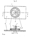
- the asymmetrical planetary gear shown schematically in Figures 1 to 3 contains a sun gear 2 attached to the armature or drive shaft 1 of the drive motor, not shown, with which three planet gears 4, 5 and 6 meshing with the internal teeth of the outer gear 3 mesh.
- the wheel 4 has a larger diameter than the other two gears 5 and 6.
- the sun gear 2 rotates, the three planet gears roll on it and on the internal toothing of the outer gear 3, which may also be elastically deformable to a limited extent .
- the outer wheel 3 performs a rotary movement about the axis 1 ⁇ of the drive shaft lying eccentrically to its center M.
- the movement of the eccentric embodied by the outer wheel 3 is transmitted, as can be seen from FIGS. 5 and 6, to the grinding plate 8, which has a circular recess 9 into which the outer wheel 3, which is mechanically firmly connected to the grinding plate, engages.
- the reduction of the speed of the drive shaft according to the invention enables a considerable increase in the speed of the drive motor and thus, with the same motor size, also an increase in the drive power.
- friction wheels can also be provided, including the sun gear 2. If necessary, regardless of whether a planetary gear with gearwheels or friction wheels is used, only two planet wheels with different diameters can be provided.
Landscapes
- Engineering & Computer Science (AREA)
- General Engineering & Computer Science (AREA)
- Mechanical Engineering (AREA)
- Finish Polishing, Edge Sharpening, And Grinding By Specific Grinding Devices (AREA)
- Retarders (AREA)
- Connection Of Motors, Electrical Generators, Mechanical Devices, And The Like (AREA)
Abstract
Um bei einem Schwingschleifer mit einer über elastische Elemente abgestützten Schleifplatte, die mittels eines durch die Ankerwelle des Antriebsmotors in Drehung versetzbaren Antriebsexzenters in eine Hin- und Herbewegung versetzbar ist, mit einem Geringstmaß an Einbauvolumen und Aufwand eine in einem weiten Bereich wählbare Untersetzung der Ankerwellendrehzahl zu ermöglichen, wird vorgeschlagen, den Antriebsexzenter als Außenrad (3) eines asymmetrischen Planetengetriebes mit auf der Antriebswelle (1) angeordnetem Sonnenrad (2) auszubilden (Fig. 1).In the case of an orbital sander with a grinding plate supported by elastic elements, which can be set in a reciprocating motion by means of a drive eccentric that can be rotated by the armature shaft of the drive motor, a reduction in the armature shaft speed that can be selected in a wide range is achieved with a minimal amount of installation volume and effort enable, it is proposed to design the drive eccentric as an outer wheel (3) of an asymmetrical planetary gear with a sun wheel (2) arranged on the drive shaft (1) (FIG. 1).
Description
Die Erfindung betrifft einen Schwingschleifer nach dem Oberbegriff des Patentanspruchs 1.The invention relates to an orbital sander according to the preamble of
Derartige Schwingschleifer weisen meist kein Untersetzungsgetriebe zwischen der Ankerwelle des Antriebsmotors und der Antriebswelle der Schleifplatte auf, so daß Ankerwelle und Antriebswelle identisch sind.Such orbital grinders usually have no reduction gear between the armature shaft of the drive motor and the drive shaft of the grinding plate, so that the armature shaft and drive shaft are identical.
Es sind jedoch auch schon Schwingschleifer der gattungsgemäßen Art bekannt geworden, bei denen die Drahzahl des Antriebsmotors mittels eines herkömmlichen Getriebes untersetzt und dementsprechend die Schwingungszahl der Schleifplatte reduziert ist. Die für diesen Zweck verwendeten Getriebe beanspruchen jedoch ein nicht unerhebliches Einbauvolumen, außerdem sind sie kostenaufwendig.However, orbital sanders of the generic type have also become known, in which the number of wires of the drive motor is reduced by means of a conventional gear and the number of vibrations of the grinding plate is reduced accordingly. However, the gearboxes used for this purpose require a not inconsiderable installation volume, and they are also expensive.
Es ist Aufgabe der Erfindung, eine Getriebekonzeption zu finden, die mit einem Geringstmaß an Einbauvolumen und Kosten eine in einem relativ weiten Bereich wählbare Untersetzung der Drehzahl der Ankerwelle des Antriebsmotors ermöglicht.It is an object of the invention to find a transmission concept which, with a minimal amount of installation volume and costs, enables the speed of the armature shaft of the drive motor to be reduced in a relatively wide range.
Diese Aufgabe ist erfindungsgemäß mit den kennzeichnenden Merkmalen des Patentanspruchs 1 gelöst.This object is achieved with the characterizing features of
Mit dieser Maßnahme ist erreicht, daß Getriebe und Exzenter eine Baueinheit bilden, die kompakt und preisgünstig ist. Weiterbildungen und zweckmäßige Ausgestaltungen der Erfindung sind in den Unteransprüchen angegeben.This measure ensures that the gear and eccentric form a structural unit that is compact and inexpensive. Further developments and expedient refinements of the invention are specified in the subclaims.
Die Erfindung wird im nachstehenden anhand der Zeichnung, de ein Ausführungsbeispiel mit drei Planetenrädern schematisch veranschaulicht, erläutert.The invention is explained below with reference to the drawing, which schematically illustrates an embodiment with three planet gears.
Es zeigen:
- Fig. 1 bis 3: die Anordnung und den Aufbau des asymmetrischen Getriebes bei verschiedenen Positionen der Planetenräder,
- Fig. 4 : Die Umlaufbewegung des Außenrades,
- Fig. 5 : eine Draufsicht auf das Planetengretriebe mit Schleifplatte,
- Fig. 6 : eine Ansicht längs des Schnitts A-B durch Fig. 5
- 1 to 3: the arrangement and structure of the asymmetrical gear in different positions of the planet gears,
- 4: The orbital movement of the outer wheel,
- 5: a top view of the planetary gear with grinding plate,
- 6 shows a view along the section AB through FIG. 5
Das in den Figuren 1 bis 3 schematisch dargestellte asymmetrische Planetengetriebe enthält ein auf der Anker- bzw. der Antriebswelle 1 des nicht gezeichneten Antriebsmotors angebrachtes Sonnenrad 2, mit dem drei in die Innenverzahnung des Außenrads 3 eingreifende Planetenräder 4,5 und 6 kämmen. Von diesen drei Planetenrädern weist das Rad 4 einen größeren Durchmesser auf als die beiden anderen Räder 5 und 6. Bei Drehung des Sonnenrads 2 rollen die drei Planetenräder auf diesem und der Innenverzahnung des Außenrads 3, das gegebenenfalls in Grenzen auch elastische verformbar sein kann, ab. Wegen der unterschiedlichen Größen der Planetenräder und der ortsunveränderlichen Antriebswelle 1 führt das Außenrad 3 eine Drehbewegung um die exzentrisch zu seinem Mittelpunkt M liegende Achse 1ʹ der Antriebswelle aus. Infolge dieser Exzenterbewegung ergibt sich auch in Längsrichtung (siehe Doppelpfeil) bezogen auf die "Aus gangsposition" gemäß Figur 1 (Mittellinie 7) ein positiver und negativer Hub e und insgesamt gesehen eine Umlaufbewegung des Außenrads 3, wie sie im Prinzip in Fig. 4 dargestellt ist. Die Ausgangsposition des Außenrads 3 entspricht dabei dergenigen nach Fig. 1 (0°/360°).The asymmetrical planetary gear shown schematically in Figures 1 to 3 contains a
Die Bewegung des durch das Außenrad 3 verkörperten Exzenters wird, wie aus den Fig. 5 und 6 ersichtlich ist, auf die Schleifplatte 8 übertragen, die eine kreisförmige Ausnehmung 9 aufweist, in welche das mechanisch fest mit der Schleifplatte verbundene Außenrad 3 eingreift.The movement of the eccentric embodied by the
Die erfindungsgemäße Untersetzung der Drehzahl der Antriebswelle ermöglicht eine beträchtliche Erhöhung der Drehzahl des Antriebsmotors und damit bei gleicher Motorbaugröße auch eine Steigerung der Antriebsleistung.The reduction of the speed of the drive shaft according to the invention enables a considerable increase in the speed of the drive motor and thus, with the same motor size, also an increase in the drive power.
Anstelle eines Planetenantriebs mit Zahnrädern gleichen Moduls können auch Reibräder vorgesehen sein, und zwar einschließlich des Sonnenrads 2. Gegebenenfalls können unabhängig davon, ob ein Planetengetriebe mit Zahnrädern oder Reibrädern benutzt wird, jeweils auch nur zwei Planetenräder mit unterschiedlichem Durchmesser vorgesehen sein.Instead of a planetary drive with gearwheels of the same module, friction wheels can also be provided, including the
Claims (4)
Applications Claiming Priority (2)
| Application Number | Priority Date | Filing Date | Title |
|---|---|---|---|
| DE3630155 | 1986-09-04 | ||
| DE19863630155 DE3630155A1 (en) | 1986-09-04 | 1986-09-04 | ORBITAL SANDER WITH A GRINDING PLATE SUPPORTED BY ELASTIC ELEMENTS |
Publications (3)
| Publication Number | Publication Date |
|---|---|
| EP0258518A2 true EP0258518A2 (en) | 1988-03-09 |
| EP0258518A3 EP0258518A3 (en) | 1988-07-06 |
| EP0258518B1 EP0258518B1 (en) | 1990-06-27 |
Family
ID=6308934
Family Applications (1)
| Application Number | Title | Priority Date | Filing Date |
|---|---|---|---|
| EP87100796A Expired - Lifetime EP0258518B1 (en) | 1986-09-04 | 1987-01-21 | Orbital sander |
Country Status (3)
| Country | Link |
|---|---|
| US (1) | US4845898A (en) |
| EP (1) | EP0258518B1 (en) |
| DE (2) | DE3630155A1 (en) |
Cited By (2)
| Publication number | Priority date | Publication date | Assignee | Title |
|---|---|---|---|---|
| EP2128490A3 (en) * | 2008-05-27 | 2012-04-18 | Robert Bosch GmbH | Excentric planetary gearing |
| ITRE20130022A1 (en) * | 2013-03-26 | 2014-09-27 | Lorenzo Segapeli | APPARATUS FOR IMPROVING ROUGH WORKING; GRINDING; POLISH; BRUSHING LAPPING OF SURFACES OF STONE MATERIALS; CERAMIC PRODUCTS; GRES; GRESSMALTATO COMPOSITI VARIOUS |
Families Citing this family (11)
| Publication number | Priority date | Publication date | Assignee | Title |
|---|---|---|---|---|
| US7004818B1 (en) | 1990-08-17 | 2006-02-28 | Haney Donald E | Sander with orbiting platen and abrasive |
| US5081794A (en) | 1990-08-17 | 1992-01-21 | Haney Donald E | Sander with orbiting platen and abrasive |
| US6009767A (en) * | 1998-04-23 | 2000-01-04 | Rudolph; Gary | Same-RPM rotary motion to eccentric rotary motion conversion |
| US7198557B2 (en) * | 2001-08-02 | 2007-04-03 | Haney Donald E | Sanding machine incorporating multiple sanding motions |
| US7220174B2 (en) * | 2004-09-29 | 2007-05-22 | Black & Decker Inc. | Drywall sander |
| KR100796347B1 (en) | 2006-07-21 | 2008-01-21 | 가부시키 가이샤 메쿠스 | Mobile device and planetary polishing machine using planetary gear mechanism |
| RU2365799C2 (en) * | 2007-07-16 | 2009-08-27 | Государственное образовательное учреждение высшего профессионального образования Курганский государственный университет | Geared linkage rotation to reciprocation transformer |
| US20090204061A1 (en) * | 2008-02-12 | 2009-08-13 | Bellecore, Llc | Method and apparatus for treating cellulite |
| DE102010046629A1 (en) | 2010-09-17 | 2012-03-22 | C. & E. Fein Gmbh | hand tool |
| CN104308684A (en) * | 2014-10-31 | 2015-01-28 | 浙江丽佳建筑装饰工程有限公司 | Grinding machine with centrifugal fan for building walls |
| CN104308683A (en) * | 2014-10-31 | 2015-01-28 | 浙江丽佳建筑装饰工程有限公司 | Grinding machine for building walls |
Family Cites Families (9)
| Publication number | Priority date | Publication date | Assignee | Title |
|---|---|---|---|---|
| US1487466A (en) * | 1921-10-13 | 1924-03-18 | Albert L Norris | Rotary brush |
| US1667329A (en) * | 1925-10-12 | 1928-04-24 | Max M Menzel | Meat-block scraper and dresser |
| US3284961A (en) * | 1964-05-25 | 1966-11-15 | Buehler Ltd | Polishing device |
| US3287859A (en) * | 1965-08-23 | 1966-11-29 | Treffle J Leveque | Rotatable grinding and surfacing tool |
| DE2306876C2 (en) * | 1973-02-13 | 1982-04-29 | Robert Bosch Gmbh, 7000 Stuttgart | Orbital sander |
| US3857206A (en) * | 1973-03-08 | 1974-12-31 | Nat Detroit Inc Co | Compound motion rubbing machine |
| DE2316286A1 (en) * | 1973-03-31 | 1974-10-17 | Bosch Gmbh Robert | ORBITAL GRINDER |
| DE2349805A1 (en) * | 1973-10-04 | 1975-04-10 | Ernst Georg Haller | Reciprocating movement using hypo-cycloidal drive - produces stroke length greater than throw of driving crank |
| US4467565A (en) * | 1982-08-02 | 1984-08-28 | Chicago Pneumatic Tool Company | Rotary and orbital sander |
-
1986
- 1986-09-04 DE DE19863630155 patent/DE3630155A1/en not_active Withdrawn
-
1987
- 1987-01-21 EP EP87100796A patent/EP0258518B1/en not_active Expired - Lifetime
- 1987-01-21 DE DE8787100796T patent/DE3763376D1/en not_active Expired - Lifetime
- 1987-09-03 US US07/092,597 patent/US4845898A/en not_active Expired - Fee Related
Cited By (2)
| Publication number | Priority date | Publication date | Assignee | Title |
|---|---|---|---|---|
| EP2128490A3 (en) * | 2008-05-27 | 2012-04-18 | Robert Bosch GmbH | Excentric planetary gearing |
| ITRE20130022A1 (en) * | 2013-03-26 | 2014-09-27 | Lorenzo Segapeli | APPARATUS FOR IMPROVING ROUGH WORKING; GRINDING; POLISH; BRUSHING LAPPING OF SURFACES OF STONE MATERIALS; CERAMIC PRODUCTS; GRES; GRESSMALTATO COMPOSITI VARIOUS |
Also Published As
| Publication number | Publication date |
|---|---|
| DE3630155A1 (en) | 1988-03-10 |
| EP0258518A3 (en) | 1988-07-06 |
| DE3763376D1 (en) | 1990-08-02 |
| US4845898A (en) | 1989-07-11 |
| EP0258518B1 (en) | 1990-06-27 |
Similar Documents
| Publication | Publication Date | Title |
|---|---|---|
| EP0309508B1 (en) | Crank mechanism | |
| EP0258518B1 (en) | Orbital sander | |
| DE10059975A1 (en) | Hand tool | |
| EP0641621A1 (en) | Rotary drive device | |
| DE3512190A1 (en) | Grinding or brushing unit which is driven by an electric motor | |
| WO2000028238A1 (en) | Eccentric toothed gearing | |
| EP1099063B1 (en) | Engine-transmission unit | |
| DE3032587A1 (en) | Electric machine with epicycle gears for drive shaft - has gear units in hub supported on two hollow shafts | |
| EP0776432B1 (en) | Device for converting rotary motion into axial motion | |
| DE19716538A1 (en) | Electric hub drive | |
| DE2748918A1 (en) | Compact drive for extruder with conical twin screws - has worm-gear normal to axial plane of screws, to allow operating at low rotational speed | |
| DE2446839C3 (en) | Device for driving a wiper shaft of wiper devices on motor vehicles | |
| EP0175910B1 (en) | Circular saw | |
| DE4400887C2 (en) | Milling machine for processing ridge edges on the end faces of teeth of a gear wheel | |
| DE2919240C2 (en) | ||
| DE10254129B4 (en) | Electromotive furniture drive for adjusting parts of a furniture relative to each other | |
| DE10258863A1 (en) | Power tool, in particular angle grinder, comprising input arrangement designed as bevel gear and output arrangement designed as planetary gear | |
| EP0707541B1 (en) | Driving device for an adjustable part of a vehicle | |
| DE3620101A1 (en) | Drive arrangement | |
| DE1952664A1 (en) | Drive device for a gear drive, in particular a rack and pinion drive | |
| AT404918B (en) | DOUBLE CRANKSET | |
| EP1195302B1 (en) | Windscreen wiper device, in particular for a vehicle | |
| DE3643613A1 (en) | AXIAL DRIVE | |
| AT303478B (en) | Gear for converting a rotary motion into a slower rotary motion combined with a straight line motion | |
| DE2423905C3 (en) | Transmission with power split |
Legal Events
| Date | Code | Title | Description |
|---|---|---|---|
| PUAI | Public reference made under article 153(3) epc to a published international application that has entered the european phase |
Free format text: ORIGINAL CODE: 0009012 |
|
| 17P | Request for examination filed |
Effective date: 19870205 |
|
| AK | Designated contracting states |
Kind code of ref document: A2 Designated state(s): CH DE GB LI NL |
|
| PUAL | Search report despatched |
Free format text: ORIGINAL CODE: 0009013 |
|
| AK | Designated contracting states |
Kind code of ref document: A3 Designated state(s): CH DE GB LI NL |
|
| 17Q | First examination report despatched |
Effective date: 19891121 |
|
| GRAA | (expected) grant |
Free format text: ORIGINAL CODE: 0009210 |
|
| AK | Designated contracting states |
Kind code of ref document: B1 Designated state(s): CH DE GB LI NL |
|
| REF | Corresponds to: |
Ref document number: 3763376 Country of ref document: DE Date of ref document: 19900802 |
|
| GBT | Gb: translation of ep patent filed (gb section 77(6)(a)/1977) | ||
| PGFP | Annual fee paid to national office [announced via postgrant information from national office to epo] |
Ref country code: GB Payment date: 19901213 Year of fee payment: 5 |
|
| PGFP | Annual fee paid to national office [announced via postgrant information from national office to epo] |
Ref country code: NL Payment date: 19910131 Year of fee payment: 5 |
|
| PGFP | Annual fee paid to national office [announced via postgrant information from national office to epo] |
Ref country code: CH Payment date: 19910220 Year of fee payment: 5 |
|
| PLBE | No opposition filed within time limit |
Free format text: ORIGINAL CODE: 0009261 |
|
| STAA | Information on the status of an ep patent application or granted ep patent |
Free format text: STATUS: NO OPPOSITION FILED WITHIN TIME LIMIT |
|
| 26N | No opposition filed | ||
| PG25 | Lapsed in a contracting state [announced via postgrant information from national office to epo] |
Ref country code: GB Effective date: 19920121 |
|
| PG25 | Lapsed in a contracting state [announced via postgrant information from national office to epo] |
Ref country code: LI Effective date: 19920131 Ref country code: CH Effective date: 19920131 |
|
| PG25 | Lapsed in a contracting state [announced via postgrant information from national office to epo] |
Ref country code: NL Effective date: 19920801 |
|
| NLV4 | Nl: lapsed or anulled due to non-payment of the annual fee | ||
| REG | Reference to a national code |
Ref country code: GB Ref legal event code: PCNP |
|
| REG | Reference to a national code |
Ref country code: CH Ref legal event code: PL |
|
| PGFP | Annual fee paid to national office [announced via postgrant information from national office to epo] |
Ref country code: DE Payment date: 19930122 Year of fee payment: 7 |
|
| PG25 | Lapsed in a contracting state [announced via postgrant information from national office to epo] |
Ref country code: DE Effective date: 19941001 |