EP0258367B1 - Vorrichtung zum kodieren eines zu übertragenden fernsehsignals - Google Patents
Vorrichtung zum kodieren eines zu übertragenden fernsehsignals Download PDFInfo
- Publication number
- EP0258367B1 EP0258367B1 EP87901536A EP87901536A EP0258367B1 EP 0258367 B1 EP0258367 B1 EP 0258367B1 EP 87901536 A EP87901536 A EP 87901536A EP 87901536 A EP87901536 A EP 87901536A EP 0258367 B1 EP0258367 B1 EP 0258367B1
- Authority
- EP
- European Patent Office
- Prior art keywords
- interpolation
- sample
- samples
- descriptor
- signals
- Prior art date
- Legal status (The legal status is an assumption and is not a legal conclusion. Google has not performed a legal analysis and makes no representation as to the accuracy of the status listed.)
- Expired
Links
- 230000003044 adaptive effect Effects 0.000 claims abstract description 25
- 230000005540 biological transmission Effects 0.000 claims abstract description 20
- 230000033001 locomotion Effects 0.000 claims description 22
- 230000000007 visual effect Effects 0.000 claims description 19
- 238000000034 method Methods 0.000 claims description 16
- 230000002123 temporal effect Effects 0.000 claims description 15
- 238000012937 correction Methods 0.000 claims description 7
- 238000011045 prefiltration Methods 0.000 claims description 7
- 238000005070 sampling Methods 0.000 claims description 7
- 238000012545 processing Methods 0.000 claims description 5
- 230000001419 dependent effect Effects 0.000 claims description 4
- 230000004044 response Effects 0.000 claims description 3
- 230000009471 action Effects 0.000 claims description 2
- 238000000605 extraction Methods 0.000 claims 4
- 230000005764 inhibitory process Effects 0.000 claims 1
- 230000006870 function Effects 0.000 description 28
- 230000000873 masking effect Effects 0.000 description 8
- 230000003068 static effect Effects 0.000 description 8
- 230000000694 effects Effects 0.000 description 7
- 238000001914 filtration Methods 0.000 description 7
- 238000013459 approach Methods 0.000 description 6
- 230000008569 process Effects 0.000 description 6
- 230000009467 reduction Effects 0.000 description 6
- 230000008901 benefit Effects 0.000 description 5
- 238000006243 chemical reaction Methods 0.000 description 5
- 238000010586 diagram Methods 0.000 description 5
- 238000011084 recovery Methods 0.000 description 5
- 238000001228 spectrum Methods 0.000 description 4
- 230000006835 compression Effects 0.000 description 3
- 238000007906 compression Methods 0.000 description 3
- 230000006735 deficit Effects 0.000 description 3
- 238000001514 detection method Methods 0.000 description 3
- 239000000463 material Substances 0.000 description 3
- 238000005192 partition Methods 0.000 description 3
- 230000011218 segmentation Effects 0.000 description 3
- 230000003595 spectral effect Effects 0.000 description 3
- 230000015556 catabolic process Effects 0.000 description 2
- 238000003708 edge detection Methods 0.000 description 2
- 230000014759 maintenance of location Effects 0.000 description 2
- 230000002829 reductive effect Effects 0.000 description 2
- 230000000717 retained effect Effects 0.000 description 2
- 230000011664 signaling Effects 0.000 description 2
- 238000004458 analytical method Methods 0.000 description 1
- 230000001364 causal effect Effects 0.000 description 1
- 230000001684 chronic effect Effects 0.000 description 1
- 239000002131 composite material Substances 0.000 description 1
- 230000002596 correlated effect Effects 0.000 description 1
- 238000006731 degradation reaction Methods 0.000 description 1
- 230000001934 delay Effects 0.000 description 1
- 230000002708 enhancing effect Effects 0.000 description 1
- 230000015654 memory Effects 0.000 description 1
- 238000000059 patterning Methods 0.000 description 1
- 230000000737 periodic effect Effects 0.000 description 1
- 238000012805 post-processing Methods 0.000 description 1
- 230000002441 reversible effect Effects 0.000 description 1
- 238000012360 testing method Methods 0.000 description 1
- 230000009466 transformation Effects 0.000 description 1
Images


Classifications
-
- H—ELECTRICITY
- H04—ELECTRIC COMMUNICATION TECHNIQUE
- H04N—PICTORIAL COMMUNICATION, e.g. TELEVISION
- H04N19/00—Methods or arrangements for coding, decoding, compressing or decompressing digital video signals
-
- H—ELECTRICITY
- H04—ELECTRIC COMMUNICATION TECHNIQUE
- H04N—PICTORIAL COMMUNICATION, e.g. TELEVISION
- H04N19/00—Methods or arrangements for coding, decoding, compressing or decompressing digital video signals
- H04N19/30—Methods or arrangements for coding, decoding, compressing or decompressing digital video signals using hierarchical techniques, e.g. scalability
- H04N19/37—Methods or arrangements for coding, decoding, compressing or decompressing digital video signals using hierarchical techniques, e.g. scalability with arrangements for assigning different transmission priorities to video input data or to video coded data
-
- H—ELECTRICITY
- H04—ELECTRIC COMMUNICATION TECHNIQUE
- H04N—PICTORIAL COMMUNICATION, e.g. TELEVISION
- H04N19/00—Methods or arrangements for coding, decoding, compressing or decompressing digital video signals
- H04N19/50—Methods or arrangements for coding, decoding, compressing or decompressing digital video signals using predictive coding
- H04N19/587—Methods or arrangements for coding, decoding, compressing or decompressing digital video signals using predictive coding involving temporal sub-sampling or interpolation, e.g. decimation or subsequent interpolation of pictures in a video sequence
-
- H—ELECTRICITY
- H04—ELECTRIC COMMUNICATION TECHNIQUE
- H04N—PICTORIAL COMMUNICATION, e.g. TELEVISION
- H04N19/00—Methods or arrangements for coding, decoding, compressing or decompressing digital video signals
- H04N19/50—Methods or arrangements for coding, decoding, compressing or decompressing digital video signals using predictive coding
- H04N19/59—Methods or arrangements for coding, decoding, compressing or decompressing digital video signals using predictive coding involving spatial sub-sampling or interpolation, e.g. alteration of picture size or resolution
-
- H—ELECTRICITY
- H04—ELECTRIC COMMUNICATION TECHNIQUE
- H04N—PICTORIAL COMMUNICATION, e.g. TELEVISION
- H04N19/00—Methods or arrangements for coding, decoding, compressing or decompressing digital video signals
- H04N19/30—Methods or arrangements for coding, decoding, compressing or decompressing digital video signals using hierarchical techniques, e.g. scalability
Definitions
- the present invention relates to the field of television signal encoding.
- the invention relates to an encoding algorithm, encoder and decoder enabling transmission of broadcast quality television signals in the form of an embedded code.
- the broadcaster can however identify two distinct levels of reproduction fidelity required from a coding algorithm, these are "contribution” quality for interstudio traffic and “distribution” quality for traffic destined for the home.
- Contribution material should be of studio resolution and of such numerical fidelity that it can withstand post processing, for example by standards conversion, chromakey or multiple passes through the same coding algorithm.
- Distribution material (and perhaps news contribution from remote locations) need not be post-processed, but instead conveyed directly to the viewer.
- This rate is emerging as a popular choice for the proposed exchange of pictures within Europe.
- the present invention is set out in the claims and provides an encoding algorithm to enable adaptive interpolation of samples of a television signal at a decoder by the generation of a parameter for each interpolated sample site, the parameter being indicative of the best of the available interpolation schemes at that sample site and enabling feature detection.
- the present invention further provides an encoding algorithm to enable adaptive interpolation and adaptive prediction of samples of a television signal at a decoder by the generation of a parameter for each interpolated sample site and of a prediction error signal for each predicted sample site, the parameter being indicative of the best of the available interpolation schemes at that sample site, and the predictor to be used at a particular predicted sample site being determined by the values of the parameter for the surrounding interpolated sample sites.
- the present invention still further provides an encoder implementing an encoding algorithm to enable adaptive interpolation and adaptive prediction of samples of a television signal at a decoder by the generation of a parameter for each interpolated sample site and of a prediction error signal for each predicted sample site, the parameter being indicative of the best of the available interpolation schemes at that sample site, and the predictor to be used at a particular predicted sample site being determined by the values of the parameter for the surrounding interpolated sample sites.
- the present invention yet further provides a decoder for adaptively interpolating and adaptively predicting samples of a television signal, the decoder receiving a parameter for each interpolated sample site and a prediction error for each predicted sample site, the predictor used by the decoder for a particular predicted sample site being determined by the values of the parameter for the surrounding interpolated sample sites, and the interpolation scheme used by the decoder at a particular interpolated sample site being determined by the value of the parameter for that interpolated sample site.
- a preferred emdodiment of the invention is arranged to operate in a system where, contained within a trunk multiplex is a channel of 68Mbit/s capacity, partly carrying the distribution signal and partly additional features such as a secondary luminance error signal, increased chrominance bandwidth or perhaps studio-specific information such as a chromakey keyin signal.
- the ratio of decoders to encoders will be high, the former perhaps being paid for by the consumer.
- the ratio of decoder to encoder complexity should therefore be low.
- the encoding algorithm is applied to television signals to be transmitted in DPCM form.
- DPCM is well known in the art and is described, for example, in the Westerkamp article mentioned above.
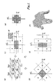
- Source luminance samples are split into two groups according to a grid with a 2 frame structure (see Fig. 1) which separates alternate samples with a line and frame offset.
- One group is to form an interpolated set, but in order to obtain a higher spatiotemporal resolution than fixed interpolation would permit, a 3-state interplator selection signal is retained at each site. Redundancy is removed from this selection signal and it is conveyed to the receiver.
- Values of this 3-state selector act as a descriptor at sites surrounding a sample to be predicted (the other group), and control selection of one of a set of 3 dimensional prediction functions, ranging from purely temporal in static areas to contour-adaptive in moving areas. Since the predictor choice is explicitly defined by the descriptors, recovery from channel errors is assured. Prediction error is quantised and coded for transmission.
- a third stage in the coding is used to check the quality of the interpolated samples reproduced at the receiver. This is done by locally decoding the transmitted signal at the coder and applying the error signal to a visual model in the manner of an interpolative coding process.
- the model attempts to locate interpolated samples which have not been reconstructed well enough subjectively, in the context of their surroundings. These are adjusted by the transmission of an error signal which is sufficient to ensure that the model's fidelity criterion is met at the receiver. As with most coders which attempt to exploit subjective criteria, the complexity bias is very much towards the encoder.
- Fig. 1(a) shows the structure of the set of samples to be predicted, for convenience nether the interlaced fields nor the true vertical sample spacing is shown.
- the interpolated set of samples resides between the samples shown. In static areas of the picture, full source resolution can be reconstructed by temporal interpolation.
- two frames are available at the source for movement detection, one before and one after that currently being coded.
- FIG. 1b shows that the 2 dimensional aliased spectra restrict the bandwidth which can be preserved using intrafield interpolation to areas which tessellate about the centres shown. Probably the best that can be obtained is the band shaded in the figure however pictures prefiltered to this extent are unacceptably degraded, so that the difference between static and moving resolution is disturbing.
- the bands in (c) and (d) which also tessellate about the alias centres each preserves half of the source bandwidth but together they can reproduce 3 ⁇ 4 of the source spectrum if switching is performed on a local basis.
- Cross-shaped prefilters can be conveniently designed from prototype horizontal and vertical lowpass filters in the following way:
- the additional "1" can be individually accounted for and the filter has an essentially separable structure, fig. 2. This is important, since practical filters are large, an excessive amount of hardware would be required to build a non-separable structure. For clarity fig. 2 does not show exploitation of filter symmetry this further simplifies the hardware. So that the filter is only applied in moving areas of the picture it is adapted in the manner mentioned in E. Dubds "The Sampling and Reconstruction of Time-Varying Imagery with Application in Video Systems" (Proc. IEEE, 73, 4, 502-522 1985).
- the adaption of the cross-filter is arranged so that for a picture or picture area of low movement, where ⁇ is low and temporal interpolation will apply, no cross-filtering is applied and as movement increases and ⁇ increases over a threshold, or series of thresholds, cross-filtering is applied to a greater extent, in a non-linear fashion, until for high ⁇ , where spatial switched horizontal and vertical filtering will apply, the cross-filter is fully operational.
- switched horizontal and vertical interplators are:
- the resulting 3-state signal is run-length coded for transmission.
- the value of the conversion from simple direct interpolator switching is now apparent in the ability of the Laplacian zero crossings to convey information about significant picture edges. It is interesting to note the similarly between this and Marr's "primal sketch" model in human vision (Marr and Hildreth "Theory of Edge Detection" Proc. R. Soc. Lond. B, 1980, 207, 187-217).
- the value of this new interpolator switching signal as a feature detector makes feasible an encoding system where temporal interpolation is dispensed with entirely. Any loss in picture quality is counterbalanced by the savings that would be made by dispensing with frame memories.
- An example of such an encoding system could use a 2-dimensional intrafield coder with 2-state logical descriptors for 68Mbit ⁇ s transmission of studio quality TV, or at a higher rate for HDTV transmission.
- the 3-state descriptor is transmitted to the decoder in advance of the surrounding predicted samples, this provides a sketch of the locality describing static areas and edges in moving areas. This description is now able to control the adaption of the predictive coding process - notice that descriptors are available for the future and the past. Let us examine the causal neighborhood of elements just prior to the coding of S00 : (P ij : previously predicted and reconstructed pels, D ij : values of the 3-state descriptor)
- the prediction function applied for a particular logical function is designed by assessing the covariance of the predicted sample location with previous samples in the neighbourhood where the logical function applies, over a set of image sequences.
- size of neighbourhood may be used and logical functions can be stored in a ROM or minimised and programmed into a PLA.
- Histograms of interpolation error even due to 2 dimensional interpolation alone, show a remarkably high concentration about zero despite the fact that an open-loop process has been employed so far. Most of the interpolation errors which are present occur where the localised samples are simultaneously changing their slope in two dimensions, because our interpolators cannot respond to second-differences. These will also tend to be regions where visual masking is operating.
- Visual models for detecting coding impairments generally account for three main aspects of vision: spatio-temporal filtering; luminance intensity thresholds; and masking.
- Fig. 6 shows such a model, where the visual filter may be considered to contain a non-linearity which accounts for changes in background luminance.
- a general model may well be unnecessarily complex to characterise the distortions due to a specific coding algorithm however.
- a first attempt at this was made by Limb (see above) whose visual model was a simple linear lowpass filter, an advantage of the linearity assumption being that the two filters of fig. 6 can be reduced to one, processing only the coding error.
- Limb proposed a "free-running" interpolative coding method, which although not real-time implementable, produced a saving in coding entropy of some 20% over previous-element DPCM for the same subjective quality. He does however report similar performance with his "grid” algorithm, where samples are alternately predictively coded and interpolated in one dimension. This latter approach overcomes some of the implementabiliy problems inherent in the former.
- Netravali A. netravali "Interpolative Picture Coding Using a Subjective Criterion", 1977 IEEE Trans. Comm., 25, 5, 503-508
- made significant improvements to the "free-running" approach by using better interpolation, by incorporating masking into the visual model and by adapting the visual filter spread with his masking function.
- a coding algorithm has been described for the transmission of distribution quality broadcast television at 34Mbit/s which can form the basis of an embedded code for providing a numerically higher fidelity at 68Mbit/s .
- the technique is a hybrid of interpolative and predictive coding both of which are explicitly controlled by a 3-state descriptor signal, transmitted in place of alternate source samples. This ensures a rapid recovery from the effects of channel errors.
- the channel capacity expended on this descriptor is justified by exploiting it in three ways, first it defines adaptive interpolation of the omitted samples, second it controls inter ⁇ intraframe-contour adaptive prediction and third it is used to control assignment of entropy codes to quantised errors which are used to adjust subjectively inadequate interpolated pels.
- An important aspect of the algorithm is that when channel capacity is insufficient to convey the highest quality reproduction, a model of the human visual system is used to partition available capacity for minimum subjective distortion.
- Any form of coding may be applied to the descriptor, predictive error, or interpolative error.
- An efficient form of transmitting the interpolation error is to interleave it with the prediction error.
- a spare state in the quantiser can be assigned to the signalling of this.
- Chrominance coding is performed by a decimation operation to a reduced density sample pattern and coded using either pure predictive and interpolative coding using the luminance descriptors to control the process.
- a diagram of the luminance coder implementing the preferred encoding algorithm is shown in fig. 7 (F denotes a frame delay).
- the decoder however is simpler than most adaptive DPCM decoders because of the explicit nature of the control function - this is important for distribution applications. Implementation is also eased because the predictive loop and frame delays are only operating on half of the input samples.
- This latter feature makes the encoding system according to the present invention particularly attractive as a method of encoding high definition television signals.
- the fill level of the output buffer is used to partly control the crossfilter adaption. This ensures that when a picture contains only small amounts of movement, full resolution can be retained in these areas.
- Emergency control to prevent rate-buffer overflow is also provided by changing the adaptive quantiser at coder and decoder to have a coarser structure. This too is controlled by the rate buffer fill-level.
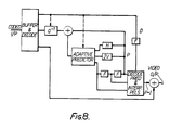
- FIG. 8 A diagram of a luminance decoder suitable for use with the preferred encoding algorithm is shown in fig. 8.
- This system permits retention of all source sampling sites (no decimation) and therefore allows a distribution quality signal to be embedded in a contribution quality signal at a higher rate and with higher numerical fidelity.
Landscapes
- Engineering & Computer Science (AREA)
- Multimedia (AREA)
- Signal Processing (AREA)
- Compression Or Coding Systems Of Tv Signals (AREA)
- Compression, Expansion, Code Conversion, And Decoders (AREA)
- Transmission Systems Not Characterized By The Medium Used For Transmission (AREA)
- Reduction Or Emphasis Of Bandwidth Of Signals (AREA)
Claims (23)
Einrichtungen zum Abtasten eines zu codierenden Fernsehsignals;
Einrichtungen zum Auswählen von Plätzen von zu interpolierenden Tastwerten durch eines aus mehreren Interpolationschemata;
Einrichtungen zum Verarbeiten von Tastwerten, die jedem zu interpolierenden Tastwert benachbart sind, um auszuwerten, welches der auf die benachbarten Tastwerte angewendete Interpolationsschema den besten Wert für den interpolierten Tastwert liefert;
Einrichtungen zum Erzeugen eines Beschreibersignals, das für jeden der räumlich zu interpolierenden Tastwerte geeignet ist, ein Beschreibersignal zu erzeugen, das angibt, ob das beste räumliche Interpolationsschema für diesen Tastwert einen Wert erzeugt, der gröber oder kleiner als der Mittelwert der Werte ist, die von der Vielzahl der räumlichen Interpolationsschemata erzeugt werden; und
Einrichtungen zum Übertragen der Beschreibersignale.

Eingabeeinrichtungen zum Aufnehmen eines codierten Fernsehsignals als einen Eingang, wobei das codierte Fernsehsignal mehrere Beschreibersignale enthält, jedes Beschreibersignal sich auf einen Tastwert des decodierten Fernsehsignals bezieht und für eines von mehreren Interpolationsschemata kennzeichnend ist, die auf dem Tastwert benachbarte Tastwerte anzuwenden sind, um den Tastwert im wesentlichen zu rekonstruieren, wobei wenigstens einige der Beschreibersignale für einige der räumlichen Interpolationsschemata kennzeichend sind, die wenigstens einigen Beschreibersignale jeweils angeben, ob der Wert für den entsprechenden Tastwert nach der Rekonstruktion unter Verwendung des entsprechenden räumlichen Interpolationsschemas höher oder niedriger als der Mittelwert der von den räumlichen Interpolationsschemata erzeugten Werten ist;
Extraktionseinrichtungen, die mit den Eingabeeinrichtungen verbunden sind, um die Beschreibersignale aus den codierten Fernsehsignalen abzuleiten;
Interpolationseinrichtungen, die mit den Extraktionseinrichtungen verbunden sind, um jeden der Tastwerte des decodierten Fernsehsignals zu rekonstruieren, in dem das Interpolationsschema, das durch das durch das relevante Beschreibersignal angegeben wird, auf Signale angewendet wird, die die rekonstruierten Nachbarsignale repräsentieren; und
Ausgabeeinrichtungen, die mit den Interpolationseinrichtungen verbunden sind, um die rekonstruierten Tastwerte auszugeben.
die Extraktionseinrichtungen dazu eingerichtet sind, die Vorhersagefehlersignale aus dem codierten Fernsehsignal abzuleiten; weiterhin ein adaptiver Vorhersager vorgesehen ist, der mit den Extraktionseinrichtungen verbunden ist, um jeden Tastwert, auf den sich die Vorhersagefehlersignale beziehen, zu rekonstruieren, indem eines der Vorhersageschemata auf die relevanten rekonstruierten Nachbartastwerte angewendet wird und das Ergebnis durch einen Betrag eingestellt wird, der durch den Wert des relevanten Vorhersagefehlersignals bestimmt wird;
der adaptive Vorhersager dazu eingerichtet ist, jeden Tastwert unter Verwendung eines Vorhersageschemas zu rekonstruieren, das durch die Werte der Vorhersagersignale bestimmt wird, die sich auf die Nachbartastwerte beziehen;
die Interpolationseinrichtungen mit dem adaptiven Vorhersager verbunden sind und dazu eingerichtet sind, die Interpolationschemata auf Signale anzuwenden, die Tastwerte repräsentieren, die von dem adaptiven Vorhersager rekonstruiert werden, und auf Tastwerte, die durch die Interpolationseinrichtungen selbst rekonstruiert werden; und
die Ausgabeeinrichtungen dazu eingerichtet sind, Tastwerte auszugeben, die durch die Interpolationseinrichtungen und den adaptiven Vorhersager rekonstruiert worden sind.
Abtasten eines zu codierenden Fernsehsignals;
Auswählen von zu interpolierenden Plätzen durch eines aus mehreren Interpolationsschemata, wobei die Interpolationsschemata mehrere räumliche Interpolationsschemata enthalten;
für jeden zu interpolierenden Tastwert Verarbeiten von dem zu interpolierenden Tastwert benachbarten Tastwerten, um zu ermitteln, welches an den Nachbartastwerten angewendete Interpolationsschema den besten Wert für diesen interpolierten Tastwert erzeugt;
für jeden räumlich zu interpolierenden Tastwert das Erzeugen eines Beschreibersignals, das angibt, ob das beste räumliche Interpolationsschema für diesen interpolierten Tastwert einen Wert erzeugt, der höher oder niedriger als der Mittelwert der Werte ist, die von den räumlichen Interpolationsschemata erzeugt werden; und
Einrichtungen zum Übertragen der Beschreibersignale.
Priority Applications (1)
| Application Number | Priority Date | Filing Date | Title |
|---|---|---|---|
| AT87901536T ATE68305T1 (de) | 1986-02-17 | 1987-02-17 | Vorrichtung zum kodieren eines zu uebertragenden fernsehsignals. |
Applications Claiming Priority (2)
| Application Number | Priority Date | Filing Date | Title |
|---|---|---|---|
| GB868603880A GB8603880D0 (en) | 1986-02-17 | 1986-02-17 | Hybrid interpolative predictive code |
| GB8603880 | 1986-02-17 |
Publications (2)
| Publication Number | Publication Date |
|---|---|
| EP0258367A1 EP0258367A1 (de) | 1988-03-09 |
| EP0258367B1 true EP0258367B1 (de) | 1991-10-09 |
Family
ID=10593189
Family Applications (1)
| Application Number | Title | Priority Date | Filing Date |
|---|---|---|---|
| EP87901536A Expired EP0258367B1 (de) | 1986-02-17 | 1987-02-17 | Vorrichtung zum kodieren eines zu übertragenden fernsehsignals |
Country Status (7)
| Country | Link |
|---|---|
| US (1) | US4858005A (de) |
| EP (1) | EP0258367B1 (de) |
| JP (1) | JP2542025B2 (de) |
| AT (1) | ATE68305T1 (de) |
| DE (1) | DE3773591D1 (de) |
| GB (1) | GB8603880D0 (de) |
| WO (1) | WO1987005179A1 (de) |
Families Citing this family (17)
| Publication number | Priority date | Publication date | Assignee | Title |
|---|---|---|---|---|
| JPS63215185A (ja) * | 1987-03-03 | 1988-09-07 | Matsushita Electric Ind Co Ltd | サブナイキスト符号化装置および復号化装置 |
| NL8803152A (nl) * | 1988-12-23 | 1990-07-16 | Philips Nv | Prediktieve kodeer- en dekodeerschakeling voor beeldelementwaarden. |
| GB9022326D0 (en) * | 1990-10-15 | 1990-11-28 | British Telecomm | Signal coding |
| US5122875A (en) * | 1991-02-27 | 1992-06-16 | General Electric Company | An HDTV compression system |
| US5111292A (en) * | 1991-02-27 | 1992-05-05 | General Electric Company | Priority selection apparatus as for a video signal processor |
| JP3093499B2 (ja) * | 1992-03-06 | 2000-10-03 | 三菱電機株式会社 | シーンチェンジ検出装置 |
| US8821276B2 (en) * | 1992-05-22 | 2014-09-02 | Bassilic Technologies Llc | Image integration, mapping and linking system and methodology |
| US5553864A (en) | 1992-05-22 | 1996-09-10 | Sitrick; David H. | User image integration into audiovisual presentation system and methodology |
| KR0166727B1 (ko) * | 1992-11-27 | 1999-03-20 | 김광호 | 영상움직임관련정보를 양자화제어에 이용하는 부호화방법 및 장치 |
| JPH06311496A (ja) * | 1993-04-26 | 1994-11-04 | Sony Corp | 画像信号伝送方法及び画像信号伝送装置 |
| DE69615812T2 (de) * | 1995-08-02 | 2002-06-20 | Koninklijke Philips Electronics N.V., Eindhoven | Verfahren und system zur kodierung einer bildsequenz |
| KR100235064B1 (ko) * | 1996-05-23 | 1999-12-15 | 전주범 | 재배열된 블록 기반 부호화 기법을 이용하여 비디오 신호의 물체영역을 부호화하기 위한 장치 |
| JPH1169356A (ja) * | 1997-08-25 | 1999-03-09 | Mitsubishi Electric Corp | 動画像符号化方式及び動画像復号方式 |
| EP1199895B1 (de) | 2000-10-20 | 2005-09-14 | Samsung Electronics Co., Ltd. | Kodierer, Dekodierer und entsprechende Verfahren für Orientierungsinterpolationsknotendaten |
| JP2003060886A (ja) * | 2001-08-09 | 2003-02-28 | Matsushita Electric Ind Co Ltd | 画像処理装置及び方法 |
| US7437194B2 (en) * | 2003-10-31 | 2008-10-14 | Medtronic, Inc. | Stimulating the prostate gland |
| US20120189064A1 (en) * | 2011-01-14 | 2012-07-26 | Ebrisk Video Inc. | Adaptive loop filtering using multiple filter shapes |
Family Cites Families (9)
| Publication number | Priority date | Publication date | Assignee | Title |
|---|---|---|---|---|
| US3715483A (en) * | 1970-12-11 | 1973-02-06 | Bell Telephone Labor Inc | Bandwidth reduction system for use with video signals |
| FR2489061A1 (fr) * | 1980-08-20 | 1982-02-26 | France Etat | Systeme de transmission d'images utilisant un dispositif de restitutions de points |
| US4383272A (en) * | 1981-04-13 | 1983-05-10 | Bell Telephone Laboratories, Incorporated | Video signal interpolation using motion estimation |
| JPS58127488A (ja) * | 1982-01-25 | 1983-07-29 | Kokusai Denshin Denwa Co Ltd <Kdd> | テレビジヨン信号の適応予測符号化方式 |
| EP0113514B1 (de) * | 1982-11-30 | 1988-05-11 | BRITISH TELECOMMUNICATIONS public limited company | Übertragung eines Fernsehsignals |
| US4605963A (en) * | 1983-08-15 | 1986-08-12 | Rca Corporation | Reduction of control bits for adaptive sub-nyquist encoder |
| DE3586512T2 (de) * | 1984-05-29 | 1993-03-11 | Gen Electric | Raumzeitliche signalverarbeitung mit frequenzverkammung eines fernsehsignals. |
| US4703350A (en) * | 1985-06-03 | 1987-10-27 | Picturetel Corporation | Method and apparatus for efficiently communicating image sequences |
| US4665436A (en) * | 1985-12-20 | 1987-05-12 | Osborne Joseph A | Narrow bandwidth signal transmission |
-
1986
- 1986-02-17 GB GB868603880A patent/GB8603880D0/en active Pending
-
1987
- 1987-02-17 EP EP87901536A patent/EP0258367B1/de not_active Expired
- 1987-02-17 DE DE8787901536T patent/DE3773591D1/de not_active Expired - Fee Related
- 1987-02-17 WO PCT/GB1987/000116 patent/WO1987005179A1/en not_active Ceased
- 1987-02-17 JP JP62501247A patent/JP2542025B2/ja not_active Expired - Lifetime
- 1987-02-17 AT AT87901536T patent/ATE68305T1/de not_active IP Right Cessation
- 1987-10-14 US US07/113,822 patent/US4858005A/en not_active Expired - Lifetime
Also Published As
| Publication number | Publication date |
|---|---|
| JP2542025B2 (ja) | 1996-10-09 |
| US4858005A (en) | 1989-08-15 |
| JPS63502713A (ja) | 1988-10-06 |
| EP0258367A1 (de) | 1988-03-09 |
| GB8603880D0 (en) | 1986-03-26 |
| DE3773591D1 (de) | 1991-11-14 |
| ATE68305T1 (de) | 1991-10-15 |
| WO1987005179A1 (en) | 1987-08-27 |
Similar Documents
| Publication | Publication Date | Title |
|---|---|---|
| EP0258367B1 (de) | Vorrichtung zum kodieren eines zu übertragenden fernsehsignals | |
| EP0451545B1 (de) | Gerät und Verfahren zur adaptiven Kompression von aufeinanderfolgenden Blöcken eines digitalen Videosignals | |
| KR950005665B1 (ko) | 고능률 부호화 장치 | |
| US4665436A (en) | Narrow bandwidth signal transmission | |
| US5543939A (en) | Video telephone systems | |
| KR100255718B1 (ko) | 비디오 신호처리기용 우선도 선택장치 | |
| EP0467040B1 (de) | Adaptive Bewegungskompensation für das digitale Fernsehen | |
| JP4240554B2 (ja) | 画像符号化装置および画像符号化方法、並びに画像復号化装置および画像復号化方法 | |
| Limb et al. | An interframe coding technique for broadcast television | |
| HK1008410B (en) | Apparatus and method for adaptively compressing successive blocks of digital video | |
| JPS61114675A (ja) | フレ−ム間符工化方式におけるリフレツシユ処理方式 | |
| US4488175A (en) | DPCM Video signal processing technique with spatial subsampling | |
| Paik | DigiCipher-all digital, channel compatible, HDTV broadcast system | |
| US5068726A (en) | Coding apparatus that temporally interpolates block data and selects transmission mode | |
| Challapali et al. | The grand alliance system for US HDTV | |
| WO1991010328A1 (en) | Video telephone systems | |
| US5652624A (en) | Systems for dither-quantizing and reconstruction of digital television signals | |
| Bauch et al. | Picture coding | |
| WO1987004032A1 (en) | Method of transmitting a video signal in sampled form | |
| Netravali | Image Processing for Communication | |
| Netravali et al. | Examples of Codec Designs | |
| Troxel | Application of pseudorandom noise to DPCM | |
| Crinon | Picture compression based on two-dimensional adaptive sampling and adaptive quantization | |
| Musmann | Digital coding of television signals | |
| Meeker | High definition and high frame rate compatible NTSC broadcast television system |
Legal Events
| Date | Code | Title | Description |
|---|---|---|---|
| PUAI | Public reference made under article 153(3) epc to a published international application that has entered the european phase |
Free format text: ORIGINAL CODE: 0009012 |
|
| 17P | Request for examination filed |
Effective date: 19871022 |
|
| AK | Designated contracting states |
Kind code of ref document: A1 Designated state(s): AT BE CH DE FR GB IT LI LU NL SE |
|
| 17Q | First examination report despatched |
Effective date: 19900406 |
|
| 17Q | First examination report despatched |
Effective date: 19900912 |
|
| RAP1 | Party data changed (applicant data changed or rights of an application transferred) |
Owner name: NATIONAL TRANSCOMMUNICATIONS LIMITED |
|
| GRAA | (expected) grant |
Free format text: ORIGINAL CODE: 0009210 |
|
| AK | Designated contracting states |
Kind code of ref document: B1 Designated state(s): AT BE CH DE FR GB IT LI LU NL SE |
|
| PG25 | Lapsed in a contracting state [announced via postgrant information from national office to epo] |
Ref country code: SE Effective date: 19911009 Ref country code: AT Effective date: 19911009 |
|
| REF | Corresponds to: |
Ref document number: 68305 Country of ref document: AT Date of ref document: 19911015 Kind code of ref document: T |
|
| ITF | It: translation for a ep patent filed | ||
| REF | Corresponds to: |
Ref document number: 3773591 Country of ref document: DE Date of ref document: 19911114 |
|
| ET | Fr: translation filed | ||
| PLBE | No opposition filed within time limit |
Free format text: ORIGINAL CODE: 0009261 |
|
| STAA | Information on the status of an ep patent application or granted ep patent |
Free format text: STATUS: NO OPPOSITION FILED WITHIN TIME LIMIT |
|
| 26N | No opposition filed | ||
| EPTA | Lu: last paid annual fee | ||
| REG | Reference to a national code |
Ref country code: GB Ref legal event code: 732E |
|
| REG | Reference to a national code |
Ref country code: GB Ref legal event code: 732E |
|
| REG | Reference to a national code |
Ref country code: GB Ref legal event code: IF02 |
|
| PGFP | Annual fee paid to national office [announced via postgrant information from national office to epo] |
Ref country code: LU Payment date: 20021230 Year of fee payment: 17 |
|
| PGFP | Annual fee paid to national office [announced via postgrant information from national office to epo] |
Ref country code: GB Payment date: 20030106 Year of fee payment: 17 |
|
| PGFP | Annual fee paid to national office [announced via postgrant information from national office to epo] |
Ref country code: NL Payment date: 20030110 Year of fee payment: 17 |
|
| PGFP | Annual fee paid to national office [announced via postgrant information from national office to epo] |
Ref country code: FR Payment date: 20030204 Year of fee payment: 17 |
|
| PGFP | Annual fee paid to national office [announced via postgrant information from national office to epo] |
Ref country code: DE Payment date: 20030228 Year of fee payment: 17 |
|
| PGFP | Annual fee paid to national office [announced via postgrant information from national office to epo] |
Ref country code: BE Payment date: 20030312 Year of fee payment: 17 |
|
| PGFP | Annual fee paid to national office [announced via postgrant information from national office to epo] |
Ref country code: CH Payment date: 20030319 Year of fee payment: 17 |
|
| PG25 | Lapsed in a contracting state [announced via postgrant information from national office to epo] |
Ref country code: LU Free format text: LAPSE BECAUSE OF NON-PAYMENT OF DUE FEES Effective date: 20040217 Ref country code: GB Free format text: LAPSE BECAUSE OF NON-PAYMENT OF DUE FEES Effective date: 20040217 |
|
| PG25 | Lapsed in a contracting state [announced via postgrant information from national office to epo] |
Ref country code: BE Free format text: LAPSE BECAUSE OF NON-PAYMENT OF DUE FEES Effective date: 20040228 |
|
| PG25 | Lapsed in a contracting state [announced via postgrant information from national office to epo] |
Ref country code: LI Free format text: LAPSE BECAUSE OF NON-PAYMENT OF DUE FEES Effective date: 20040229 Ref country code: CH Free format text: LAPSE BECAUSE OF NON-PAYMENT OF DUE FEES Effective date: 20040229 |
|
| BERE | Be: lapsed |
Owner name: *NATIONAL TRANSCOMMUNICATIONS LTD Effective date: 20040228 |
|
| PG25 | Lapsed in a contracting state [announced via postgrant information from national office to epo] |
Ref country code: NL Free format text: LAPSE BECAUSE OF NON-PAYMENT OF DUE FEES Effective date: 20040901 Ref country code: DE Free format text: LAPSE BECAUSE OF NON-PAYMENT OF DUE FEES Effective date: 20040901 |
|
| GBPC | Gb: european patent ceased through non-payment of renewal fee |
Effective date: 20040217 |
|
| REG | Reference to a national code |
Ref country code: CH Ref legal event code: PL |
|
| PG25 | Lapsed in a contracting state [announced via postgrant information from national office to epo] |
Ref country code: FR Free format text: LAPSE BECAUSE OF NON-PAYMENT OF DUE FEES Effective date: 20041029 |
|
| NLV4 | Nl: lapsed or anulled due to non-payment of the annual fee |
Effective date: 20040901 |
|
| REG | Reference to a national code |
Ref country code: FR Ref legal event code: ST |
|
| PG25 | Lapsed in a contracting state [announced via postgrant information from national office to epo] |
Ref country code: IT Free format text: LAPSE BECAUSE OF NON-PAYMENT OF DUE FEES;WARNING: LAPSES OF ITALIAN PATENTS WITH EFFECTIVE DATE BEFORE 2007 MAY HAVE OCCURRED AT ANY TIME BEFORE 2007. THE CORRECT EFFECTIVE DATE MAY BE DIFFERENT FROM THE ONE RECORDED. Effective date: 20050217 |