EP0257659B1 - Vorrichtung zum Formen einer Schattenmaske - Google Patents
Vorrichtung zum Formen einer Schattenmaske Download PDFInfo
- Publication number
- EP0257659B1 EP0257659B1 EP87112589A EP87112589A EP0257659B1 EP 0257659 B1 EP0257659 B1 EP 0257659B1 EP 87112589 A EP87112589 A EP 87112589A EP 87112589 A EP87112589 A EP 87112589A EP 0257659 B1 EP0257659 B1 EP 0257659B1
- Authority
- EP
- European Patent Office
- Prior art keywords
- die
- contour
- mask blank
- mask
- punch
- Prior art date
- Legal status (The legal status is an assumption and is not a legal conclusion. Google has not performed a legal analysis and makes no representation as to the accuracy of the status listed.)
- Expired - Lifetime
Links
- 230000000295 complement effect Effects 0.000 claims description 11
- 230000002093 peripheral effect Effects 0.000 claims description 9
- 238000000034 method Methods 0.000 description 5
- OAICVXFJPJFONN-UHFFFAOYSA-N Phosphorus Chemical compound [P] OAICVXFJPJFONN-UHFFFAOYSA-N 0.000 description 3
- 230000013011 mating Effects 0.000 description 2
- 230000037303 wrinkles Effects 0.000 description 2
- 239000004593 Epoxy Substances 0.000 description 1
- 229910000831 Steel Inorganic materials 0.000 description 1
- 230000015556 catabolic process Effects 0.000 description 1
- 239000003086 colorant Substances 0.000 description 1
- 238000006731 degradation reaction Methods 0.000 description 1
- 238000010894 electron beam technology Methods 0.000 description 1
- 238000004519 manufacturing process Methods 0.000 description 1
- 239000010959 steel Substances 0.000 description 1
- 239000010409 thin film Substances 0.000 description 1
Images

Classifications
-
- H—ELECTRICITY
- H01—ELECTRIC ELEMENTS
- H01J—ELECTRIC DISCHARGE TUBES OR DISCHARGE LAMPS
- H01J9/00—Apparatus or processes specially adapted for the manufacture, installation, removal, maintenance of electric discharge tubes, discharge lamps, or parts thereof; Recovery of material from discharge tubes or lamps
-
- B—PERFORMING OPERATIONS; TRANSPORTING
- B21—MECHANICAL METAL-WORKING WITHOUT ESSENTIALLY REMOVING MATERIAL; PUNCHING METAL
- B21D—WORKING OR PROCESSING OF SHEET METAL OR METAL TUBES, RODS OR PROFILES WITHOUT ESSENTIALLY REMOVING MATERIAL; PUNCHING METAL
- B21D22/00—Shaping without cutting, by stamping, spinning, or deep-drawing
- B21D22/02—Stamping using rigid devices or tools
-
- H—ELECTRICITY
- H01—ELECTRIC ELEMENTS
- H01J—ELECTRIC DISCHARGE TUBES OR DISCHARGE LAMPS
- H01J9/00—Apparatus or processes specially adapted for the manufacture, installation, removal, maintenance of electric discharge tubes, discharge lamps, or parts thereof; Recovery of material from discharge tubes or lamps
- H01J9/02—Manufacture of electrodes or electrode systems
- H01J9/14—Manufacture of electrodes or electrode systems of non-emitting electrodes
- H01J9/142—Manufacture of electrodes or electrode systems of non-emitting electrodes of shadow-masks for colour television tubes
-
- G—PHYSICS
- G03—PHOTOGRAPHY; CINEMATOGRAPHY; ANALOGOUS TECHNIQUES USING WAVES OTHER THAN OPTICAL WAVES; ELECTROGRAPHY; HOLOGRAPHY
- G03G—ELECTROGRAPHY; ELECTROPHOTOGRAPHY; MAGNETOGRAPHY
- G03G2215/00—Apparatus for electrophotographic processes
- G03G2215/20—Details of the fixing device or porcess
- G03G2215/2003—Structural features of the fixing device
- G03G2215/2016—Heating belt
- G03G2215/2025—Heating belt the fixing nip having a rotating belt support member opposing a pressure member
- G03G2215/2029—Heating belt the fixing nip having a rotating belt support member opposing a pressure member the belt further entrained around one or more stationary belt support members, the latter not being a cooling device
-
- G—PHYSICS
- G03—PHOTOGRAPHY; CINEMATOGRAPHY; ANALOGOUS TECHNIQUES USING WAVES OTHER THAN OPTICAL WAVES; ELECTROGRAPHY; HOLOGRAPHY
- G03G—ELECTROGRAPHY; ELECTROPHOTOGRAPHY; MAGNETOGRAPHY
- G03G2215/00—Apparatus for electrophotographic processes
- G03G2215/20—Details of the fixing device or porcess
- G03G2215/2003—Structural features of the fixing device
- G03G2215/2016—Heating belt
- G03G2215/2025—Heating belt the fixing nip having a rotating belt support member opposing a pressure member
- G03G2215/2032—Heating belt the fixing nip having a rotating belt support member opposing a pressure member the belt further entrained around additional rotating belt support members
Definitions
- This invention pertains to an apparatus for forming a shadow mask for a color cathode-ray tube from a mask blank, including a punch, a pad, and upper and lower dies for clamping the mask blank.
- a color cathode-ray tube employs three electron guns for emitting three electron beams which pass through a common deflection yoke, with one beam for each of the primary phosphor colors, i.e., red, green and blue.
- the beams are "shadowed" by a perforated conductive mask, known as a shadow mask, so that each beam can strike but one color of a segmented cathodoluminescent screen of red, green and blue phosphors disposed close to the mask on the inside surface of a faceplate panel.
- a perforated conductive mask known as a shadow mask
- a conventional spherical-like shadow mask is formed from a flat mask blank by first clamping the blank around its periphery between upper and lower dies having openings therein for receiving a punch having a convex surface and a pad having a complementary concave surface.
- the punch and the pad are shaped with a spherical-like surface contour that provides the desired mask contour, i.e., allowance is made for springback after forming.
- the clamping surfaces of the upper and lower dies, adjacent the respective openings typically have a nonplanar surface contour which is a continuation of the spherical-like surface contour of the punch surface. Consequently, when the mask blank is laid onto the lower die surface, the surface contour assumed by the blank does not match the surface contour of the die, resulting in a wrinkling of the blank as it is clamped between the upper and lower dies.
- EP-A3-0 165 785 discloses a similar method, in which dies with cylindrical planar clamping surfaces are used.
- the wrinkles in the clamped mask blank must be stretched out to achieve a smooth surface contour.
- the initial portions of the mask skirt are formed while the mask blank is still clamped between the upper and lower dies, thereby stretching out the periphery of the mask to provide a smoother contour.
- the mask apertures in the wrinkled areas stretch differently than those apertures not in wrinkled areas. This causes nonuniform stretching in the mask and, since the wrinkles are different from mask to mask, the stretching is different from mask to mask.
- Such nonuniform stretching of the shadow mask ultimately results in a lowering of color purity in larger size cathode-ray tubes and in high-resolution display tubes. It is desirable to have an apparatus for forming a shadow mask which avoids such a degradation in color purity.
- the present invention comprises an apparatus for forming a shadow mask from a mask blank, including a punch having a convex surface, a pad having a complementary concave surface, and upper and lower dies having openings therein for receiving the punch and the pad, respectively.
- Each die also has a complementary nonplanar surface with inner edges adjacent the opening for clamping the mask blank.
- Each die surface has a surface contour that substantially matches the extended surface contour of the mask blank when the mask blank ⁇ is pushed ⁇ unclamped against the inner edges of the lower die surface, so that wrinkling does not occur when the mask blank is clamped between the upper and lower dies.
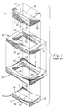
- FIGURE 1 shows a prior apparatus for forming a shadow mask, which includes a punch 10 having a convex bottom surface 12, a pad 14 having a complementary concave top surface 16, and upper and lower dies 18 and 20 having central rectangular-shaped openings 22 and 24 therein for receiving the punch 10 and the pad 14, respectively.
- the punch 10, pad 14, and upper and lower dies 18 and 20 preferably are made of steel.
- the lower die 20 has a nonplanar top surface 26 adjacent the opening 24 for supporting a mask blank (not shown), and the upper die 18 has a nonplanar bottom surface 28 adjacent the opening 22 which is complementary to the surface 26, for mating with the lower die 20 and clamping the mask blank during the mask-forming operation.
- the press can be a 200 ton model manufactured by BH Press Corporation, Philadelphia, PA.
- the convex surface 12 of the punch 10 is curved in three dimensions, as indicated by curved dotted lines 30 and 32 lying along intersecting orthogonal planes, respectively. Since the openings 22 and 24 are rectangular in shape, the convex surface 12 has two opposing peripheral edges 34 and 36 which are curved in the same planar direction as the dotted line 30, and two opposing peripheral edges 38 and 40 which are curved in the same planar direction as the dotted line 32.
- the concave top surface 16 of the pad 14 also is curved in three dimensions, as indicated by curved dotted lines 42 and 44 lying along intersecting orthogonal planes, respectively.
- the concave surface 16 has two opposing peripheral edges 46 and 48 which are curved in the same planar direction as the dotted line 42, and two opposing peripheral edges 50 and 52 which are curved in the same planar direction as the dotted line 44.
- the curvature of the dotted lines 42 and 44 and the peripheral edges 46, 48, 50 and 52 matches that of the dotted lines 30 and 32 and the peripheral edges 34, 36, 38 and 40, respectively, of the bottom surface 12 of the punch 10.
- the punch 10 and the pad 14 can be placed together without any space therebetween (assuming that a mask blank is not present).
- the bottom surface 28 of the upper die 18 is convexly curved in three dimensions and has four curved inner edges 54, 56, 58 and 60 which define the opening 22.
- the top surface 26 of the lower die 20 is concavely curved in three dimensions with a surface contour which matches that of the bottom surface 28 of the upper die 18.
- the top surface 26 of the lower die 20 has four curved inner edges 62, 64, 66 and 68 which define the opening 24.
- the inner edges 54-60 and 62-68 of the bottom and top die surfaces 28 and 26 match the contour of the peripheral edges 34-40, respectively, of the punch surface 12.
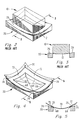
- FIGURES 2 and 3 show the punch 10 and the lower die 20 adjacent to each other.
- the concave top surface 26 of the lower die 20 has a surface contour which is a continuation of the convex bottom surface 12 of the punch 10, as illustrated in FIGURE 3. Consequently, when a flat mask blank is laid onto the lower die surface 26, the surface contour assumed by the blank does not match the surface contour of the die 20, resulting in a wrinkling of the blank as it is clamped between the upper and lower dies 18 and 20.
- FIGURES 4 and 5 illustrate the present inventive concept.
- An unclamped mask blank 70 is pushed down to contact and lie against the inner edges 62, 64, 66 and 68 of the lower die 20.
- the inner edges 62, 64, 66 and 68 of the lower die 20 support the mask blank 70 and cause it to assume an unwrinkled surface contour different from the top surface 26 of the lower die 20, as shown in FIGURE 5.
- the present invention provides for a die surface 72 which has a surface contour that substantially matches the extended surface contour of the unwrinkled mask blank 70 as it lies against the inner edges 62, 64, 66 and 68 of the lower die 20.
- the mask blank 70 is supported by a "built-up" section, shown by dotted line 74, which is disposed adjacent the surface 26 of the prior die 20.
- the surface 72 of this built-up section 74 has a concave spherical-like contour which is different from that of the surface 26 in that the corners of this surface 72 are bent upward, as shown in FIGURE 4.
- the upper die 18 would have a surface complementary to the lower die surface 72.
- the surface contour of the lower die surface 72 comprises a complex surface, which may be mathematically defined if desired.
- one technique is to support the mask blank 70 on the inner edges 62, 64, 66 and 68 and build a rigid structure on top of the blank 70 which conforms to the contour of this surface 72.
- Such a structure may be created by an epoxy build-up process wherein thin films are first deposited adjacent to the surface 72, followed by thicker support layers. This rigid structure is then used as a mold for defining the surface contour of the upper and lower dies.
- FIGURE 6 shows one embodiment of an apparatus 76 incorporating the present invention.
- the apparatus 76 comprises a punch 78 having a convex bottom surface 80, a pad 82 having a complementary concave top surface 84, and upper and lower dies 86 and 88 having central, substantially rectangular-shaped openings 90 and 92 therein for receiving the punch 78 and the pad 82, respectively.
- Both the bottom surface 80 and the top surface 84 of the punch 78 and pad 82 have spherical-like surface contours.
- the lower die 88 has a continuous cylindrical surface 94 adjacent the opening 92 for supporting a mask blank (not shown), and the upper die 86 has a continuous cylindrical surface 96 adjacent the opening 90, which is complementary to the surface 94, for mating with the lower die 88 and clamping the mask blank during the mask-forming operation.
- the minor axis of each opening 90 and 92 is oriented parallel to the axis of the cylindrical surfaces 94 and 96.
- the cylindrical surface 94 of the lower die 88 has four curved inner edges 98, 100, 102 and 104 which define the opening 92
- the cylindrical surface 96 of the upper die 86 has four curved inner edges 106, 108, 110 and 112 which define the opening 90.
- the inner edges 98-104 and 106-112 of the cylindrical surfaces 94 and 96, respectively, substantially match the contour of the corresponding peripheral edges 114, 116, 118 and 120 of the punch surface 80.
- the cylindrical surface 94 allows an unclamped mask blank to lie against and conform to the contour of the lower die surface 94, so that wrinkling of the mask blank does not occur when the blank is clamped between the lower and upper die surfaces 94 and 96.
- a stretching-out process on the shadow mask which may result in a lowering of color purity in larger size cathode-ray tubes and in high-resolution display tubes.
Landscapes
- Engineering & Computer Science (AREA)
- Manufacturing & Machinery (AREA)
- Mechanical Engineering (AREA)
- Shaping Metal By Deep-Drawing, Or The Like (AREA)
- Respiratory Apparatuses And Protective Means (AREA)
Claims (6)
- Vorrichtung zum Formen einer Schattenmaske aus einem Maskenrohling (70), mit einer Patrize (78), die eine konvexe Oberfläche (80) hat, einer Matrize (82), die eine komplementäre konkave Oberfläche hat, sowie einem oberen und einem unteren Gesenk (86, 88), die Öffnungen (90, 92) zur Aufnahme der Patrize bzw. Matrize haben und jeweils eine komplementäre nicht-ebene Oberfläche (94, 96) mit inneren Rändern bei der Öffnung zum Festklemmen des Maskenrohlings aufweisen, dadurch gekennzeichnet, daß die Gesenkoberflächen (96, 94) jeweils eine Oberflächenkontur aufweisen, welche im wesentlichen mit der verlängerten Oberflächenkontur des Maskenrohlings (70) übereinstimmt, wenn dieser ohne eingeklemmt zu werden gegen die inneren Ränder (98-104) der unteren Gesenkfläche (94) gedrückt wird, so daß keine Falten entstehen, wenn der Maskenrohling zwischen das obere (86) und das untere (88) Gesenk eingeklemmt wird.
- Vorrichtung nach Anspruch 1, dadurch gekennzeichnet, daß die Flächenkontur der Oberfläche des unteren Gesenks (94) eine konkave, kugelflächenartige Fläche enthält und daß die Flächenkontur der Oberfläche (96) des oberen Gesenks eine konvexe kugelflächenartige Oberfläche enthält.
- Vorrichtung nach Anspruch 1, dadurch gekennzeichnet, daß die Oberflächenkontur jedes Gesenks (86, 88) eine kontinuierliche zylindrische Fläche (96, 94) enthält.
- Vorrichtung nach Anspruch 3, dadurch gekennzeichnet, daß die Öffnungen (90, 92) in den Gesenken (86, 88) jeweils im wesentlichen die Form eines Rechtecks aufweisen, dessen kleine Achse parallel zur Achse der genannten zylindrischen Fläche (96, 94) verläuft.
- Vorrichtung nach Anspruch 4, dadurch gekennzeichnet, daß die gegenüberliegenden Innenränder (106, 110, 98, 102) der Gesenkoberflächen (96, 94), die längs der kürzeren Seiten der jeweiligen Gesenköffnung (90, 92) verlaufen, eine gebogene Form haben.
- Vorrichtung nach Anspruch 5, dadurch gekennzeichnet, daß die inneren Ränder (102-112, 98-104) der Gesenkoberflächen (96, 94) jeweils im wesentlichen mit der Kontur der Umfangsränder (114-120) der Patrizenoberfläche (80) übereinstimmen.
Applications Claiming Priority (2)
| Application Number | Priority Date | Filing Date | Title |
|---|---|---|---|
| US06/901,569 US4719787A (en) | 1986-08-29 | 1986-08-29 | Apparatus for forming a shadow mask |
| US901569 | 1986-08-29 |
Publications (3)
| Publication Number | Publication Date |
|---|---|
| EP0257659A2 EP0257659A2 (de) | 1988-03-02 |
| EP0257659A3 EP0257659A3 (en) | 1989-03-08 |
| EP0257659B1 true EP0257659B1 (de) | 1993-05-05 |
Family
ID=25414439
Family Applications (1)
| Application Number | Title | Priority Date | Filing Date |
|---|---|---|---|
| EP87112589A Expired - Lifetime EP0257659B1 (de) | 1986-08-29 | 1987-08-28 | Vorrichtung zum Formen einer Schattenmaske |
Country Status (6)
| Country | Link |
|---|---|
| US (1) | US4719787A (de) |
| EP (1) | EP0257659B1 (de) |
| JP (1) | JPS6364238A (de) |
| KR (1) | KR950006090B1 (de) |
| CA (1) | CA1273395A (de) |
| DE (1) | DE3785705T2 (de) |
Families Citing this family (6)
| Publication number | Priority date | Publication date | Assignee | Title |
|---|---|---|---|---|
| IT1239511B (it) * | 1990-03-30 | 1993-11-03 | Videocolor Spa | Metodo di formatura di una maschera d'ombra per un tubo di riproduzione di immagini a colori |
| DE4227652C2 (de) * | 1992-08-21 | 1996-02-29 | Daimler Benz Ag | Verfahren und Einrichtung zum Einlegen von Platinen in Ziehwerkzeuge |
| DE20122801U1 (de) * | 2000-05-11 | 2008-10-02 | Autoform Engineering Gmbh | Computerlesbares Medium mit Programm zur Erzeugung von Ankonstruktionen von Werkzeugen für Blechformteile |
| WO2007131019A2 (en) * | 2006-05-04 | 2007-11-15 | Ethicon, Inc. | Tissue holding devices and methods for making the same |
| JP4386130B2 (ja) * | 2007-11-30 | 2009-12-16 | トヨタ自動車株式会社 | プレス装置用金型および開放絞り成形方法 |
| US20130193172A1 (en) * | 2012-01-27 | 2013-08-01 | Michael J. Damkot | Mold and method of using the same in the manufacture of holsters |
Citations (1)
| Publication number | Priority date | Publication date | Assignee | Title |
|---|---|---|---|---|
| US4090389A (en) * | 1975-07-11 | 1978-05-23 | U.S. Philips Corporation | Method of drawing a shadow mask |
Family Cites Families (5)
| Publication number | Priority date | Publication date | Assignee | Title |
|---|---|---|---|---|
| US2064160A (en) * | 1931-12-19 | 1936-12-15 | Budd Edward G Mfg Co | Apparatus for die drawing large irregularly shaped sheet metal articles |
| US3195341A (en) * | 1961-11-20 | 1965-07-20 | Nat Lead Co | Die apparatus |
| US3296850A (en) * | 1964-08-25 | 1967-01-10 | Rauland Corp | Mask forming |
| US3621699A (en) * | 1969-07-15 | 1971-11-23 | Tubal Ind Inc | Methods and apparatus for manufacturing shadow masks for colored television tubes |
| US4615205A (en) * | 1984-06-18 | 1986-10-07 | Rca Corporation | Forming a shadow mask from a flat blank |
-
1986
- 1986-08-29 US US06/901,569 patent/US4719787A/en not_active Expired - Lifetime
-
1987
- 1987-08-21 CA CA000545073A patent/CA1273395A/en not_active Expired - Fee Related
- 1987-08-27 JP JP62214110A patent/JPS6364238A/ja active Granted
- 1987-08-27 KR KR1019870009357A patent/KR950006090B1/ko not_active IP Right Cessation
- 1987-08-28 EP EP87112589A patent/EP0257659B1/de not_active Expired - Lifetime
- 1987-08-28 DE DE87112589T patent/DE3785705T2/de not_active Expired - Fee Related
Patent Citations (1)
| Publication number | Priority date | Publication date | Assignee | Title |
|---|---|---|---|---|
| US4090389A (en) * | 1975-07-11 | 1978-05-23 | U.S. Philips Corporation | Method of drawing a shadow mask |
Also Published As
| Publication number | Publication date |
|---|---|
| CA1273395A (en) | 1990-08-28 |
| JPH0477410B2 (de) | 1992-12-08 |
| DE3785705T2 (de) | 1993-12-02 |
| EP0257659A2 (de) | 1988-03-02 |
| KR880003370A (ko) | 1988-05-16 |
| KR950006090B1 (ko) | 1995-06-08 |
| JPS6364238A (ja) | 1988-03-22 |
| US4719787A (en) | 1988-01-19 |
| EP0257659A3 (en) | 1989-03-08 |
| DE3785705D1 (de) | 1993-06-09 |
Similar Documents
| Publication | Publication Date | Title |
|---|---|---|
| US3296850A (en) | Mask forming | |
| EP0257659B1 (de) | Vorrichtung zum Formen einer Schattenmaske | |
| KR930003832B1 (ko) | 새도우 마스크의 제조장치 및 방법 | |
| US4078239A (en) | Method and apparatus for screening slot-mask, stripe screen color cathode ray tubes | |
| US3855493A (en) | Shadow mask and process for manufacture | |
| US4286189A (en) | Color cathode ray tube with shadow mask having inwardly bent skirt portions | |
| US4767962A (en) | Color cathode ray tube and tensible shadow mask blank for use therein | |
| US5086250A (en) | Color cathode ray tube having shadow mask with some long, narrow apertures | |
| EP0841679B1 (de) | Schattenmaske und Verfahren zu deren Herstellung | |
| US4028580A (en) | Shadow mask mount and funnel-faceplate referencing system for color CRT | |
| US5189334A (en) | Cathode ray tube having shadow mask | |
| CA2072406C (en) | Color picture tube having shadow mask with improved tie bar grading | |
| US3501663A (en) | Parallax barrier protecting means for cathode ray tubes having patterned screens | |
| CA1111489A (en) | Cathode ray tube with stress-relieved slot-aperture shadow mask | |
| US4691138A (en) | Color picture tube having shadow mask with varied aperture column spacing | |
| US3553516A (en) | Weld distribution for shadow mask to frame assembly | |
| US3995283A (en) | Screening lighthouse for color cathode ray tubes | |
| CA1237466A (en) | Color picture tube having improved line screen | |
| US4894037A (en) | Factory fixture frame with means for temporarily and removably supporting an in-process tension mask for a color cathode ray tube | |
| KR100206275B1 (ko) | 음극선관의 새도우마스크 제조방법 및 이에 따른 새도우마스크 | |
| US5834886A (en) | Shadow mask frame with a curved flange | |
| KR0123999Y1 (ko) | 새도우 마스크 성형장치 | |
| CA1237465A (en) | Color picture tube having improved shadow mask | |
| GB2238423A (en) | Shadow mask for a cathode-ray tube | |
| KR19990027067A (ko) | 하프에칭 슬리트를 무효화면부분에 지니는 음극선관용 플랫마스 크 |
Legal Events
| Date | Code | Title | Description |
|---|---|---|---|
| PUAI | Public reference made under article 153(3) epc to a published international application that has entered the european phase |
Free format text: ORIGINAL CODE: 0009012 |
|
| AK | Designated contracting states |
Kind code of ref document: A2 Designated state(s): DE FR GB IT |
|
| RAP1 | Party data changed (applicant data changed or rights of an application transferred) |
Owner name: RCA LICENSING CORPORATION |
|
| PUAL | Search report despatched |
Free format text: ORIGINAL CODE: 0009013 |
|
| AK | Designated contracting states |
Kind code of ref document: A3 Designated state(s): DE FR GB IT |
|
| 17P | Request for examination filed |
Effective date: 19890714 |
|
| 17Q | First examination report despatched |
Effective date: 19910625 |
|
| GRAA | (expected) grant |
Free format text: ORIGINAL CODE: 0009210 |
|
| RAP1 | Party data changed (applicant data changed or rights of an application transferred) |
Owner name: RCA THOMSON LICENSING CORPORATION |
|
| AK | Designated contracting states |
Kind code of ref document: B1 Designated state(s): DE FR GB IT |
|
| REF | Corresponds to: |
Ref document number: 3785705 Country of ref document: DE Date of ref document: 19930609 |
|
| ITF | It: translation for a ep patent filed | ||
| ET | Fr: translation filed | ||
| PLBE | No opposition filed within time limit |
Free format text: ORIGINAL CODE: 0009261 |
|
| STAA | Information on the status of an ep patent application or granted ep patent |
Free format text: STATUS: NO OPPOSITION FILED WITHIN TIME LIMIT |
|
| 26N | No opposition filed | ||
| PGFP | Annual fee paid to national office [announced via postgrant information from national office to epo] |
Ref country code: GB Payment date: 19990701 Year of fee payment: 13 |
|
| PGFP | Annual fee paid to national office [announced via postgrant information from national office to epo] |
Ref country code: DE Payment date: 19990702 Year of fee payment: 13 |
|
| PGFP | Annual fee paid to national office [announced via postgrant information from national office to epo] |
Ref country code: FR Payment date: 19990712 Year of fee payment: 13 |
|
| PG25 | Lapsed in a contracting state [announced via postgrant information from national office to epo] |
Ref country code: GB Free format text: LAPSE BECAUSE OF NON-PAYMENT OF DUE FEES Effective date: 20000828 |
|
| GBPC | Gb: european patent ceased through non-payment of renewal fee |
Effective date: 20000828 |
|
| PG25 | Lapsed in a contracting state [announced via postgrant information from national office to epo] |
Ref country code: FR Free format text: LAPSE BECAUSE OF NON-PAYMENT OF DUE FEES Effective date: 20010430 |
|
| PG25 | Lapsed in a contracting state [announced via postgrant information from national office to epo] |
Ref country code: DE Free format text: LAPSE BECAUSE OF NON-PAYMENT OF DUE FEES Effective date: 20010501 |
|
| REG | Reference to a national code |
Ref country code: FR Ref legal event code: ST |
|
| PG25 | Lapsed in a contracting state [announced via postgrant information from national office to epo] |
Ref country code: IT Free format text: LAPSE BECAUSE OF NON-PAYMENT OF DUE FEES;WARNING: LAPSES OF ITALIAN PATENTS WITH EFFECTIVE DATE BEFORE 2007 MAY HAVE OCCURRED AT ANY TIME BEFORE 2007. THE CORRECT EFFECTIVE DATE MAY BE DIFFERENT FROM THE ONE RECORDED. Effective date: 20050828 |