EP0257100B1 - Pulse distribution type position detector - Google Patents
Pulse distribution type position detector Download PDFInfo
- Publication number
- EP0257100B1 EP0257100B1 EP87901632A EP87901632A EP0257100B1 EP 0257100 B1 EP0257100 B1 EP 0257100B1 EP 87901632 A EP87901632 A EP 87901632A EP 87901632 A EP87901632 A EP 87901632A EP 0257100 B1 EP0257100 B1 EP 0257100B1
- Authority
- EP
- European Patent Office
- Prior art keywords
- value
- pulse
- signals
- register
- sinusoidal signals
- Prior art date
- Legal status (The legal status is an assumption and is not a legal conclusion. Google has not performed a legal analysis and makes no representation as to the accuracy of the status listed.)
- Expired - Lifetime
Links
Images


Classifications
-
- G—PHYSICS
- G01—MEASURING; TESTING
- G01D—MEASURING NOT SPECIALLY ADAPTED FOR A SPECIFIC VARIABLE; ARRANGEMENTS FOR MEASURING TWO OR MORE VARIABLES NOT COVERED IN A SINGLE OTHER SUBCLASS; TARIFF METERING APPARATUS; MEASURING OR TESTING NOT OTHERWISE PROVIDED FOR
- G01D5/00—Mechanical means for transferring the output of a sensing member; Means for converting the output of a sensing member to another variable where the form or nature of the sensing member does not constrain the means for converting; Transducers not specially adapted for a specific variable
- G01D5/12—Mechanical means for transferring the output of a sensing member; Means for converting the output of a sensing member to another variable where the form or nature of the sensing member does not constrain the means for converting; Transducers not specially adapted for a specific variable using electric or magnetic means
- G01D5/244—Mechanical means for transferring the output of a sensing member; Means for converting the output of a sensing member to another variable where the form or nature of the sensing member does not constrain the means for converting; Transducers not specially adapted for a specific variable using electric or magnetic means influencing characteristics of pulses or pulse trains; generating pulses or pulse trains
- G01D5/245—Mechanical means for transferring the output of a sensing member; Means for converting the output of a sensing member to another variable where the form or nature of the sensing member does not constrain the means for converting; Transducers not specially adapted for a specific variable using electric or magnetic means influencing characteristics of pulses or pulse trains; generating pulses or pulse trains using a variable number of pulses in a train
-
- G—PHYSICS
- G01—MEASURING; TESTING
- G01D—MEASURING NOT SPECIALLY ADAPTED FOR A SPECIFIC VARIABLE; ARRANGEMENTS FOR MEASURING TWO OR MORE VARIABLES NOT COVERED IN A SINGLE OTHER SUBCLASS; TARIFF METERING APPARATUS; MEASURING OR TESTING NOT OTHERWISE PROVIDED FOR
- G01D5/00—Mechanical means for transferring the output of a sensing member; Means for converting the output of a sensing member to another variable where the form or nature of the sensing member does not constrain the means for converting; Transducers not specially adapted for a specific variable
- G01D5/12—Mechanical means for transferring the output of a sensing member; Means for converting the output of a sensing member to another variable where the form or nature of the sensing member does not constrain the means for converting; Transducers not specially adapted for a specific variable using electric or magnetic means
- G01D5/244—Mechanical means for transferring the output of a sensing member; Means for converting the output of a sensing member to another variable where the form or nature of the sensing member does not constrain the means for converting; Transducers not specially adapted for a specific variable using electric or magnetic means influencing characteristics of pulses or pulse trains; generating pulses or pulse trains
- G01D5/24404—Interpolation using high frequency signals
-
- H—ELECTRICITY
- H03—ELECTRONIC CIRCUITRY
- H03M—CODING; DECODING; CODE CONVERSION IN GENERAL
- H03M1/00—Analogue/digital conversion; Digital/analogue conversion
- H03M1/12—Analogue/digital converters
- H03M1/22—Analogue/digital converters pattern-reading type
- H03M1/24—Analogue/digital converters pattern-reading type using relatively movable reader and disc or strip
- H03M1/28—Analogue/digital converters pattern-reading type using relatively movable reader and disc or strip with non-weighted coding
- H03M1/30—Analogue/digital converters pattern-reading type using relatively movable reader and disc or strip with non-weighted coding incremental
- H03M1/303—Circuits or methods for processing the quadrature signals
Definitions
- the present invention relates to a pulse distribution type position detecting apparatus and, more particularly but not exclusively, to a pulse type position detecting apparatus which detects the position of a movable section of an NC industrial machine or an arm of a manipulator in motion with a high resolution.
- Conventional encoders direct light emitted from, for example, two light-emitting diodes onto a rotational code plate mounted on a predetermined rotational shaft of the target machine, and cause two light-receiving elements to receive light passing through slits which are provided in the rotational code plate and a fixed slit plate facing the former plate, for photoelectric conversion, whereby sinusoidal signals Va and Vb that have a cycle corresponding to the intervals between the slits of the rotational code plate can be attained in accordance with the rotation of the rotational code plate.
- the fixed plate is provided with two slits separated at an interval equal to 1/4 of the slit interval on the rotational code plate.
- the individual sinusoidal signals Va and Vb are input to a comparator included in the encoder, which in turn produces output signals AP and BP that become high and low in accordance with the positive and negative levels of the sinusoidal signals and outputs the signals AP and BP to an external unit as the output signals of the encoder.
- a controller that controls NC machine tools or the like receives the output signals of the encoder and causes an up/down counter located in the controller to perform a count-up or count-down operation to detect the rotational position of the movable section of the target machine when one of predetermined relationships between the signals AP and BP is satisfied, as mentioned later. Based on the detected position, the controller drives a servo motor using a feedback control technique or the like to thereby control the position of the movable section.
- a so-called "plus pulse” is generated to sequentially up-count the up/down counter when the rotational code plate, while rotating in a positive direction (e.g., the clockwise direction), reaches a predetermined rotational position, that is:
- a so-called "minus pulse” is generated to sequentially down-count the up/down counter when the rotational code plate, while rotating in the other direction (the counterclockwise direction in this case), reaches the predetermined rotational position, that is:
- the rotational angle of the rotational code plate or the rotational position of the rotational shaft on which the rotational code plate is mounted can be detected.
- the linear movement is converted into the rotational movement of the rotational code plate.
- the present inventor proposed in the Japanese Patent Disclosure No. 61-110005 a method and an apparatus for effecting the position detection based on the sinusoidal signals Va and Vb with a cycle that corresponds, for example, to 1/1000 of the interval between the slits formed in the rotational code plate.
- This position detecting method ensures that the moving position of a rotating object or a moving object in general can be detected with a considerably high detection resolution (e.g., 1/(2000x1000 rotations)) as compared with the conventional position detecting method.
- the amount of the movement of the rotating object from the initial position within the intervals between slits is detected in the aforementioned cycle, the detected result is stored in a memory or a register and the stored data is updated for each position detection.
- a controller for NC machine tools it is necessary to provide means for reading out the stored data and subjecting it to data processing in place of the up/down counter.
- the interface signals between the position detecting apparatus and the controller are significantly complex as compared with the signal AP and BP of the conventional encoder.
- pulses whose quantity represents the amount of movement of a moving object within a predetermined cycle are produced on the basis of voltage values of two sinusoidal signals, which are generated in accordance with movement of the moving object and have been sampled with a predetermined cycle shorter than that of the sinusoidal signals. Therefore, it is possible to couple the present position detecting apparatus to a controller adapted to use a conventional encoder without modifying the circuitry of the controller and to accurately control the amount of movement of the moving object with a higher resolution.
- the signs of Va and Vb are the same as those of sin ⁇ and cos ⁇ .
- the amount of a change in ⁇ is ⁇ that is the amount of a change in the rotational position ⁇ in one sampling cycle. Accordingly, attaining ⁇ or the amount of change in ⁇ yields ⁇ (amount of a change in the rotational position ⁇ ) so that the amount of movement of the target object from its initial position can be attained.
- ⁇ amount of a change in the rotational position ⁇
- the rotational position can be detected without influence from a variation in a gap between the rotational code plate and the fixed slit plate which variation originates from the rotation of the code plate, or a variation in amplitude V0 of the sinusoidal signals Va and Vb which occurs with a variation in the amount of light from light-emitting diodes and source voltage. This prevents the occurrence of a detection error that is originated from these error factors, thus ensuring accurate detection of a rotational position with a high resolution.
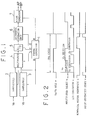
- Fig. 1 is a block diagram illustrating a position detecting apparatus according to one embodiment of this invention.
- This detecting apparatus comprises a timing controller 1, sample/hold circuits 2 and 3, a multiplexer 4, an A/D converter 5 and an arithmetic operation unit 6 and a pulse generator 7.
- the timing controller 1 produces timing pulses a to e for various commands as shown in Fig. 2.
- the sample/hold circuits 2 and 3 perform a sample/hold operation on sinusoidal signals Va and Vb, respectively, in accordance with the hold command a that is output from the timing controller 1 for every constant cycle.
- the multiplexer 4 selectively supplies the sample-held sinusoidal signals Va and Vb to the A/D converter 5 in accordance with the multiplexer select command b from the timing controller 1.
- the A/D converter 5 converts the selected one of the sinusoidal signals Va and Vb into a digital signal which in turn is supplied to the arithmetic operation unit 6.
- this arithmetic operation unit 6 attains a value of ⁇ that sets the right-hand side of equation (2) to 0 using a numerical method, attains the amount of a change in ⁇ , ⁇ , and, from these values, attains the amount of a change in the rotational position, ⁇ .
- the pulse generator 7 is responsive to the pulse generation start command e to output the positional change ⁇ as the number of pulses in the next cycle.
- the sample/hold circuits 2 and 3 respectively sample-holds the sinusoidal signals Va and Vb.
- the multiplexer 4 selects the output of the sample/hold circuit 2 (i.e., the sample-held sinusoidal signal Va) at the beginning stage of the sampling cycle and outputs it to the A/D converter 5.
- the A/D converter 5 converts the signal Va into a digital signal in accordance with the A/D conversion command c from the timing controller 1 and then outputs the digital signal to the arithmetic operation unit 6.
- the multiplexer 4 also responds to the multiplexer select command b whose level has been changed to an H level by the timing controller 1, and selects and supplies the output of the sample/hold circuit 3 (the sinusoidal signal Vb) to the A/D converter 5.
- the A/D converter 5 responds to the A/D conversion command c to convert the signal Vb into a digital signal and outputs it to the arithmetic operation unit 6.
- the arithmetic operation unit 6 then starts an arithmetic operation in response to the numerical method performing command d from the timing controller 1.
- the pulse generator 7 responds to the pulse generation start command e from the timing controller 1 converts pulses whose quantity corresponds to the positional change ⁇ with the signs representing the changing direction of the rotational position into signals AP and BP that are similar to the outputs of the conventional encoder, and then outputs as position data.
- the resolution of the position data depends on the number of bits in the A/D converter 5, the voltage values of the sinusoidal signals Va and Vb can be read with a high accuracy using an A/D converter with a predetermined number of bits.
- the number of bits for the A/D converter 5 and the sampling cycle are properly set, one cycle of the sinusoidal signals (which corresponds to the pitch between the adjacent slits on the rotation code plate) is divided by a desired number (e.g., 1000), and the time-depending positional change in that one cycle is subjected to a so-called internal interpolation.
- a desired number e.g. 1000
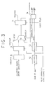
- Fig. 3 illustrates a DDA type pulse generator as an example of the aforementioned pulse generator.
- of the amount of a change in rotational position that is output from the arithmetic operation unit 6 is stored in a register 8 and the sign of
- the values stored in the registers 8 and 12 are respectively transferred to registers 9 and 13 for temporary storage.
- stored in the register 9 and the content of a register 11 are added in an adder 10 and the addition result is stored in the register 11.
- the number of bits of each of the registers 9 and 11 and the adder 10 is n and the number of clock pulses generated during one cycle is 2 n (each command pulse from the timing controller 1 being obtained by frequency-dividing the clock pulse with a proper division factor, for instance), the addition is performed 2 n times that equal the number of the clock pulses produced in one cycle, and the number of times the overflow from the adder 10 occurs is equal to the number of
- /2 n
- overflow pulses that are equal in number to the amount of a change in rotational position
- L e.g., 1000
- the overflow pulse from the adder 10 and the sign from the register 13 are converted by a converter 14 into signals AP and BP that are similar to the outputs from the encoder.
- Fig. 4 is a block diagram illustrating another embodiment where the arithmetic operation unit 6 is replaced with a computer.
- a microprocessor 20 located in the computer generates various commands based on a timing signal coming from the timing controller 1 for every constant cycle. For each constant cycle, the microprocessor 20 sends the hold command a to the individual sample/hold circuits 2 and 3 which are respectively supplied with the sinusoidal signals Va and Vb so as to sample-hold these signals Va and Vb, and sends the multiplexer select command b to the multiplexer 4 which in turn sequentially and selectively transfers the sampled values from the sample/hold circuit 2 and 3 to the A/D converter 5. The digital outputs from the A/D converter 5 are sequentially supplied to the microprocessor 20.
- the microprocessor 20 uses these digital inputs as Va and Vb in equation (1) to calculate the value for ⁇ that sets equation (1) or V to be 0 for each cycle.
- the calculation result or the position data ⁇ for each cycle is sequentially stored in a memory of the computer and the difference ⁇ between the present and previous position data ⁇ is output to the pulse generator 7.
- Fig. 5 illustrates a flowchart for the microprocessor 20 to perform the calculation according to the Newton-Euler law. For every constant cycle, the timing controller 1 generates a timing signal in response to which the microprocessor 20 starts the following sequence of processes.
- the microprocessor 20 After starting the process sequence in step S1, the microprocessor 20 sends the hold command a to the sample/hold circuits 2 and 3 to sample-hold two sinusoidal signals Va and Vb in step S2. In the subsequent step S3 the microprocessor 20 sends the multiplexer select command b to the multiplexer 4 to output the sample-held sinusoidal signals Va and Vb (analog values) to the A/D converter 5 where the analog values are converted into digital values Va and Vb with a predetermined accuracy, and then latches the digital values.
- step S4 the detecting value (position data) ⁇ 0 that has been obtained in the previous cycle is read out and is taken as ⁇ n.
- step S6 it is determined whether or not
- of the difference ⁇ ⁇ - ⁇ 0 between the present detected position data and the previous detected position data ⁇ 0 is calculated taking ⁇ n+1 as new detected position data in that cycle, and the calculated absolute value and the sign of ⁇ are respectively supplied to the registers 8 and 12 of the pulse generator 7. In the subsequent step S9, the new detected position data ⁇ is stored in the memory of the computer and the hold command a is disabled and the arithmetic operation in that cycle is completed (step S10).
- the microprocessor 20 starts the process for the next cycle.
Abstract
Description
- The present invention relates to a pulse distribution type position detecting apparatus and, more particularly but not exclusively, to a pulse type position detecting apparatus which detects the position of a movable section of an NC industrial machine or an arm of a manipulator in motion with a high resolution.
- Conventionally, various position detectors are used to control different types of machines. Resolvers and synchros are discussed in the publication "Machine Design", Vol. 55(1983), Jan., No.1, pp.87-91. Another type of detector is an encoder which generates two sinusoidal signals (indicated by Va and Vb) having a phase difference of 90 degrees therebetween in response to a change in the position of a movable section of a target machine so as to detect the amount and the direction of the positional change of the movable section.
- Conventional encoders direct light emitted from, for example, two light-emitting diodes onto a rotational code plate mounted on a predetermined rotational shaft of the target machine, and cause two light-receiving elements to receive light passing through slits which are provided in the rotational code plate and a fixed slit plate facing the former plate, for photoelectric conversion, whereby sinusoidal signals Va and Vb that have a cycle corresponding to the intervals between the slits of the rotational code plate can be attained in accordance with the rotation of the rotational code plate.
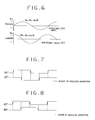
- In this case, to provide a 90-degree phase difference between those two sinusoidal signals Va and Vb (see Fig. 6), the fixed plate is provided with two slits separated at an interval equal to 1/4 of the slit interval on the rotational code plate.
- The individual sinusoidal signals Va and Vb are input to a comparator included in the encoder, which in turn produces output signals AP and BP that become high and low in accordance with the positive and negative levels of the sinusoidal signals and outputs the signals AP and BP to an external unit as the output signals of the encoder. A controller that controls NC machine tools or the like receives the output signals of the encoder and causes an up/down counter located in the controller to perform a count-up or count-down operation to detect the rotational position of the movable section of the target machine when one of predetermined relationships between the signals AP and BP is satisfied, as mentioned later. Based on the detected position, the controller drives a servo motor using a feedback control technique or the like to thereby control the position of the movable section.
- More specifically, a so-called "plus pulse" is generated to sequentially up-count the up/down counter when the rotational code plate, while rotating in a positive direction (e.g., the clockwise direction), reaches a predetermined rotational position, that is:
- (1) when the output signal BP is high at the rising of the output signal AP,
- (2) when the output signal AP is high at the falling of the output signal BP,
- (3) when the output signal BP is low at the falling of the output signal AP, or
- (4) when the output signal AP is low at the rising of the output signal BP. (See Fig. 7.)
- On the other hand, a so-called "minus pulse" is generated to sequentially down-count the up/down counter when the rotational code plate, while rotating in the other direction (the counterclockwise direction in this case), reaches the predetermined rotational position, that is:
- (1) when the output signal BP is low at the rising of the output signal AP,
- (2) when the output signal AP is low at the falling of the output signal BP,
- (3) when the output signal BP is high at the falling of the output signal AP, or
- (4) when the output signal AP is high at the rising of the output signal BP. (See Fig. 8.)
- In the above manner, the rotational angle of the rotational code plate or the rotational position of the rotational shaft on which the rotational code plate is mounted can be detected. With a linearly-moving object, the linear movement is converted into the rotational movement of the rotational code plate.
- According to the conventional position detecting technique, however, as mentioned above, the pulse (either the plus pulse or minus pulse) to drive the up/down counter is simply generated four times during one cycle (corresponding to the interval between the slits formed in the rotational code plate) of the output signal AP or BP in accordance with the rotation of the rotational code plate, so as to detect the rotational position of the rotational code plate four times within that single cycle. Accordingly, if there are 2000 slits arranged on the periphery of the rotational code plate, the resolution attained for the rotational angle detection is simply 1/(2000x4) = 1/8000 rotations. In short, the conventional position detecting technique cannot provide a detection resolution higher than the one corresponding to the circumference of the rotational code plate divided by four times the number of slits.
- As a solution to this problem, the present inventor proposed in the Japanese Patent Disclosure No. 61-110005 a method and an apparatus for effecting the position detection based on the sinusoidal signals Va and Vb with a cycle that corresponds, for example, to 1/1000 of the interval between the slits formed in the rotational code plate. This position detecting method ensures that the moving position of a rotating object or a moving object in general can be detected with a considerably high detection resolution (e.g., 1/(2000x1000 rotations)) as compared with the conventional position detecting method. According to the proposed position detecting method and apparatus, the amount of the movement of the rotating object from the initial position within the intervals between slits is detected in the aforementioned cycle, the detected result is stored in a memory or a register and the stored data is updated for each position detection. To use this method or apparatus with a controller for NC machine tools, it is necessary to provide means for reading out the stored data and subjecting it to data processing in place of the up/down counter. The interface signals between the position detecting apparatus and the controller are significantly complex as compared with the signal AP and BP of the conventional encoder. This makes it difficult to apply the improved position detecting apparatus to an Further attempts to increase resolution in such encoders are disclosed in US-A-4346447 and 4225931, the first of which forms the ratio of the sinusoidal signals to increase resolution, while the second employs circuitry which is present in the precharacterising part of the attached
claim 1. - It is an object of the present invention to provide a pulse distribution type position detecting apparatus that can effect a position detection with a higher resoution, while preferred embodiments thereof may use the same type of interface signals for a controller as are used in the conventional encoder.
- According to the present invention, there is provided a pulse distribution type position detecting apparatus which comprises:
means for generating sinusoidal signals having a phase difference of 90 degrees therebetween in accordance with movement of a moving object;
means for sample-holding voltage values Va and Vb of the sinusoidal signals in a predetermined cycle shorter than that of the sinusoidal signals; and
A/D converting means for converting the voltage values Va and Vb of the sample-held sinusoidal signals into digital signals Va and Vb, respectively; characterised by:
arithmetic operation means for receiving the digital signals Va and Vb from the A/D converting means, calculating in the predetermined cycle a value α that sets
pulse generating means for generating pulses whose quantity corresponds to the difference Δα and represents an amount of movement of the moving object within the predetermined cycle. - As mentioned above, according to the present invention, pulses whose quantity represents the amount of movement of a moving object within a predetermined cycle are produced on the basis of voltage values of two sinusoidal signals, which are generated in accordance with movement of the moving object and have been sampled with a predetermined cycle shorter than that of the sinusoidal signals. Therefore, it is possible to couple the present position detecting apparatus to a controller adapted to use a conventional encoder without modifying the circuitry of the controller and to accurately control the amount of movement of the moving object with a higher resolution.
-
- Fig. 1 is a block diagram of a pulse distribution type position detecting apparatus according to one embodiment of the present invention;
- Fig. 2 is a timing chart illustrating the operational timing of each section of the apparatus shown in Fig. 1;
- Fig. 3 is a detailed block diagram illustrating a pulse generator shown in Fig. 1;
- Fig. 4 is a block diagram of a pulse distribution type position detection apparatus according to another embodiment of the present invention where a computer replaces an arithmetic operation unit shown in Fig. 1;
- Fig. 5 is a flowchart illustrating the operation of the apparatus shown in Fig. 4;
- Fig. 6 is a waveform diagram for explaining a conventional position detecting method;
- Fig. 7 is a view similar to Fig. 6; and
- Fig. 8 is a view similar to Fig. 7.
- To begin with, the operational principle of a pulse distribution type position detecting circuit of the present invention will be explained below. As disclosed in the Japanese Patent Disclosure No. 61-110005, the voltage values Va and Vb of two sinusoidal signals produced in accordance with the rotational angle of a rotational code plate (generally, the moving position of a moving object) are read out for each constant cycle, for example, 50 micro seconds, and a value α is attained which sets the following equation to 0.

Based on thus obtained α, position data (data representing the rotational angle in this case) is obtained by linearly dividing one cycle of the sinusoidal signals with interpolation into a predetermined number of sections (equi-division). (This one cycle corresponds to the interval between adjacent slits on the rotational code plate). The amount of a change in the position data for a constant cycle is converted into a pulse quantity, which ensures position detection with a high resolution. The reason why the position data should be attained in the above method will now be discussed in detail. - In equation (1) above,

where V0 is the amplitude of the two sinusoidal signals and ϑ is the rotational position (rotational angle) of the rotational code plate. Substituting these into equation (1) yields

- Therefore, the value for α that sets V=0 is

- In the case of sinusoidal signal, the value α that sets V=0 is determined as


- When ϑ varies with the rotation of the rotational code plate, therefore, if α is attained with a predetermined sampling cycle shorter than the changing speed of ϑ (specifically, shorter than the time for the sinusoidal signals to change by π with the rotation of the rotational code plate), the amount of a change in ϑ or the rotational angle, Δϑ (the amount of movement from the initial position), can be properly detected from a change Δα. That is, assuming that the present rotational position ϑ is ϑ1, the value for α attained that time is


- This means that the amount of a change in α is Δϑ that is the amount of a change in the rotational position ϑ in one sampling cycle. Accordingly, attaining Δα or the amount of change in α yields Δϑ (amount of a change in the rotational position ϑ) so that the amount of movement of the target object from its initial position can be attained. As should be clear from equation (2), a variation in the amplitude V0 does not influence α which satisfies the relationship of V=0. As a result, the rotational position can be detected without influence from a variation in a gap between the rotational code plate and the fixed slit plate which variation originates from the rotation of the code plate, or a variation in amplitude V0 of the sinusoidal signals Va and Vb which occurs with a variation in the amount of light from light-emitting diodes and source voltage. This prevents the occurrence of a detection error that is originated from these error factors, thus ensuring accurate detection of a rotational position with a high resolution.
- The aforementioned equation (2) is solved using a proper numerical method such as the Newton-Euler law as discussed in the Japanese Patent Disclosure No. 61-110005. Therefore, the sinusoidal signals Va and Vb are sampled for each constant cycle in which the moving object can move a minute amount, and the numerical method is performed for each sampling by using the α attained on the basis of the previous sampled value as the initial value for the present calculation. In this manner, the value α as well as the positional change

- Fig. 1 is a block diagram illustrating a position detecting apparatus according to one embodiment of this invention. This detecting apparatus comprises a
timing controller 1, sample/hold circuits D converter 5 and an arithmetic operation unit 6 and a pulse generator 7. Thetiming controller 1 produces timing pulses a to e for various commands as shown in Fig. 2. The sample/hold circuits timing controller 1 for every constant cycle. The multiplexer 4 selectively supplies the sample-held sinusoidal signals Va and Vb to the A/D converter 5 in accordance with the multiplexer select command b from thetiming controller 1. In response to the A/D conversion command c from thetiming controller 1, the A/D converter 5 converts the selected one of the sinusoidal signals Va and Vb into a digital signal which in turn is supplied to the arithmetic operation unit 6. In accordance with the numerical method performing command d, this arithmetic operation unit 6 attains a value of α that sets the right-hand side of equation (2) to 0 using a numerical method, attains the amount of a change in α, Δα, and, from these values, attains the amount of a change in the rotational position, Δϑ. The pulse generator 7 is responsive to the pulse generation start command e to output the positional change Δϑ as the number of pulses in the next cycle. - The operation of the detecting apparatus according to this embodiment will now be explained.
- When the hold command a as shown in Fig. 2 is output from the
timing controller 1, the sample/hold circuits timing controller 1, the multiplexer 4 selects the output of the sample/hold circuit 2 (i.e., the sample-held sinusoidal signal Va) at the beginning stage of the sampling cycle and outputs it to the A/D converter 5. The A/D converter 5 converts the signal Va into a digital signal in accordance with the A/D conversion command c from thetiming controller 1 and then outputs the digital signal to the arithmetic operation unit 6. The multiplexer 4 also responds to the multiplexer select command b whose level has been changed to an H level by thetiming controller 1, and selects and supplies the output of the sample/hold circuit 3 (the sinusoidal signal Vb) to the A/D converter 5. The A/D converter 5 responds to the A/D conversion command c to convert the signal Vb into a digital signal and outputs it to the arithmetic operation unit 6. The arithmetic operation unit 6 then starts an arithmetic operation in response to the numerical method performing command d from thetiming controller 1. Specifically, based on the digital signals Va and Vb, the arithmetic operation unit 6 solves the linear equation (1)

using the proper numerical method with the previously-attained α as the initial value so as to attain a new α, calculates the difference between the previous α and the new α and outputs the difference as the amount of a positional change. - Suppose that the linear equation is solved using the Newton-Euler law. Then, given

the derivative, V'(α), of V(α) with respect to α is

and an approximate solution for the linear equation can be attained by repeating the calculations given below. - To attain position data α i in one detection cycle, first αi1 = αi0 + Δαi0 is obtained using position data αi-1 that has been attained in the previous cycle as the initial approximation of αi (αi-1= i0 to specify the 0-th approximation) and αi1 is taken as the first approximation of αi. Here,

- Provided that α in is the n-th approximation obtained by repeating the above calculation process, the (n+1)-th approximation is given by the following equation.

where
- When the absolute value of Δαin, |Δαin|, is |Δαin| <ε (where ε is a predetermined minute amount of positional change according to the requested detection accuracy), the repetition of the calculation is stopped and with the approximate solution αi(n+1) taken as position data αi in that detection cycle, the difference between this position data αi and the previously-obtained position data αi-1,

timing controller 1 converts pulses whose quantity corresponds to the positional change Δϑ with the signs representing the changing direction of the rotational position into signals AP and BP that are similar to the outputs of the conventional encoder, and then outputs as position data. As the resolution of the position data depends on the number of bits in the A/D converter 5, the voltage values of the sinusoidal signals Va and Vb can be read with a high accuracy using an A/D converter with a predetermined number of bits. According to the apparatus of the present embodiment, to provide position data with a high resolution, the number of bits for the A/D converter 5 and the sampling cycle are properly set, one cycle of the sinusoidal signals (which corresponds to the pitch between the adjacent slits on the rotation code plate) is divided by a desired number (e.g., 1000), and the time-depending positional change in that one cycle is subjected to a so-called internal interpolation. - Fig. 3 illustrates a DDA type pulse generator as an example of the aforementioned pulse generator. The absolute value |Δα| of the amount of a change in rotational position that is output from the arithmetic operation unit 6 is stored in a
register 8 and the sign of |Δα| is stored in aregister 12. In accordance with the pulse generation start command e from thetiming controller 1, the values stored in theregisters registers 9 and 13 for temporary storage. And every time a clock pulse is generated from a clock pulse generator (not shown), the value |Δα| stored in the register 9 and the content of aregister 11 are added in anadder 10 and the addition result is stored in theregister 11. Provided that the number of bits of each of theregisters 9 and 11 and theadder 10 is n and the number of clock pulses generated during one cycle is 2n (each command pulse from thetiming controller 1 being obtained by frequency-dividing the clock pulse with a proper division factor, for instance), the addition is performed 2n times that equal the number of the clock pulses produced in one cycle, and the number of times the overflow from theadder 10 occurs is equal to the number of |Δα| set in the register 9 (2nx|Δα|/2n = |Δα|). As a result, overflow pulses that are equal in number to the amount of a change in rotational position |Δα| = |Δϑ| are output from theadder 10. Since the sign of Δα is output from theregister 13, the change in rotational position Δα = Δϑ output has the plus or minus directivity. For instance, given that L (e.g., 1000) is the number of divided sections of the interval (one pitch) of the adjacent slits on the rotational code plate with interpolation, ϑ in one slit cycle is 2π radians so that the interpolation division is carried out with the unit of 2π/L (= 2π/1000), thus ensuring the detection of the change in rotational position Δα = Δϑ with a high resolution. The overflow pulse from theadder 10 and the sign from theregister 13 are converted by aconverter 14 into signals AP and BP that are similar to the outputs from the encoder. - Fig. 4 is a block diagram illustrating another embodiment where the arithmetic operation unit 6 is replaced with a computer. A
microprocessor 20 located in the computer generates various commands based on a timing signal coming from thetiming controller 1 for every constant cycle. For each constant cycle, themicroprocessor 20 sends the hold command a to the individual sample/hold circuits hold circuit D converter 5. The digital outputs from the A/D converter 5 are sequentially supplied to themicroprocessor 20. Using these digital inputs as Va and Vb in equation (1), themicroprocessor 20 calculates the value for α that sets equation (1) or V to be 0 for each cycle. The calculation result or the position data α for each cycle is sequentially stored in a memory of the computer and the difference Δα between the present and previous position data α is output to the pulse generator 7. - Fig. 5 illustrates a flowchart for the
microprocessor 20 to perform the calculation according to the Newton-Euler law. For every constant cycle, thetiming controller 1 generates a timing signal in response to which themicroprocessor 20 starts the following sequence of processes. - After starting the process sequence in step S1, the
microprocessor 20 sends the hold command a to the sample/hold circuits microprocessor 20 sends the multiplexer select command b to the multiplexer 4 to output the sample-held sinusoidal signals Va and Vb (analog values) to the A/D converter 5 where the analog values are converted into digital values Va and Vb with a predetermined accuracy, and then latches the digital values. - In step S4, the detecting value (position data) α0 that has been obtained in the previous cycle is read out and is taken as αn.
- In the next step S5, the following calculations are performed:

and

where n=0, 1, 2, ... and the calculation should start with n=0. - In step S6 it is determined whether or not |Δαn| is smaller than ε, which is a value to define the detection accuracy error and is given in advance. If the decision in step S6 is negative, the value αn+1 is set as a new αn (step S7) and the above calculations are performed again. On the other hand, if the decision in step S6 is affirmative, the flow advances to step S8 where the absolute value |Δα| of the difference Δα = α - α0 between the present detected position data and the previous detected position data α0 is calculated taking αn+1 as new detected position data in that cycle, and the calculated absolute value and the sign of Δα are respectively supplied to the
registers - Then, the
microprocessor 20 starts the process for the next cycle. During this period, as described above, the pulse generator 7 outputs the pulses AP and BP which correspond in number to the change in rotational position, Δα = Δϑ, in accordance with the pulse generation start command e from thetiming controller 1. Consequently, the position data can be interpolatively detected with high resolution within the interval between the slits on the rotational code plate.
Claims (3)
- A pulse distribution type position detecting apparatus, comprising:
means for generating sinusoidal signals having a phase difference of 90 degrees therebetween in accordance with movement of a moving object;
means (2,3) for sample-holding voltage values Va and Vb of said sinusoidal signals in a predetermined cycle shorter than that of said sinusoidal signals; and
A/D converting means (5) for converting said voltage values Va and Vb of said sample-held sinusoidal signals into digital signals Va and Vb, respectively; characterised by:
arithmetic operation means (6) for receiving said digital signals Va and Vb from said A/D converting means, calculating in said predetermined cycle a value α that sets
pulse generating means (7) for generating pulses whose quantity corresponds to said difference Δα and represents an amount of movement of said moving object within said predetermined cycle. - A pulse distribution type position detecting apparatus according to claim 1, wherein said arithmetic operation means (6) is operable to repeatedly calculate a new value α according to the Newton-Euler law with said previously-attained valued α as an initial value until the difference between said previously-attained value and said new value becomes a predetermined minute value.
- A pulse distribution type position detecting apparatus according to claim 1 or 2, wherein said pulse generating means (7) comprises a first register (9) for storing an absolute value of said value α, a second register (11), an adder (10) for adding contents of said first and second registers (9,11) and outputting an addition result to said second register (11), a third register (13) for storing a sign of said value α, and a converter (14) for producing pulse signals AP and BP having a 90-degree phase difference therebetween from an output of said third register (13) and an overflow pulse which is produced when an overflow occurs in said adder (10).
Applications Claiming Priority (2)
| Application Number | Priority Date | Filing Date | Title |
|---|---|---|---|
| JP61029023A JPS62187210A (en) | 1986-02-14 | 1986-02-14 | Pulse distribution type position detecting device |
| JP29023/86 | 1986-02-14 |
Publications (3)
| Publication Number | Publication Date |
|---|---|
| EP0257100A1 EP0257100A1 (en) | 1988-03-02 |
| EP0257100A4 EP0257100A4 (en) | 1990-12-12 |
| EP0257100B1 true EP0257100B1 (en) | 1992-04-29 |
Family
ID=12264818
Family Applications (1)
| Application Number | Title | Priority Date | Filing Date |
|---|---|---|---|
| EP87901632A Expired - Lifetime EP0257100B1 (en) | 1986-02-14 | 1987-02-14 | Pulse distribution type position detector |
Country Status (5)
| Country | Link |
|---|---|
| EP (1) | EP0257100B1 (en) |
| JP (1) | JPS62187210A (en) |
| KR (1) | KR900005879B1 (en) |
| DE (1) | DE3778609D1 (en) |
| WO (1) | WO1987005101A1 (en) |
Families Citing this family (6)
| Publication number | Priority date | Publication date | Assignee | Title |
|---|---|---|---|---|
| JPH01141308A (en) * | 1987-11-27 | 1989-06-02 | Dainippon Screen Mfg Co Ltd | Measuring instrument using encoder |
| US4912661A (en) * | 1987-12-01 | 1990-03-27 | Hewlett-Packard Company | Tracking and resampling method and apparatus for monitoring the performance of rotating machines |
| DE19530386A1 (en) * | 1995-08-18 | 1997-02-20 | Philips Patentverwaltung | Position sensor |
| US7191527B2 (en) | 2005-08-02 | 2007-03-20 | Electro-Sensors, Inc. | Linear distance measurement by non-driven arm |
| JP4957192B2 (en) * | 2006-11-06 | 2012-06-20 | 株式会社デンソー | Rotation angle detection device and rotation angle detection method |
| US7444751B1 (en) | 2007-09-28 | 2008-11-04 | Electro-Sensors, Inc. | Linear distance measurement by non-driven arm |
Family Cites Families (4)
| Publication number | Priority date | Publication date | Assignee | Title |
|---|---|---|---|---|
| DE2729697A1 (en) * | 1977-07-01 | 1979-01-04 | Heidenhain Gmbh Dr Johannes | METHOD OF INTERPOLATION |
| JPS56118611A (en) * | 1980-02-25 | 1981-09-17 | Nippon Kogaku Kk <Nikon> | Highly accurate split reader for signal |
| US4547858A (en) * | 1983-06-13 | 1985-10-15 | Allied Corporation | Dynamic control for manipulator |
| JPS61120920A (en) * | 1984-11-19 | 1986-06-09 | Asahi Optical Co Ltd | Encoder type angle and length measuring circuit |
-
1986
- 1986-02-14 JP JP61029023A patent/JPS62187210A/en active Pending
-
1987
- 1987-02-14 EP EP87901632A patent/EP0257100B1/en not_active Expired - Lifetime
- 1987-02-14 WO PCT/JP1987/000097 patent/WO1987005101A1/en active IP Right Grant
- 1987-02-14 KR KR1019870700864A patent/KR900005879B1/en active Search and Examination
- 1987-02-14 DE DE8787901632T patent/DE3778609D1/en not_active Expired - Lifetime
Also Published As
| Publication number | Publication date |
|---|---|
| DE3778609D1 (en) | 1992-06-04 |
| KR900005879B1 (en) | 1990-08-13 |
| KR880700941A (en) | 1988-04-13 |
| EP0257100A1 (en) | 1988-03-02 |
| WO1987005101A1 (en) | 1987-08-27 |
| JPS62187210A (en) | 1987-08-15 |
| EP0257100A4 (en) | 1990-12-12 |
Similar Documents
| Publication | Publication Date | Title |
|---|---|---|
| EP0331189B1 (en) | Position/speed detection method and apparatus | |
| US4933674A (en) | Method and apparatus for correcting resolver errors | |
| US5202842A (en) | Rotational position detecting device which compensates for eccentricity of rotating object | |
| EP0257100B1 (en) | Pulse distribution type position detector | |
| EP0199826B1 (en) | Method of detecting position | |
| Lygouras et al. | High-performance position detection and velocity adaptive measurement for closed-loop position control | |
| US4837492A (en) | Apparatus for detecting revolution using a synchro | |
| JPH0565827B2 (en) | ||
| EP0200791A1 (en) | Method and apparatus for detecting position | |
| US5065081A (en) | Zero error digital servo system | |
| JP3341775B2 (en) | Digital servo circuit | |
| JPH0521166B2 (en) | ||
| JPH1038616A (en) | Method and device for calculating phase | |
| JPH0719849A (en) | Apparatus and method for reading position | |
| SU1213543A1 (en) | Shaft turn angle-to-digital converter | |
| JP4227352B2 (en) | Coincidence detection apparatus and method | |
| SU1042058A1 (en) | Shaft turn angle to code converter | |
| JPH1062203A (en) | Position detector | |
| JPS6161125B2 (en) | ||
| SU645190A1 (en) | Shaft angular position-to-code converter | |
| JPH0342766B2 (en) | ||
| JPH02173522A (en) | Position detector | |
| SU1277064A1 (en) | Device for generating error signal | |
| JPH0629723B2 (en) | Absolute position measuring method and device | |
| JPH07167877A (en) | Method and apparatus for detecting displacing speed |
Legal Events
| Date | Code | Title | Description |
|---|---|---|---|
| PUAI | Public reference made under article 153(3) epc to a published international application that has entered the european phase |
Free format text: ORIGINAL CODE: 0009012 |
|
| 17P | Request for examination filed |
Effective date: 19871028 |
|
| AK | Designated contracting states |
Kind code of ref document: A1 Designated state(s): DE FR GB |
|
| A4 | Supplementary search report drawn up and despatched |
Effective date: 19901030 |
|
| AK | Designated contracting states |
Kind code of ref document: A4 Designated state(s): DE FR GB |
|
| 17Q | First examination report despatched |
Effective date: 19910315 |
|
| GRAA | (expected) grant |
Free format text: ORIGINAL CODE: 0009210 |
|
| AK | Designated contracting states |
Kind code of ref document: B1 Designated state(s): DE FR GB |
|
| REF | Corresponds to: |
Ref document number: 3778609 Country of ref document: DE Date of ref document: 19920604 |
|
| ET | Fr: translation filed | ||
| PG25 | Lapsed in a contracting state [announced via postgrant information from national office to epo] |
Ref country code: FR Effective date: 19920918 |
|
| PG25 | Lapsed in a contracting state [announced via postgrant information from national office to epo] |
Ref country code: GB Effective date: 19930214 |
|
| PLBE | No opposition filed within time limit |
Free format text: ORIGINAL CODE: 0009261 |
|
| STAA | Information on the status of an ep patent application or granted ep patent |
Free format text: STATUS: NO OPPOSITION FILED WITHIN TIME LIMIT |
|
| 26N | No opposition filed | ||
| GBPC | Gb: european patent ceased through non-payment of renewal fee |
Effective date: 19930214 |
|
| REG | Reference to a national code |
Ref country code: FR Ref legal event code: ST |
|
| PGFP | Annual fee paid to national office [announced via postgrant information from national office to epo] |
Ref country code: DE Payment date: 19980220 Year of fee payment: 12 |
|
| PG25 | Lapsed in a contracting state [announced via postgrant information from national office to epo] |
Ref country code: DE Free format text: LAPSE BECAUSE OF NON-PAYMENT OF DUE FEES Effective date: 19991201 |