JP4227352B2 - Coincidence detection apparatus and method - Google Patents
Coincidence detection apparatus and method Download PDFInfo
- Publication number
- JP4227352B2 JP4227352B2 JP2002113628A JP2002113628A JP4227352B2 JP 4227352 B2 JP4227352 B2 JP 4227352B2 JP 2002113628 A JP2002113628 A JP 2002113628A JP 2002113628 A JP2002113628 A JP 2002113628A JP 4227352 B2 JP4227352 B2 JP 4227352B2
- Authority
- JP
- Japan
- Prior art keywords
- pulse
- pulses
- value
- counter
- coincidence detection
- Prior art date
- Legal status (The legal status is an assumption and is not a legal conclusion. Google has not performed a legal analysis and makes no representation as to the accuracy of the status listed.)
- Expired - Fee Related
Links
Images


Classifications
-
- G—PHYSICS
- G01—MEASURING; TESTING
- G01D—MEASURING NOT SPECIALLY ADAPTED FOR A SPECIFIC VARIABLE; ARRANGEMENTS FOR MEASURING TWO OR MORE VARIABLES NOT COVERED IN A SINGLE OTHER SUBCLASS; TARIFF METERING APPARATUS; MEASURING OR TESTING NOT OTHERWISE PROVIDED FOR
- G01D5/00—Mechanical means for transferring the output of a sensing member; Means for converting the output of a sensing member to another variable where the form or nature of the sensing member does not constrain the means for converting; Transducers not specially adapted for a specific variable
- G01D5/12—Mechanical means for transferring the output of a sensing member; Means for converting the output of a sensing member to another variable where the form or nature of the sensing member does not constrain the means for converting; Transducers not specially adapted for a specific variable using electric or magnetic means
- G01D5/244—Mechanical means for transferring the output of a sensing member; Means for converting the output of a sensing member to another variable where the form or nature of the sensing member does not constrain the means for converting; Transducers not specially adapted for a specific variable using electric or magnetic means influencing characteristics of pulses or pulse trains; generating pulses or pulse trains
- G01D5/24404—Interpolation using high frequency signals
Description
【0001】
【発明の属する技術分野】
本発明は、移動または回転する物体が、ある決められた位置又は角度を通過するときに一致信号を出力する装置及び方法に関する。
【0002】
【従来の技術】
従来より、物体を移動又は回転させて、ある決められた位置又は角度を通過するときに一致信号を出力する装置が知られている。これらの装置は静電容量センサやエンコーダで変位又は角度を検出する。
【0003】
静電容量センサは直接変位又は角度情報を連続時間で出力するので、その情報を例えば電圧値などに変換し、物体の現在位置または角度を上記の決められた位置または角度とそのまま比較できる。
【0004】
エンコーダの場合はそのエンコーダの基本周期またはゼロクロスをカウントすることにより、物体の現在位置または角度を決められた位置または角度とそのまま比較できる。
【0005】
高精度な用途では、基本周期を分割して分解能を上げる方法が用いられる。
【0006】
従来これらの用途にはアナログ分割方式が用いられていた。
【0007】
アナログ分割方式では連続時間で周期信号を出力するため、これをカウントすることにより、物体の現在位置または角度を決められた位置または角度と比較することができる。
【0008】
アナログ分割方式とは電気回路により、エンコーダの周期信号を基本周期より短い周期に変換するものである。
【0009】
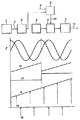
図6は、エンコーダを例にあげて従来例を説明する図である。
【0010】
物体の移動又は回転とともにエンコーダ1から二相出力2が出力される。これらは位相の90°異なるサイン波状の信号である。これをアナログ分割器30で電気的に処理することで一周期に対して何周期かの周期信号31を生成する。ここでは4分割の場合を示している。
【0011】
アナログ分割器ではこのように動きに合わせて連続的に信号が出力される。この信号をカウンタ6でカウントして信号32を得る。一致検出の目標9をNパルス目とすると11で示されるタイミングで一致検出信号が出力される。
【0012】
以上のようにアナログ分割器の出力であれば、それをカウントすることでアナログ分割器の分解能で一致検出をすることができる。
【0013】
【発明が解決しようとする課題】
しかしながら、さらに高精度にするために、たとえば1000分割以上にする場合は、アナログ分割方式では回路規模が増大し、コスト、信号調整の手間などから実現は困難である。
【0014】
さらに、アナログ分割方式では最終的な分解能をカウントするため、分割数を上げるとカウンタの桁数が増加し、かつ、速度が同じであっても分解能に比例して周波数が高くなるのでカウンタ自体も高速化が要求される。
【0015】
以上のように、アナログ分割方式では2つの課題がある。
【0016】
これらの課題を解決するためデジタル信号処理で分割するデジタル分割器(方式)が提案されている。
【0017】
デジタル分割器はアナログデジタル変換器とデジタル信号処理部とから構成されるため、分割数を上げても回路規模は増加しないという利点がある。
【0018】
デジタル分割器を制御装置と組み合わせて、位置決め装置などで静止状態での性能を要求する場合はアナログ分割器と同様に使用することが可能である。
【0019】
ところが、デジタル分割器は、サンプリング毎に変位又は角度情報が得られる構成であるため、サンプリングの間の情報は得られない。
【0020】
これは一致検出を高精度で行いたい場合には不都合である。
【0021】
従って、本発明は上述した課題に鑑みてなされたものであり、その目的は、回路規模の増大を防止しながら、高精度で高速な一致検出を可能とすることである。
【0022】
【課題を解決するための手段】
上述した課題を解決し、目的を達成するために、本発明に係わる一致検出装置は、ほぼ一定の速度で移動する物体の変位又は角度の目標位置に対する一致を検出する一致検出装置であって、物体の変位又は角度に応じて少なくとも2つの周期信号を出力する検出器と、該検出器から出力される周期信号を一定の時間間隔でサンプリングし、サンプリング毎に前記周期信号の周期より細かい変位又は角度に対応する位置パルス数を出力するデジタル分割器と、周波数が一定の連続パルスを生成するパルス生成装置と、前記物体の目標位置に対応する位置パルス数と前記物体の現在位置に対応する位置パルス数との差に対応する位置パルス数を前記パルス生成装置のパルス数に換算するパルス換算装置と、前記パルス生成装置の出力であるパルス信号をカウントすると共にカウント値が前記サンプリング毎に更新されるカウンタであって、サンプリング周期の1周期内に前記パルス生成装置が生成するパルス数の少なくとも2倍に相当する容量を有し、前記差に対応する前記位置パルス数が前記1周期内に前記物体が移動する移動量に相当する位置パルス数より大きい場合は、前記1周期内に前記パルス生成装置が生成するパルス数より大きい、前記カウンタの最大値として予め定められた値を、更新する値として設定するとともに、前記差に対応する前記位置パルス数が前記1周期内に前記物体が移動する移動量に相当する位置パルス数以下の場合は、前記換算された前記パルス数を、更新する値として設定するカウンタと、前記カウンタに設定される設定値が正の場合は、前記設定値から前記パルス生成装置からのパルス数を減算してゼロになった時点で一致検出信号を出力し、前記設定値がゼロまたは負であるときには、直ちに一致検出信号を出力する一致検出手段と、を具備することを特徴としている。
【0023】
また、この発明に係わる一致検出装置において、前記カウンタを更新するタイミングと更新する値は、前記デジタル分割器の処理時間の遅れ分を補正したタイミングと値であることを特徴としている。
【0024】
【0025】
また、本発明に係わる一致検出方法は、ほぼ一定の速度で移動する物体の変位又は角度の目標位置に対する一致を検出する一致検出方法であって、物体の変位又は角度応じて少なくとも2つの周期信号を出力する検出器により前記物体の変位を検出する検出工程と、該検出工程において出力される周期信号を一定の時間間隔でサンプリングし、サンプリング毎に前記周期信号の周期より細かい変位又は角度に対応する位置パルス数を出力するデジタル分割器により前記周期信号を処理するデジタル分割工程と、パルス生成装置により周波数が一定の連続パルスを生成するパルス生成工程と、前記物体の目標位置に対応する情報と前記物体の現在位置に対応する情報との差に対応する位置パルス数を前記パルス生成装置のパルス数に換算するパルス換算工程と、前記パルス生成装置の出力であるパルス信号をカウントするカウンタにより前記パルス信号をカウントすると共にカウント値が前記サンプリング毎に更新されるカウント工程であって、サンプリング周期の1周期内に前記パルス生成装置が生成するパルス数の少なくとも2倍に相当する容量を有する前記カウンタに対して、前記差に対応する位置パルス数が前記1周期内に前記物体が移動する移動量に相当する位置パルス数より大きい場合は、前記1周期内に前記パルス生成装置が生成するパルス数より大きい、前記カウンタの最大値として予め定められた値を、更新する値として設定するとともに、前記差に対応する前記位置パルス数が前記1周期内に前記物体が移動する移動量に相当する位置パルス数以下の場合は、前記換算されたパルス数を、更新する値として設定するカウント工程と、前記カウンタに設定される設定値が正の場合は、前記設定値から前記パルス生成装置からのパルス数を減算してゼロになった時点で一致検出信号を出力し、前記設定値がゼロまたは負であるときには、直ちに一致検出信号を出力する一致検出工程と、を具備することを特徴としている。
【0026】
また、この発明に係わる一致検出方法において、前記カウンタを更新するタイミングと更新する値は、前記デジタル分割器の処理時間の遅れ分を補正したタイミングと値であることを特徴としている。
【0027】
【0028】
【0029】
【0030】
【0031】
【0032】
【0033】
【0034】
【0035】
【0036】
【発明の実施の形態】
以下、本発明の好適な実施形態について説明する。
【0037】
(第1の実施形態)
図1は、本発明の一致検出装置の第1の実施形態の構成を示す図である。
【0038】
なお、図1においては、従来例を示す図7と同一機能部分には、同一符号を付している。
【0039】
図1において、1はエンコーダ、2はエンコーダの出力信号、3はデジタル分割器、4はデジタル分割器の出力信号、5はパルス列生成装置、6はカウンタ、7は一致検出部、8はパルス換算部、9は一致検出のための目標位置情報信号、10はカウンタ設定情報信号、11は一致信号である。
【0040】
まず、デジタル分割器3の動作について説明する。
【0041】
物体の移動又は回転により、エンコーダ1は2のような二相の周期信号を出力する。
【0042】
デジタル分割器3は、信号2の逆正接関数に相当する値を計算する。これはエンコーダ信号2の一周期毎の三角波12となる。また、基本周期をカウントし階段状の信号13を得る。
【0043】
これらの2つの信号を足し合わせたものが、分割した後の最終的な変位又は角度情報を表す信号4となる。
【0044】
たとえば1000分割するときには三角波は0から999までの値を取り、基本周期のカウントの重みを1000にして加算する。
【0045】
これらの処理はアナログデジタル変換器とデジタル信号処理回路の組み合わせで実行される。信号4は連続して出力されるわけではなく、サンプリング毎、すなわち矢印14のタイミングで出力され、その時の信号4の高さが分割値の出力で、隣り合う2つの矢印14の間の分割値は分からない。
【0046】
実際には分割値を算出するためにはデジタル信号処理の時間が必要であり、14のタイミングから一定時間遅れて15のタイミングでデジタル分割器の出力が利用可能となる。
【0047】
この関係を図2を参照して説明する。図2において、横軸が時間、縦軸が変位又は角度の移動量を示す位置パルス数を示す。
【0048】
4が対象物の時間に対する移動量を示す。14がサンプル点で、その時点の位置パルス数をN(k)とする。kはk番目のサンプル点14を示す。
【0049】
14から15までの時間がデジタル分割の処理時間遅れで、15の時点でN(k)が計算される。
【0050】
計算時間遅れの間に、物体は△だけ移動しているので、15の時点での位置パルス数はN(k)+△である。
【0051】
対象物(物体)の速度がほぼ一定であれば△はサンプル点によらずほぼ一定であるとみなすことができる。
【0052】
【0053】
【0054】
一致検出を実行するとき、対象物は図示しない制御装置によって一定の速度で移動又は回転する。サンプリングの間隔は既知であるのでサンプリングの間に移動する変位又は角度に相当する位置パルス数はあらかじめわかっている。その位置パルス数をMとする。また、パルス生成装置がサンプリングの間に生成するパルス数をNpとする。
【0055】
図2で、k番目のサンプル点の位置パルス数N(k) とk+1番目のサンプル点の位置パルス数N(k+1) の差がMに相当する。
【0056】
デジタル分割を行う場合、制御装置もデジタル分割値を使用してデジタル処理を行うのが一般的で、このときデジタル信号処理部は共通に使えるので回路規模の増大はない。
【0057】
カウンタ6は少なくとも二サンプル分の容量すなわちNpの2倍までカウント可能とする。
【0058】
デジタル分割器3はサンプル点14毎の変位又は角度を位相比較信号15のタイミングで出力できる。
【0059】
移動速度はほぼ一定とみなせるので14から15までに移動する位置パルス数は計算可能である。
【0060】
カウンタ6の値の設定を図3に示すフローチャートを参照して説明する。
【0061】
図3において、Neqは一致検出の目標位置パルス数、N(k)はk番目のサンプル時の位置パルス数、△は計算時間の間に移動する位置パルス数、Ndiffは目標位置との差、Nmaxはカウンタの最大値である。
【0062】
この位置パルス数と一致検出の目標位置パルス数との差を図1及び図2に示す15のタイミングで計算する。
【0063】
ステップS1:タイミング15のときの位置パルス数N(k) + △を計算する。
【0064】
ステップS2:目標位置パルス数との差Ndiffを計算する。
【0065】
ステップS3:Ndiffが1つのサンプル間隔の間に移動する位置パルス数Mを越えるかどうか判断する。
【0066】
ステップS4:Mを越えるときはカウンタの最大値Nmaxをカウンタに設定する。
【0067】
ステップS5:M以下のときは、Ndiffをパルス生成装置のパルス数のNcに換算する。
【0068】
換算式
Nc = (Ndiff / M ) * Np
ステップS6:カウンタ6にNc を設定する。
【0069】
カウンタ6はパルス生成装置5からのパルスを設定値Nmax または Ncから減算するようにカウントする。
【0070】
カウンタの値と一致検出部7の時間関係を図4を参照して説明する。
【0071】
横軸が時間、縦軸がカウンタの値である。
【0072】
15のタイミングでカウンタの値はNmaxかNcに設定される。
【0073】
(a)ではNcが正の場合で減算した値が0になれば一致検出信号を出力する。
【0074】
(b)ではNcが負になった場合でこのときは15のタイミングで一致検出信号を出力する。
【0075】
このときは一致信号に時間差ができるが、アナログ分割の方法に比べて1パルスあたりの分解能が格段に上がっているので変位又は角度誤差では非常に小さいとみなせる。
【0076】
【0077】
(第2の実施形態)
第1の実施形態では、パルス生成装置の周波数を一定としたが、任意の周波数のパルスを生成する素子で置き換えても同様の処理が可能である。
【0078】
図5に第2の実施形態を示す。
【0079】
18がパルス生成素子で、その他は第1の実施形態と同じである。
【0080】
第1の実施形態では、カウンタに設定する値を目標値とデジタル分割器の出力の差から換算したが、MとNpを一致させれば換算を省略できる。
【0081】
第2の実施形態の説明では、パルス列生成装置を独立した素子として説明したが、現在ではFPGAのように機能をプログラムできる素子が開発されている。これらの素子を利用して、パルス列生成機能と他の機能(たとえばカウンタ)を一つの素子の中で実現することも可能である。
【0082】
以上説明したように、上記の実施形態によれば、時間的に離散した分割器出力から時間的に連続した変位パルス列を生成することにより、高精度と即時性を兼ね備えた一致検出を行なうことが可能となる。
【0083】
また、カウンタの桁数を小さくすることができるので、カウンタの回路規模及び処理回路の規模が大型化することを防止できる。
【0084】
【発明の効果】
以上説明したように、本発明によれば、回路規模の増大を防止しながら、高精度で高速な一致検出が可能となる。
【図面の簡単な説明】
【図1】 本発明の第1の実施形態を示す図である。
【図2】 デジタル分割器の処理時間を説明する図である。
【図3】 差分計算手順を説明するフローチャートである。
【図4】 本発明の実施形態の一致検出の様子を説明する図である。
【図5】 本発明の第2の実施形態を説明する図である。
【図6】 従来例を示す図である。
【符号の説明】
1 エンコーダ
2 エンコーダの出力信号
3 デジタル分割器
4 デジタル分割器の出力
5 パルス列生成装置
6 カウンタ
7 一致検出部
8 パルス換算部
9 一致検出のための情報
10 カウンタ設定情報
11 一致信号
12 一周期ごとの三角波
13 基本周期のカウント
14 サンプル点
15 デジタル分割処理後のタイミング
18 パルス生成素子
30 アナログ分割器
31 アナログ分割器の出力
32 カウンタの出力[0001]
BACKGROUND OF THE INVENTION
The present invention relates to an apparatus and method for outputting a coincidence signal when a moving or rotating object passes a certain position or angle.
[0002]
[Prior art]
2. Description of the Related Art Conventionally, there is known a device that outputs a coincidence signal when an object is moved or rotated to pass a predetermined position or angle. These devices detect displacement or angle by a capacitance sensor or an encoder.
[0003]
Since the capacitance sensor directly outputs displacement or angle information in continuous time, the information can be converted into a voltage value, for example, and the current position or angle of the object can be directly compared with the determined position or angle.
[0004]
In the case of an encoder, the current position or angle of the object can be directly compared with the determined position or angle by counting the basic period or zero cross of the encoder.
[0005]
For high-precision applications, a method of dividing the fundamental period to increase the resolution is used.
[0006]
Conventionally, an analog division method has been used for these applications.
[0007]
In the analog division method, since a periodic signal is output in continuous time, the current position or angle of the object can be compared with the determined position or angle by counting the signal.
[0008]
In the analog division method, the periodic signal of the encoder is converted to a cycle shorter than the basic cycle by an electric circuit.
[0009]
FIG. 6 is a diagram for explaining a conventional example by taking an encoder as an example.
[0010]
A two-
[0011]
In the analog divider, signals are continuously output in accordance with the movement in this way. This signal is counted by the
[0012]
As described above, if it is the output of the analog divider, it is possible to detect coincidence with the resolution of the analog divider by counting the output.
[0013]
[Problems to be solved by the invention]
However, in order to achieve higher accuracy, for example, when the number of divisions is 1000 or more, the analog division method increases the circuit scale, and is difficult to realize due to cost and labor of signal adjustment.
[0014]
Furthermore, since the final resolution is counted in the analog division method, increasing the number of divisions increases the number of digits of the counter, and even if the speed is the same, the frequency increases in proportion to the resolution. High speed is required.
[0015]
As described above, the analog division method has two problems.
[0016]
In order to solve these problems, a digital divider (system) that divides by digital signal processing has been proposed.
[0017]
Since the digital divider is composed of an analog-digital converter and a digital signal processor, there is an advantage that the circuit scale does not increase even if the number of divisions is increased.
[0018]
When a digital divider is combined with a control device and performance in a stationary state is required by a positioning device or the like, it can be used in the same manner as an analog divider.
[0019]
However, since the digital divider is configured to obtain displacement or angle information for each sampling, information during sampling cannot be obtained.
[0020]
This is inconvenient when it is desired to perform coincidence detection with high accuracy.
[0021]
Accordingly, the present invention has been made in view of the above-described problems, and an object thereof is to enable high-precision and high-speed coincidence detection while preventing an increase in circuit scale.
[0022]
[Means for Solving the Problems]
In order to solve the above-described problems and achieve the object, a coincidence detection apparatus according to the present invention is a coincidence detection apparatus that detects a coincidence of a displacement or an angle of an object moving at a substantially constant speed with respect to a target position, A detector that outputs at least two periodic signals in accordance with the displacement or angle of the object, and a periodic signal output from the detector are sampled at a constant time interval, and a displacement smaller than the period of the periodic signal at each sampling or A digital divider that outputs the number of position pulses corresponding to an angle; a pulse generator that generates a continuous pulse with a constant frequency; the number of position pulses corresponding to the target position of the object; and the position corresponding to the current position of the object a pulse conversion unit for converting the position number of pulses corresponding to the difference between the number of pulses to the pulse number of the pulse generator, a pulse which is the output of the pulse generator No. A counter count value is updated for each of the sampling while counting, it has a capacity corresponding to at least twice the number of pulses the pulse generating device in one cycle of the sampling cycle is generated, the difference corresponding to the case where the position pulse number is greater than the position number of pulses corresponding to the moving amount of the object is moved in the one cycle, the said larger number of pulses the pulse generator generates within one cycle, the counter A predetermined value is set as a value to be updated, and the number of position pulses corresponding to the difference is equal to or less than the number of position pulses corresponding to the amount of movement of the object within the one cycle , the said number of pulses is converted, a counter is set as updated values, if the setting value set in the counter is positive, the set A coincidence detection signal that outputs a coincidence detection signal when the number of pulses from the pulse generation device is subtracted from zero and outputs a coincidence detection signal when the set value is zero or negative, It is characterized by having.
[0023]
In the coincidence detection apparatus according to the present invention, the timing for updating the counter and the value to be updated are a timing and a value obtained by correcting a delay in the processing time of the digital divider.
[0024]
[0025]
Further, coincidence detecting method according to the present invention, there is provided a match detection method for detecting a match against displacement or angle of a target position of an object moving substantially at a constant speed, the object displacement or angle corresponding at least two periodic signals Detecting the displacement of the object by a detector that outputs a signal, and sampling a periodic signal output in the detecting process at a constant time interval, and corresponding to a displacement or angle smaller than the period of the periodic signal for each sampling A digital division step of processing the periodic signal by a digital divider that outputs the number of position pulses to be generated, a pulse generation step of generating a continuous pulse having a constant frequency by a pulse generation device, and information corresponding to a target position of the object; Pas converting the position number of pulses corresponding to the difference between the current information corresponding to the position of the object to the number of pulses of the pulse generator A scan conversion process, a counting step of counting value is updated for each of the sampling while counting the pulse signal a by a counter for counting the pulse signal is output from the pulse generator, in one cycle of the sampling period position relative to the counter having a capacity corresponding to at least twice the number of pulses the pulse generating device generates, the position number of pulses corresponding to the difference corresponding to the moving amount of the object is moved in the one cycle If the pulse is greater than the number, the greater the number of pulses one period in the pulse generator generates the predetermined value as the maximum value of the counter, and sets a value to be updated, corresponding to the difference wherein when the position pulse number is equal to or less than the position number of pulses corresponding to the moving amount of the object is moved in the one cycle of the previous The speed conversion pulse, a counting step of setting the update value, when setting value set in the counter is positive, becomes zero by subtracting the number of pulses from the pulse generator from the set value And a coincidence detection step of outputting a coincidence detection signal immediately when the coincidence detection signal is outputted and the set value is zero or negative.
[0026]
In the coincidence detection method according to the present invention, the timing for updating the counter and the value to be updated are a timing and a value obtained by correcting a delay in the processing time of the digital divider.
[0027]
[0028]
[0029]
[0030]
[0031]
[0032]
[0033]
[0034]
[0035]
[0036]
DETAILED DESCRIPTION OF THE INVENTION
Hereinafter, preferred embodiments of the present invention will be described.
[0037]
(First embodiment)
FIG. 1 is a diagram showing the configuration of the first embodiment of the coincidence detection apparatus of the present invention.
[0038]
In FIG. 1, the same functional parts as those in FIG.
[0039]
In FIG. 1, 1 is an encoder, 2 is an encoder output signal, 3 is a digital divider, 4 is an output signal of a digital divider, 5 is a pulse train generator, 6 is a counter, 7 is a coincidence detector, and 8 is a pulse conversion. , 9 is a target position information signal for coincidence detection, 10 is a counter setting information signal, and 11 is a coincidence signal.
[0040]
First, the operation of the
[0041]
The
[0042]
The
[0043]
A
[0044]
For example, when dividing into 1000, the triangular wave takes a value from 0 to 999, and the basic cycle count weight is set to 1000 for addition.
[0045]
These processes are executed by a combination of an analog-digital converter and a digital signal processing circuit. The
[0046]
Actually, the digital signal processing time is required to calculate the division value, and the output of the digital divider can be used at 15 timings with a certain time delay from 14 timings.
[0047]
This relationship will be described with reference to FIG. In FIG. 2, the horizontal axis indicates time, and the vertical axis indicates the number of position pulses indicating the displacement or the amount of movement of the angle.
[0048]
4 indicates the amount of movement of the object with respect to time. 14 is a sample point, and the number of position pulses at that time is N (k). k indicates the k-
[0049]
The time from 14 to 15 is the processing time delay of the digital division, and N (k) is calculated at the time of 15.
[0050]
Since the object has moved by Δ during the calculation time delay, the number of position pulses at
[0051]
If the speed of the object (object) is substantially constant, it can be considered that Δ is substantially constant regardless of the sample point.
[0052]
[0053]
[0054]
When performing coincidence detection, the object moves or rotates at a constant speed by a control device (not shown). Since the sampling interval is known, the number of position pulses corresponding to the displacement or angle moving during sampling is known in advance. Let M be the number of position pulses. The number of pulses generated by the pulse generator during sampling is Np.
[0055]
In FIG. 2, the difference between the position pulse number N (k) at the kth sample point and the position pulse number N (k + 1) at the k + 1st sample point corresponds to M.
[0056]
When performing digital division, the control device also generally performs digital processing using the digital division value. At this time, since the digital signal processing unit can be used in common, the circuit scale does not increase.
[0057]
The
[0058]
The
[0059]
Since the moving speed can be regarded as almost constant, the number of position pulses moving from 14 to 15 can be calculated.
[0060]
The setting of the value of the
[0061]
3, the difference between the Neq is target position pulse number of the coincidence detection, N (k) is the k-th position pulse number at the time samples, △ is the number of position pulses to move between the computation time, Ndiff the target position, Nmax is the maximum value of the counter.
[0062]
The difference between the target position pulse number of the position pulse number coincidence detection calculated by the timing of the 15 shown in FIGS.
[0063]
Step S1: The number of position pulses N (k) + Δ at timing 15 is calculated.
[0064]
Step S2: A difference Ndiff from the target position pulse number is calculated.
[0065]
Step S3: It is determined whether or not Ndiff exceeds the number M of position pulses that move during one sample interval.
[0066]
Step S4: When M is exceeded, the maximum value Nmax of the counter is set in the counter.
[0067]
Step S5: When M or less, Ndiff is converted into Nc of the number of pulses of the pulse generator.
[0068]
Conversion formula
Nc = (Ndiff / M) * Np
Step S6: Nc is set in the
[0069]
The
[0070]
The time relationship between the value and the
[0071]
The horizontal axis represents time, and the vertical axis represents the counter value.
[0072]
At the timing of 15, the counter value is set to Nmax or Nc .
[0073]
In (a), when Nc is positive and the subtracted value becomes 0, a coincidence detection signal is output.
[0074]
In (b), when Nc becomes negative, a coincidence detection signal is output at a timing of 15.
[0075]
At this time, although there is a time difference in the coincidence signal, the resolution per pulse is remarkably increased as compared with the analog division method, so that it can be considered that the displacement or angle error is very small.
[0076]
[0077]
(Second Embodiment)
In the first embodiment, the frequency of the pulse generator is constant, but the same processing is possible even if it is replaced with an element that generates a pulse of an arbitrary frequency.
[0078]
FIG. 5 shows a second embodiment.
[0079]
[0080]
In the first embodiment, the value set in the counter is converted from the difference between the target value and the output of the digital divider. However, if M and Np are matched, the conversion can be omitted.
[0081]
In the description of the second embodiment, the pulse train generation device has been described as an independent element. However, an element that can be programmed with a function such as an FPGA has been developed. Using these elements, the pulse train generation function and other functions (for example, a counter) can be realized in one element.
[0082]
As described above, according to the above embodiment, coincidence detection having high accuracy and immediacy can be performed by generating a temporally continuous displacement pulse train from temporally discrete divider outputs. It becomes possible.
[0083]
Further, since the number of digits of the counter can be reduced, it is possible to prevent the counter circuit scale and the processing circuit scale from being increased.
[0084]
【The invention's effect】
As described above, according to the present invention, high-precision and high-speed coincidence detection can be performed while preventing an increase in circuit scale.
[Brief description of the drawings]
FIG. 1 is a diagram showing a first embodiment of the present invention.
FIG. 2 is a diagram illustrating a processing time of a digital divider.
FIG. 3 is a flowchart illustrating a difference calculation procedure.
FIG. 4 is a diagram illustrating a state of coincidence detection according to the embodiment of the present invention.
FIG. 5 is a diagram for explaining a second embodiment of the present invention.
FIG. 6 is a diagram showing a conventional example.
[Explanation of symbols]
1
Claims (4)
物体の変位又は角度に応じて少なくとも2つの周期信号を出力する検出器と、
該検出器から出力される周期信号を一定の時間間隔でサンプリングし、サンプリング毎に前記周期信号の周期より細かい変位又は角度に対応する位置パルス数を出力するデジタル分割器と、
周波数が一定の連続パルスを生成するパルス生成装置と、
前記物体の目標位置に対応する位置パルス数と前記物体の現在位置に対応する位置パルス数との差に対応する位置パルス数を前記パルス生成装置のパルス数に換算するパルス換算装置と、
前記パルス生成装置の出力であるパルス信号をカウントすると共にカウント値が前記サンプリング毎に更新されるカウンタであって、サンプリング周期の1周期内に前記パルス生成装置が生成するパルス数の少なくとも2倍に相当する容量を有し、前記差に対応する前記位置パルス数が前記1周期内に前記物体が移動する移動量に相当する位置パルス数より大きい場合は、前記1周期内に前記パルス生成装置が生成するパルス数より大きい、前記カウンタの最大値として予め定められた値を、更新する値として設定するとともに、前記差に対応する前記位置パルス数が前記1周期内に前記物体が移動する移動量に相当する位置パルス数以下の場合は、前記換算された前記パルス数を、更新する値として設定するカウンタと、
前記カウンタに設定される設定値が正の場合は、前記設定値から前記パルス生成装置からのパルス数を減算してゼロになった時点で一致検出信号を出力し、前記設定値がゼロまたは負であるときには、直ちに一致検出信号を出力する一致検出手段と、
を具備することを特徴とする一致検出装置。A coincidence detection device for detecting coincidence of a displacement or angle of an object moving at a substantially constant speed with respect to a target position,
A detector that outputs at least two periodic signals according to the displacement or angle of the object;
A digital divider that samples a periodic signal output from the detector at a constant time interval and outputs a number of position pulses corresponding to a displacement or angle smaller than the period of the periodic signal for each sampling ;
A pulse generator for generating a continuous pulse having a constant frequency;
A pulse conversion device that converts the number of position pulses corresponding to the difference between the number of position pulses corresponding to the target position of the object and the number of position pulses corresponding to the current position of the object into the number of pulses of the pulse generation device;
A counter that counts a pulse signal that is an output of the pulse generator and updates a count value every sampling, and at least twice the number of pulses that the pulse generator generates within one sampling period has a corresponding capacity, when the position number of pulses corresponding to the difference is greater than the position number of pulses corresponding to the moving amount of the object is moved in the one cycle, the said pulse generating device to the one cycle A predetermined value as the maximum value of the counter that is larger than the number of pulses to be generated is set as a value to be updated, and the amount of movement by which the position pulse number corresponding to the difference moves within the one period in the following cases position pulse number corresponding to a counter for setting the number of pulses the have been translated, as the update value,
If the set value set in the counter is positive, outputs a coincidence detection signal when it becomes zero by subtracting the number of pulses from the pulse generator from the set value, the set value is zero or negative The coincidence detection means for immediately outputting a coincidence detection signal;
A coincidence detection apparatus comprising:
物体の変位又は角度応じて少なくとも2つの周期信号を出力する検出器により前記物体の変位を検出する検出工程と、
該検出工程において出力される周期信号を一定の時間間隔でサンプリングし、サンプリング毎に前記周期信号の周期より細かい変位又は角度に対応する位置パルス数を出力するデジタル分割器により前記周期信号を処理するデジタル分割工程と、
パルス生成装置により周波数が一定の連続パルスを生成するパルス生成工程と、
前記物体の目標位置に対応する情報と前記物体の現在位置に対応する情報との差に対応する位置パルス数を前記パルス生成装置のパルス数に換算するパルス換算工程と、
前記パルス生成装置の出力であるパルス信号をカウントするカウンタにより前記パルス信号をカウントすると共にカウント値が前記サンプリング毎に更新されるカウント工程であって、サンプリング周期の1周期内に前記パルス生成装置が生成するパルス数の少なくとも2倍に相当する容量を有する前記カウンタに対して、前記差に対応する位置パルス数が前記1周期内に前記物体が移動する移動量に相当する位置パルス数より大きい場合は、前記1周期内に前記パルス生成装置が生成するパルス数より大きい、前記カウンタの最大値として予め定められた値を、更新する値として設定するとともに、前記差に対応する前記位置パルス数が前記1周期内に前記物体が移動する移動量に相当する位置パルス数以下の場合は、前記換算されたパルス数を、更新する値として設定するカウント工程と、
前記カウンタに設定される設定値が正の場合は、前記設定値から前記パルス生成装置からのパルス数を減算してゼロになった時点で一致検出信号を出力し、前記設定値がゼロまたは負であるときには、直ちに一致検出信号を出力する一致検出工程と、
を具備することを特徴とする一致検出方法。A coincidence detection method for detecting coincidence of a displacement or angle of an object moving at a substantially constant speed with respect to a target position,
Detecting the displacement of the object by a detector that outputs at least two periodic signals according to the displacement or angle of the object;
The periodic signal output in the detection step is sampled at a constant time interval, and the periodic signal is processed by a digital divider that outputs the number of position pulses corresponding to a displacement or angle smaller than the period of the periodic signal for each sampling. Digital segmentation process,
A pulse generation step of generating a continuous pulse having a constant frequency by a pulse generator; and
A pulse conversion step of converting the number of position pulses corresponding to the difference between the information corresponding to the target position of the object and the information corresponding to the current position of the object into the number of pulses of the pulse generation device;
A counting step in which the pulse signal is counted by a counter that counts a pulse signal that is an output of the pulse generation device and a count value is updated every sampling, and the pulse generation device is within one cycle of the sampling cycle. For the counter having a capacity corresponding to at least twice the number of pulses to be generated, the number of position pulses corresponding to the difference is greater than the number of position pulses corresponding to the amount of movement of the object within the one period , the greater the number of pulses the pulse generator generates within one period, a predetermined value as the maximum value of the counter, and sets a value to be updated, the position number of pulses corresponding to the difference the 1 wherein when the object is less than the position number of pulses corresponding to the amount of movement in the cycle, the conversion has been Pal A counting step of setting the number, the updated value,
If the set value set in the counter is positive, outputs a coincidence detection signal when it becomes zero by subtracting the number of pulses from the pulse generator from the set value, the set value is zero or negative Is a coincidence detection step that immediately outputs a coincidence detection signal;
A coincidence detection method comprising:
Priority Applications (2)
| Application Number | Priority Date | Filing Date | Title |
|---|---|---|---|
| JP2002113628A JP4227352B2 (en) | 2002-04-16 | 2002-04-16 | Coincidence detection apparatus and method |
| US10/414,333 US7154947B2 (en) | 2002-04-16 | 2003-04-15 | Coincidence detection apparatus and method |
Applications Claiming Priority (1)
| Application Number | Priority Date | Filing Date | Title |
|---|---|---|---|
| JP2002113628A JP4227352B2 (en) | 2002-04-16 | 2002-04-16 | Coincidence detection apparatus and method |
Publications (3)
| Publication Number | Publication Date |
|---|---|
| JP2003307438A JP2003307438A (en) | 2003-10-31 |
| JP2003307438A5 JP2003307438A5 (en) | 2007-06-14 |
| JP4227352B2 true JP4227352B2 (en) | 2009-02-18 |
Family
ID=28786705
Family Applications (1)
| Application Number | Title | Priority Date | Filing Date |
|---|---|---|---|
| JP2002113628A Expired - Fee Related JP4227352B2 (en) | 2002-04-16 | 2002-04-16 | Coincidence detection apparatus and method |
Country Status (2)
| Country | Link |
|---|---|
| US (1) | US7154947B2 (en) |
| JP (1) | JP4227352B2 (en) |
Families Citing this family (2)
| Publication number | Priority date | Publication date | Assignee | Title |
|---|---|---|---|---|
| US8543356B2 (en) * | 2008-01-24 | 2013-09-24 | National Institute Of Standards And Technology | Low cost multi-channel data acquisition system |
| CN110135516B (en) * | 2019-05-24 | 2022-04-01 | 北京天泽智云科技有限公司 | Envelope curve and inner product-based high-frequency data mode identification method |
Family Cites Families (3)
| Publication number | Priority date | Publication date | Assignee | Title |
|---|---|---|---|---|
| US5191336A (en) * | 1991-08-29 | 1993-03-02 | Hewlett-Packard Company | Digital time interpolation system |
| US6327319B1 (en) * | 1998-11-06 | 2001-12-04 | Motorola, Inc. | Phase detector with frequency steering |
| JP4154091B2 (en) * | 1999-08-31 | 2008-09-24 | ソニーマニュファクチュアリングシステムズ株式会社 | Position detection device |
-
2002
- 2002-04-16 JP JP2002113628A patent/JP4227352B2/en not_active Expired - Fee Related
-
2003
- 2003-04-15 US US10/414,333 patent/US7154947B2/en not_active Expired - Fee Related
Also Published As
| Publication number | Publication date |
|---|---|
| US20030194034A1 (en) | 2003-10-16 |
| US7154947B2 (en) | 2006-12-26 |
| JP2003307438A (en) | 2003-10-31 |
Similar Documents
| Publication | Publication Date | Title |
|---|---|---|
| US6556153B1 (en) | System and method for improving encoder resolution | |
| JP3367260B2 (en) | Encoder device and servo motor control device | |
| JP3610905B2 (en) | Position detection device | |
| JPS62162968A (en) | Speed detecting device | |
| CN109945819B (en) | Method for measuring position of rotor of permanent magnet synchronous motor | |
| EP2813820B1 (en) | Measuring apparatus, measuring method, and processing apparatus | |
| JP2003254785A (en) | Signal processor for encoder | |
| EP0331189B1 (en) | Position/speed detection method and apparatus | |
| CN108549024B (en) | Predictive M/T speed measurement system and method | |
| JP4227352B2 (en) | Coincidence detection apparatus and method | |
| EP0199826B1 (en) | Method of detecting position | |
| JP2009288241A (en) | Method of determining time difference between first event and second event | |
| JP2009288241A6 (en) | Method for determining a time difference between a first event and a second event | |
| EP0200791A1 (en) | Method and apparatus for detecting position | |
| EP3134740B1 (en) | Generating timing signals | |
| JP3365913B2 (en) | Position detection device | |
| KR900005879B1 (en) | Pulse distribution type position detector | |
| JP2002116058A (en) | Encoder data conversion circuit | |
| JPH0725698Y2 (en) | Rotating machine speed detector | |
| JPH0529045B2 (en) | ||
| JP2002243501A (en) | Automatic adjustment device for encoder output signal | |
| JP3310716B2 (en) | Encoder moving speed detector | |
| JPH0797037B2 (en) | Position detector | |
| JPH0617802B2 (en) | Encoder interpolation circuit | |
| JPH02119591A (en) | Motor speed controller |
Legal Events
| Date | Code | Title | Description |
|---|---|---|---|
| A621 | Written request for application examination |
Free format text: JAPANESE INTERMEDIATE CODE: A621 Effective date: 20050316 |
|
| A977 | Report on retrieval |
Free format text: JAPANESE INTERMEDIATE CODE: A971007 Effective date: 20070125 |
|
| A521 | Written amendment |
Free format text: JAPANESE INTERMEDIATE CODE: A523 Effective date: 20070423 |
|
| A131 | Notification of reasons for refusal |
Free format text: JAPANESE INTERMEDIATE CODE: A131 Effective date: 20080905 |
|
| A521 | Written amendment |
Free format text: JAPANESE INTERMEDIATE CODE: A523 Effective date: 20081028 |
|
| TRDD | Decision of grant or rejection written | ||
| A01 | Written decision to grant a patent or to grant a registration (utility model) |
Free format text: JAPANESE INTERMEDIATE CODE: A01 Effective date: 20081125 |
|
| A01 | Written decision to grant a patent or to grant a registration (utility model) |
Free format text: JAPANESE INTERMEDIATE CODE: A01 |
|
| A61 | First payment of annual fees (during grant procedure) |
Free format text: JAPANESE INTERMEDIATE CODE: A61 Effective date: 20081128 |
|
| FPAY | Renewal fee payment (event date is renewal date of database) |
Free format text: PAYMENT UNTIL: 20111205 Year of fee payment: 3 |
|
| R150 | Certificate of patent or registration of utility model |
Free format text: JAPANESE INTERMEDIATE CODE: R150 |
|
| FPAY | Renewal fee payment (event date is renewal date of database) |
Free format text: PAYMENT UNTIL: 20121205 Year of fee payment: 4 |
|
| FPAY | Renewal fee payment (event date is renewal date of database) |
Free format text: PAYMENT UNTIL: 20131205 Year of fee payment: 5 |
|
| LAPS | Cancellation because of no payment of annual fees |