EP0256772B1 - Method of and apparatus for forming filter element - Google Patents
Method of and apparatus for forming filter element Download PDFInfo
- Publication number
- EP0256772B1 EP0256772B1 EP87306937A EP87306937A EP0256772B1 EP 0256772 B1 EP0256772 B1 EP 0256772B1 EP 87306937 A EP87306937 A EP 87306937A EP 87306937 A EP87306937 A EP 87306937A EP 0256772 B1 EP0256772 B1 EP 0256772B1
- Authority
- EP
- European Patent Office
- Prior art keywords
- mold
- projections
- grooves
- blank
- filter element
- Prior art date
- Legal status (The legal status is an assumption and is not a legal conclusion. Google has not performed a legal analysis and makes no representation as to the accuracy of the status listed.)
- Expired - Lifetime
Links
- 238000000034 method Methods 0.000 title claims description 15
- 238000010438 heat treatment Methods 0.000 claims description 11
- 238000001816 cooling Methods 0.000 claims description 9
- 238000003825 pressing Methods 0.000 claims description 8
- 238000007493 shaping process Methods 0.000 description 10
- 239000010410 layer Substances 0.000 description 9
- 239000000463 material Substances 0.000 description 5
- 239000000835 fiber Substances 0.000 description 2
- 238000004519 manufacturing process Methods 0.000 description 2
- 239000000725 suspension Substances 0.000 description 2
- 230000002411 adverse Effects 0.000 description 1
- 230000015572 biosynthetic process Effects 0.000 description 1
- 230000008878 coupling Effects 0.000 description 1
- 238000010168 coupling process Methods 0.000 description 1
- 238000005859 coupling reaction Methods 0.000 description 1
- 238000005520 cutting process Methods 0.000 description 1
- 230000001419 dependent effect Effects 0.000 description 1
- 230000003028 elevating effect Effects 0.000 description 1
- 230000005484 gravity Effects 0.000 description 1
- 238000009998 heat setting Methods 0.000 description 1
- 239000002365 multiple layer Substances 0.000 description 1
- 239000011347 resin Substances 0.000 description 1
- 229920005989 resin Polymers 0.000 description 1
- 239000002356 single layer Substances 0.000 description 1
Images


Classifications
-
- B—PERFORMING OPERATIONS; TRANSPORTING
- B01—PHYSICAL OR CHEMICAL PROCESSES OR APPARATUS IN GENERAL
- B01D—SEPARATION
- B01D39/00—Filtering material for liquid or gaseous fluids
-
- B—PERFORMING OPERATIONS; TRANSPORTING
- B31—MAKING ARTICLES OF PAPER, CARDBOARD OR MATERIAL WORKED IN A MANNER ANALOGOUS TO PAPER; WORKING PAPER, CARDBOARD OR MATERIAL WORKED IN A MANNER ANALOGOUS TO PAPER
- B31D—MAKING ARTICLES OF PAPER, CARDBOARD OR MATERIAL WORKED IN A MANNER ANALOGOUS TO PAPER, NOT PROVIDED FOR IN SUBCLASSES B31B OR B31C
- B31D5/00—Multiple-step processes for making three-dimensional articles ; Making three-dimensional articles
- B31D5/0082—Making filter elements, e.g. pleated
-
- B—PERFORMING OPERATIONS; TRANSPORTING
- B01—PHYSICAL OR CHEMICAL PROCESSES OR APPARATUS IN GENERAL
- B01D—SEPARATION
- B01D29/00—Filters with filtering elements stationary during filtration, e.g. pressure or suction filters, not covered by groups B01D24/00 - B01D27/00; Filtering elements therefor
- B01D29/01—Filters with filtering elements stationary during filtration, e.g. pressure or suction filters, not covered by groups B01D24/00 - B01D27/00; Filtering elements therefor with flat filtering elements
- B01D29/012—Making filtering elements
-
- B—PERFORMING OPERATIONS; TRANSPORTING
- B01—PHYSICAL OR CHEMICAL PROCESSES OR APPARATUS IN GENERAL
- B01D—SEPARATION
- B01D29/00—Filters with filtering elements stationary during filtration, e.g. pressure or suction filters, not covered by groups B01D24/00 - B01D27/00; Filtering elements therefor
- B01D29/01—Filters with filtering elements stationary during filtration, e.g. pressure or suction filters, not covered by groups B01D24/00 - B01D27/00; Filtering elements therefor with flat filtering elements
- B01D29/05—Filters with filtering elements stationary during filtration, e.g. pressure or suction filters, not covered by groups B01D24/00 - B01D27/00; Filtering elements therefor with flat filtering elements supported
- B01D29/07—Filters with filtering elements stationary during filtration, e.g. pressure or suction filters, not covered by groups B01D24/00 - B01D27/00; Filtering elements therefor with flat filtering elements supported with corrugated, folded or wound filtering sheets
- B01D29/072—Filters with filtering elements stationary during filtration, e.g. pressure or suction filters, not covered by groups B01D24/00 - B01D27/00; Filtering elements therefor with flat filtering elements supported with corrugated, folded or wound filtering sheets ring shaped
-
- B—PERFORMING OPERATIONS; TRANSPORTING
- B01—PHYSICAL OR CHEMICAL PROCESSES OR APPARATUS IN GENERAL
- B01D—SEPARATION
- B01D2201/00—Details relating to filtering apparatus
- B01D2201/12—Pleated filters
-
- Y—GENERAL TAGGING OF NEW TECHNOLOGICAL DEVELOPMENTS; GENERAL TAGGING OF CROSS-SECTIONAL TECHNOLOGIES SPANNING OVER SEVERAL SECTIONS OF THE IPC; TECHNICAL SUBJECTS COVERED BY FORMER USPC CROSS-REFERENCE ART COLLECTIONS [XRACs] AND DIGESTS
- Y10—TECHNICAL SUBJECTS COVERED BY FORMER USPC
- Y10S—TECHNICAL SUBJECTS COVERED BY FORMER USPC CROSS-REFERENCE ART COLLECTIONS [XRACs] AND DIGESTS
- Y10S493/00—Manufacturing container or tube from paper; or other manufacturing from a sheet or web
- Y10S493/941—Filter
Definitions
- the present invention relates to the formation of a filter element, and more particularly to a method of and an apparatus for forming a filter element by pressing heated molds against the peak and valley folds of a ring-shaped corrugated blank and then cooling the blank to shape the same to true circular concentric configuration.
- Filter elements are manufactured by cutting off a sheet of filter element material to a sector-shaped blank, folding the blank into a corrugated structure having alternate peak and valley folds creased along arcuate lines, and forcibly bringing the opposite edges of the corrugated sectorial blank into abutment against each other to form a ring-shaped filter element.
- the filter element material is usually composed of a stack of a dense layer, an intermediate layer, and a coarse layer which are bonded together.
- the dense layer is made of material fibers closely massed and intertwined together which are highly resistant to becoming loose under tension and not stretchable enough to absorb strains produced when the filter blank is folded. Therefore, when the blank is forcibly brought into the ring shape, the peak and valley fold tend to produce angular edges, rather than being trued into concentric relation.
- the filter element blank with such angular edges on the folds or creases presents difficulty in automatic production of filter elements. More specifically, a filter element blank may not smoothly and stably be set on molds when it is to be shaped by the molds while being impregnated with resin, and a filter element blank may be ruptured when the molds are pressed against each other.
- a curved body is placed on a heat set jig having crest portions of concentric circular form and this is placed into a high temperature chamber kept at about 120°C for about 30 minutes to be heated.
- the curved body thus adapts to the shape of the jig and is ready for the ends of the curved body to be joined together to form a complete ring.
- the curved body settles onto the crest portions of the jig under the softening action of the heat and the action of gravity.
- the disclosed arrangement does not however lend itself to mass production of filter elements since it requires many jigs and heating devices, and a long period of time is required to heat filter element blanks.
- Another object of the present invention is to provide an apparatus for carrying out the above filter element forming method.
- a method of forming a filter element comprising the steps of; providing a corrugated filter element blank (10) which is at least partly curved and has radially alternate peak (12) and valley (14) folds; placing the curved blank (10) on a first mold (16) having as many concentric projections (18) as the number of the peak folds (12) of the curved blank (10) and as many curved grooves (20) as the number of the valley folds (14) of said curved blank (10), with the peak folds (12) fitted respectively over the projections (18) and the valley folds (14) fitted respectively in the grooves (20); preheating a second mold (28), the second mold (28) having projections (46) lying along concentric lines for fitting respectively in the grooves (20) of the first mold (16) with the valley folds (14) received therein, and concentric grooves (42) for receiving respectively the projections (18) of the first mold (16) with the peak folds (12) fitted thereover; pressing the curved blank (10) between the first (16) and second (28)
- an apparatus for forming a filter element comprising: a first mold (16) having concentric projections (18) and concentric grooves (20), the projections (18) and grooves (20) being alternately arranged; a second mold (28) having projections (46) lying along concentric lines and positioned in alignment with grooves (20) of the first mold, respectively, and concentric grooves (42) positioned in alignment with projections (18) of the first mold, respectively, the projections (46) and grooves (42) of the second mold (28) being alternately arranged; means (26) for moving the first (16) and second (28) molds relatively to each other to bring the projections (18) of the first mold (16) into and out of grooves (42) of the second mold (28) and also to bring the projections (46) of the second mold (28) into and out of the grooves (20) of the first mold (16); heater means (34,36) for heating one of the first (16) and second (28) molds, and an ejector mechanism (56,58) operable to separate from the heated mold
- a flat filter element blank 101 of a sectorial shape is cut off from a filter element material sheet (not shown).
- the sector-shaped blank 101 is then creased or corrugated along spaced arcuate lines b -b ⁇ , c - c ⁇ , ... j - j ⁇ of the sectorial shape to form alternate peak and valley folds successively arranged from one end a - a ⁇ to the other end k - k ⁇ as shown in FIG. 9.
- the blank 101 is thereafter curved in its entirety with the end a - a ⁇ located inside and the end k - k ⁇ outside until opposite ends 102, 103 are brought together thereby to form a ring shape, as illustrated in FIG. 10.
- the ring-shaped blank denoted at 10 has peak folds 12 and valley folds 14 which are angularly bent at 12 ⁇ , 14 ⁇ in several circumferentially spaced locations.
- FIG. 1 shows successive steps of shaping the ring-shaped filter element blank 10 into a filter element.
- the opposite ends 102, 102 of the filter element blank 10 are omitted from illustration in FIG. 1.
- the ring-shaped blank 10 is shaped by a mold assembly comprising a lower mold 16 and an upper mold 28.
- the lower mold 16 is of a circular shape having a plurality of as many concentric projections or fins 18 as the number of the peak folds 12 of the ring-shaped blank 10, and a plurality of valleys or grooves 20 defined between the fins 18.
- the lower mold 16 is carried by a pallet 22 placed on a conveyor 24.
- the ring-shaped blank 10 is mounted on the lower mold 16 in a position (A) in FIG. 1.
- the ring-shaped blank 10 mounted on the lower mold 16 is fed by the conveyor 24 from the position (A) to a shaping station in a position (B).
- a lifter cylinder 26 is disposed in the shaping station for elevating the lower mold 16.
- the upper mold 28 is located in the shaping station above the lower mold 16. The lower mold 16 lifted by the lifter cylinder 26 is pressed against the upper mold 28.
- the upper mold 28 includes a heat-insulating support plate 32 fixed to a stationary base 30, and a heating plate 34 attached to the support plate 32 and accommodating heaters 36 therein.
- a disc suspension ring 38 is also attached to the support plate 32 with the heating plate 34 therebetween, and a circular plate or disc 40 is fixed to the lower end of the disc suspension ring 38.
- the disc 40 has a plurality of as many concentric grooves 42 as the number of the fins 18 of the lower mold 16, the grooves 42 being defined in a lower surface of the disc 40 in vertical alignment with the fins 18 of the lower mold 16.
- the grooves 42 can receive the respective fins 18 on which the peak folds 12 of the ring-shaped blank 10 are mounted, when the lower mold 16 is pressed upwardly against the disc 40.
- the disc 40 also has a plurality of arcuate slits 44 defined along concentric circular lines in the disc 40 between the grooves 42. Each circular slit group has seven circumferentially spaced arcuate slits 44 in the illustrated embodiment.
- a plurality of arcuate (as viewed from below the upper mold 28) projections or fins 46 are slidably inserted respectively in the slits 44 in vertical alignment with the grooves 20 of the lower mold 16.
- the fins 46 have upper ends 46a fixed to a fin height adjustment plate 48 disposed within the ring 38 and below the heating plate 34.
- there are seven arcuate fins 46 in each circular fin group which are circumferentially spaced along a concentric circular line and disposed in corresponding slits 44.
- the fin height adjustment plate 48 is normally urged to move downwardly by springs 50 disposed between the fin height adjustment plate 48 and the heating plate 34.
- the fin height adjustment plate 48 is centrally secured to the lower threaded end of a piston rod 54 of a height adjustment cylinder 52 fixedly mounted on the upper surface of the support plate 32.
- An ejector or knockout ring 56 is loosely fitted over the disc 40 and has a plurality of integral ejectors or knockouts 58 disposed in circumferentially spaced positions and extending radially toward the center of the disc 40.
- each knockout 58 is of a narrow member having a plurality of fins 60 which are identical in cross section to the fins 46 and a plurality of grooves 62 which are positioned between the fins 60 and identical in shape to the grooves 42 of the disc 40.
- the knockout 58 has an upper end 58a held against the fin height adjustment plate 48.
- the fins 60 of the knockouts 58 are arcuate in shape and are slidably inserted respectively in slits defined circumferentially between the fins 46. In the illustrated embodiment, there are seven knockouts 58 which are integrally coupled by the ring 56. The fins 60 are omitted from illustration in FIGS. 3A and 3B.
- the knockout ring 56 is coupled to a coupling 68 on the distal end of a piston rod 66 of a knockout cylinder 64 mounted on the upper surface of the base 30.
- FIG. 3A shows the knockouts 58 retracted upwardly into the disc 40.
- FIG. 3B illustrates the knockouts 58 lowered out of the disc 40 to eject the shaped filter element when the lower mold 16 is moved downwardly away from the upper mold 28.
- FIGS. 4A through 4D A process of successively shaping the ring-shaped blank 10 in the shaping station with the upper and lower molds 28, 16 will hereinafter be described with reference to FIGS. 4A through 4D.
- the ring-shaped blank 10 is mounted on the lower mold 16 carried on the pallet 22, and then delivered by the conveyor 24 to a position directly below the upper mold 28, as shown in FIG. 4A.
- the fins 46 of the upper mold 28 are adjusted in height by the height adjustment cylinder 52 to match the height of the folds of the ring-shaped blank 10.
- the upper surfaces 58a of the knockouts 58 are held in contact with the lower surface of the fin height adjustment plate 48.
- the grooves 42 of the disc 40 and the grooves 62 of the knockouts 58 are registered with each other, and the tip ends 46 of the fins 46 and the tip ends of the fins 60 of the knockouts 58 are aligned with each other.
- the disc 40, the fins 46, and the knockouts 58 are bodily heated by the heating plate 34 up to a temperature for heat-setting the ring-shaped blank 10.
- the lifter cylinder 26 is elevated to press the lower mold 16 against the upper mold 28 as shown in FIG. 4B.
- the tip ends of the fins 18 of the lower mold 16 on which the peak folds 12 of the blank 10 are fitted respectively into the concentic grooves 42 of the disc 40, and the fins 46 of the upper mold 28 are inserted respectively into the valleys or grooves 14 of the blank 10, with the tip ends of the fins 46 pressing the bottoms of the valleys 14.
- the peak folds 12 of the blank 10 are forced respectively into the grooves 62 of the knockouts 58 by the fins 18, and the fins 60 of the knockouts 58 are pressed against the bottoms of the valleys 14 of the blank 10. A shown in FIG.
- the filter element blank 10 is composed of a laminated structure comprising an upper dense layer 76, an intermediate layer 78, and a lower coarse layer 80.
- the dense layer 76 has a fiber structure which is most closely massed and intertwined, and hence is most resistant to deformation. Therefore, the filter element blank 10 has a density gradient in its axial direction. Since the dense layer 76 is positioned in direct contact with the heated disc 40, the fins 46, and the fins 60, it is well heated to shape or heat-set the peak folds 12 and the valley folds 14 to true concentric configuration while rectifying the angularly bent edges 12 ⁇ , 14 ⁇ to smooth round surfaces.
- the lifter cylinder 26 is lowered to displace the lower mold 16 away from the upper mold 28, as illustrated in FIG. 4C.
- the knockout cylinder 64 is operated to lower the knockouts 58 in unison with the lower mold 16.
- the shaped filter element 10A on the lower mold 16 is thus ejected by the knockouts 58 and separated from the upper mold 28 without sticking thereto.
- filter element blanks of different types that are to be shaped into filter elements. They can roughly be classified into those having different numbers of folds, and those having different heights of folds.
- Filter element blanks of different numbers of folds can be shaped by one set of upper and lower molds insofar as the upper and lower molds have a maximum number of fins.
- ring-shaped filter element blanks 10a, 10b of different fold heights Ha, Hb between peak and valley folds 12a, 12b and 14a, 14b have the same fold-to-fold pitch P. Therefore, the upper mold 28 can process such blanks of different fold heights by adjusting the projection of the fins 46 with the height adjustment cylinder 52.
- the fins 46 of the upper mold 28 are also automatically adjustable in height to accommodate a certain range of fold heights. More specifically, as shown in FIG. 7A, the fins 46 are previously adjusted in height to match the fold height of a ring-shaped filter element blank. After the blank has been shaped, another ring-shaped blank 10 of a smaller fold height is mounted on the lower mold 16. The lower mold 16 is lifted and pressed against the upper mold 28 with the blank 10 interposed therebetween. The fin height adjustment plate 48 is normally biased by the spring 50 to move downwardly.
- the fins 46 are displaced upwardly by the blank 10 while compressing the springs 50, so that the peak folds 12 and the valley folds 14 of the blank 10 can neatly be shaped with heat by the fins 18, 46, as shown in FIG. 7B.
- the knockouts 58 (not shown in FIGS. 7A and 7B) are also moved upwardly by the blank 10, displacing the grooves 62 of the knockouts 58 out of contact with the peak folds 12 of the blank 10. Therefore, those areas of the peak folds 12 which are out of contact with the knockouts 58 are not shaped under pressure.
- the mold assembly can shape ring-shaped filter element blanks of different fold heights without operating the height adjustment cylinder 52 (FIG. 2) as long as such different fold heights are within the range in which the fin height adjustment plate 48 is vertically slidable against the resiliency of the springs 50.
- the shaped filter element 10A is delivered from the shaping station at (B) in FIG. 1 to the cooling station at (C) in FIG. 1.
- the cooling station has an air supply duct 72 with an air blower 70 disposed in its upper end, and a discharge duct 74 located below the air supply duct 72 with the conveyor 24 therebetween.
- the filter element 10A that has been heat-set in the shaping station is cooled in the cooling station by cooling air supplied downwardly from the air blower 70 through the air supply duct 72 into the air discharge duct 74.
- the filter element blank may be of a single layer rather than a multiple-layer structure.
Landscapes
- Chemical & Material Sciences (AREA)
- Chemical Kinetics & Catalysis (AREA)
- Filtering Materials (AREA)
- Filtering Of Dispersed Particles In Gases (AREA)
- Piezo-Electric Or Mechanical Vibrators, Or Delay Or Filter Circuits (AREA)
- Electrical Discharge Machining, Electrochemical Machining, And Combined Machining (AREA)
- Moulds For Moulding Plastics Or The Like (AREA)
- Filtration Of Liquid (AREA)
Abstract
Description
- The present invention relates to the formation of a filter element, and more particularly to a method of and an apparatus for forming a filter element by pressing heated molds against the peak and valley folds of a ring-shaped corrugated blank and then cooling the blank to shape the same to true circular concentric configuration.
- Filter elements are manufactured by cutting off a sheet of filter element material to a sector-shaped blank, folding the blank into a corrugated structure having alternate peak and valley folds creased along arcuate lines, and forcibly bringing the opposite edges of the corrugated sectorial blank into abutment against each other to form a ring-shaped filter element.
- The filter element material is usually composed of a stack of a dense layer, an intermediate layer, and a coarse layer which are bonded together. The dense layer is made of material fibers closely massed and intertwined together which are highly resistant to becoming loose under tension and not stretchable enough to absorb strains produced when the filter blank is folded. Therefore, when the blank is forcibly brought into the ring shape, the peak and valley fold tend to produce angular edges, rather than being trued into concentric relation. The filter element blank with such angular edges on the folds or creases presents difficulty in automatic production of filter elements. More specifically, a filter element blank may not smoothly and stably be set on molds when it is to be shaped by the molds while being impregnated with resin, and a filter element blank may be ruptured when the molds are pressed against each other.
- One solution to the above problems is disclosed in Japanese Laid-Open Patent Publication No. JP-A-59-36515 published February, 1984. According to the disclosed proposal, a curved body is placed on a heat set jig having crest portions of concentric circular form and this is placed into a high temperature chamber kept at about 120°C for about 30 minutes to be heated. The curved body thus adapts to the shape of the jig and is ready for the ends of the curved body to be joined together to form a complete ring. In the method the curved body settles onto the crest portions of the jig under the softening action of the heat and the action of gravity. The disclosed arrangement does not however lend itself to mass production of filter elements since it requires many jigs and heating devices, and a long period of time is required to heat filter element blanks.
- It is an object of the present invention to provide a method of forming a filter element while shaping a ring-shaped element blank with angularly bend edges to a desired true concentric configuration within a short period of time.
- Another object of the present invention is to provide an apparatus for carrying out the above filter element forming method.
- According to the present invention, there is provided a method of forming a filter element, comprising the steps of; providing a corrugated filter element blank (10) which is at least partly curved and has radially alternate peak (12) and valley (14) folds; placing the curved blank (10) on a first mold (16) having as many concentric projections (18) as the number of the peak folds (12) of the curved blank (10) and as many curved grooves (20) as the number of the valley folds (14) of said curved blank (10), with the peak folds (12) fitted respectively over the projections (18) and the valley folds (14) fitted respectively in the grooves (20); preheating a second mold (28), the second mold (28) having projections (46) lying along concentric lines for fitting respectively in the grooves (20) of the first mold (16) with the valley folds (14) received therein, and concentric grooves (42) for receiving respectively the projections (18) of the first mold (16) with the peak folds (12) fitted thereover; pressing the curved blank (10) between the first (16) and second (28) molds; heating the curved blank (10) while it is being pressed between said first (16) and second (28) molds, thereby to form a filter element which is at least partly curved and has concentric peak and valley folds; separating the said curved filter element from the second mold; and cooling the said curved filter element.
- According to the present invention, there is also provided an apparatus for forming a filter element comprising:
a first mold (16) having concentric projections (18) and concentric grooves (20), the projections (18) and grooves (20) being alternately arranged; a second mold (28) having projections (46) lying along concentric lines and positioned in alignment with grooves (20) of the first mold, respectively, and concentric grooves (42) positioned in alignment with projections (18) of the first mold, respectively, the projections (46) and grooves (42) of the second mold (28) being alternately arranged; means (26) for moving the first (16) and second (28) molds relatively to each other to bring the projections (18) of the first mold (16) into and out of grooves (42) of the second mold (28) and also to bring the projections (46) of the second mold (28) into and out of the grooves (20) of the first mold (16); heater means (34,36) for heating one of the first (16) and second (28) molds, and an ejector mechanism (56,58) operable to separate from the heated mold a filter element formed by heat pressing a blank (10) between the two molds. - The present invention will be described in detail by way of illustrative example with reference to the accompanying drawings, in which;
- FIG. 1 is a perspective view showing successive processing steps for forming a filter element according to the present invention;
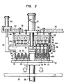
- FIG.2 is a vertical cross-sectional view of upper and lower molds;
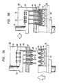
- FIGS. 3A and 3B are perspective views showing ejecting operation;
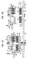
- FIGS. 4A through 4D are cross-sectional views illustrating the manner in which a filter element blank is successively processed by the upper and lower molds;
- FIG. 5 is an enlarged fragmentary cross-sectional view of the filter element blank;
- FIGS. 6A and 6B are cross-sectional views of filter element blanks of different peak heights mounted on the lower mold;
- FIGS. 7A and 7B are cross-sectional views showing the manner in which fins of the upper mold slide when processing a filter element blank of a smaller peak height;
- FIG. 8 is a plan view of a filter element blank cut off from a filter element material sheet;
- FIG. 9 is a perspective view of the filter element blank which has been creased or corrugated along arcuate lines;
- FIG. 10 is a perspective view of the filter element blank with its opposite edges brought together into a ring shape; and
- FIG. 11 is a plan view of the ring-shaped filter element blank.
- As shown in FIG. 8, a flat filter element blank 101 of a sectorial shape is cut off from a filter element material sheet (not shown). The sector-shaped blank 101 is then creased or corrugated along spaced arcuate lines b -bʹ, c - cʹ, ... j - jʹ of the sectorial shape to form alternate peak and valley folds successively arranged from one end a - aʹ to the other end k - kʹ as shown in FIG. 9. The blank 101 is thereafter curved in its entirety with the end a - aʹ located inside and the end k - kʹ outside until
opposite ends peak folds 12 andvalley folds 14 which are angularly bent at 12ʹ, 14ʹ in several circumferentially spaced locations. - FIG. 1 shows successive steps of shaping the ring-shaped filter element blank 10 into a filter element. The
opposite ends - The ring-shaped blank 10 is shaped by a mold assembly comprising a
lower mold 16 and anupper mold 28. Thelower mold 16 is of a circular shape having a plurality of as many concentric projections orfins 18 as the number of thepeak folds 12 of the ring-shaped blank 10, and a plurality of valleys orgrooves 20 defined between thefins 18. Thelower mold 16 is carried by apallet 22 placed on aconveyor 24. The ring-shaped blank 10 is mounted on thelower mold 16 in a position (A) in FIG. 1. - The ring-shaped blank 10 mounted on the
lower mold 16 is fed by theconveyor 24 from the position (A) to a shaping station in a position (B). Alifter cylinder 26 is disposed in the shaping station for elevating thelower mold 16. Theupper mold 28 is located in the shaping station above thelower mold 16. Thelower mold 16 lifted by thelifter cylinder 26 is pressed against theupper mold 28. - As shown in FIG. 2, the
upper mold 28 includes a heat-insulatingsupport plate 32 fixed to astationary base 30, and aheating plate 34 attached to thesupport plate 32 and accommodatingheaters 36 therein. Adisc suspension ring 38 is also attached to thesupport plate 32 with theheating plate 34 therebetween, and a circular plate ordisc 40 is fixed to the lower end of thedisc suspension ring 38. - The
disc 40 has a plurality of as manyconcentric grooves 42 as the number of thefins 18 of thelower mold 16, thegrooves 42 being defined in a lower surface of thedisc 40 in vertical alignment with thefins 18 of thelower mold 16. Thegrooves 42 can receive therespective fins 18 on which thepeak folds 12 of the ring-shaped blank 10 are mounted, when thelower mold 16 is pressed upwardly against thedisc 40. Thedisc 40 also has a plurality ofarcuate slits 44 defined along concentric circular lines in thedisc 40 between thegrooves 42. Each circular slit group has seven circumferentially spacedarcuate slits 44 in the illustrated embodiment. A plurality of arcuate (as viewed from below the upper mold 28) projections orfins 46 are slidably inserted respectively in theslits 44 in vertical alignment with thegrooves 20 of thelower mold 16. Thefins 46 haveupper ends 46a fixed to a finheight adjustment plate 48 disposed within thering 38 and below theheating plate 34. As shown in FIGS. 3A and 3B, there are sevenarcuate fins 46 in each circular fin group which are circumferentially spaced along a concentric circular line and disposed incorresponding slits 44. - The fin
height adjustment plate 48 is normally urged to move downwardly bysprings 50 disposed between the finheight adjustment plate 48 and theheating plate 34. The finheight adjustment plate 48 is centrally secured to the lower threaded end of apiston rod 54 of aheight adjustment cylinder 52 fixedly mounted on the upper surface of thesupport plate 32. Dependent on the height of the folds of the ring-shaped blank 10 mounted on thelower mold 16, the extent to which thefins 46 project from the lower ends of theslits 44 can be adjusted by vertically moving thepiston rod 54. - An ejector or
knockout ring 56 is loosely fitted over thedisc 40 and has a plurality of integral ejectors orknockouts 58 disposed in circumferentially spaced positions and extending radially toward the center of thedisc 40. As shown in FIGS. 2 and 3B, eachknockout 58 is of a narrow member having a plurality offins 60 which are identical in cross section to thefins 46 and a plurality ofgrooves 62 which are positioned between thefins 60 and identical in shape to thegrooves 42 of thedisc 40. Theknockout 58 has anupper end 58a held against the finheight adjustment plate 48. Thefins 60 of theknockouts 58 are arcuate in shape and are slidably inserted respectively in slits defined circumferentially between thefins 46. In the illustrated embodiment, there are sevenknockouts 58 which are integrally coupled by thering 56. Thefins 60 are omitted from illustration in FIGS. 3A and 3B. Theknockout ring 56 is coupled to acoupling 68 on the distal end of apiston rod 66 of aknockout cylinder 64 mounted on the upper surface of thebase 30. When thelifter cylinder 26 is operated to lower thelower mold 16 away from theupper mold 28, theknockout cylinder 64 is also actuated to lower theknockouts 58 in unison with thelower mold 16. - FIG. 3A shows the
knockouts 58 retracted upwardly into thedisc 40. FIG. 3B illustrates theknockouts 58 lowered out of thedisc 40 to eject the shaped filter element when thelower mold 16 is moved downwardly away from theupper mold 28. - A process of successively shaping the ring-shaped blank 10 in the shaping station with the upper and
lower molds lower mold 16 carried on thepallet 22, and then delivered by theconveyor 24 to a position directly below theupper mold 28, as shown in FIG. 4A. At this time, thefins 46 of theupper mold 28 are adjusted in height by theheight adjustment cylinder 52 to match the height of the folds of the ring-shaped blank 10. Theupper surfaces 58a of theknockouts 58 are held in contact with the lower surface of the finheight adjustment plate 48. Thegrooves 42 of thedisc 40 and thegrooves 62 of theknockouts 58 are registered with each other, and the tip ends 46 of thefins 46 and the tip ends of thefins 60 of theknockouts 58 are aligned with each other. Thedisc 40, thefins 46, and theknockouts 58 are bodily heated by theheating plate 34 up to a temperature for heat-setting the ring-shaped blank 10. - Then, the
lifter cylinder 26 is elevated to press thelower mold 16 against theupper mold 28 as shown in FIG. 4B. The tip ends of thefins 18 of thelower mold 16 on which the peak folds 12 of the blank 10 are fitted respectively into theconcentic grooves 42 of thedisc 40, and thefins 46 of theupper mold 28 are inserted respectively into the valleys orgrooves 14 of the blank 10, with the tip ends of thefins 46 pressing the bottoms of thevalleys 14. Likewise, the peak folds 12 of the blank 10 are forced respectively into thegrooves 62 of theknockouts 58 by thefins 18, and thefins 60 of theknockouts 58 are pressed against the bottoms of thevalleys 14 of the blank 10. A shown in FIG. 5 at an enlarged scale, the filter element blank 10 is composed of a laminated structure comprising an upperdense layer 76, anintermediate layer 78, and a lowercoarse layer 80. Thedense layer 76 has a fiber structure which is most closely massed and intertwined, and hence is most resistant to deformation. Therefore, the filter element blank 10 has a density gradient in its axial direction. Since thedense layer 76 is positioned in direct contact with theheated disc 40, thefins 46, and thefins 60, it is well heated to shape or heat-set the peak folds 12 and the valley folds 14 to true concentric configuration while rectifying the angularly bent edges 12ʹ, 14ʹ to smooth round surfaces. - After the blank 10 has been heated for a prescribed period of time, e.g., about 5 seconds, under pressure between the
upper mold 28 and thelower mold 16, thelifter cylinder 26 is lowered to displace thelower mold 16 away from theupper mold 28, as illustrated in FIG. 4C. At the same time, theknockout cylinder 64 is operated to lower theknockouts 58 in unison with thelower mold 16. The shapedfilter element 10A on thelower mold 16 is thus ejected by theknockouts 58 and separated from theupper mold 28 without sticking thereto. - When the
lower mold 16 is placed on theconveyor 24, theknockouts 58 are lifted back into thedisc 40, and thelower mold 16 with thefilter element 10A thereon is delivered to a next cooling station, as shown in FIG. 4D. - There are filter element blanks of different types that are to be shaped into filter elements. They can roughly be classified into those having different numbers of folds, and those having different heights of folds.
- Filter element blanks of different numbers of folds can be shaped by one set of upper and lower molds insofar as the upper and lower molds have a maximum number of fins.
- As illustrated in FIGS. 6A and 6B, ring-shaped
filter element blanks upper mold 28 can process such blanks of different fold heights by adjusting the projection of thefins 46 with theheight adjustment cylinder 52. - The
fins 46 of theupper mold 28 are also automatically adjustable in height to accommodate a certain range of fold heights. More specifically, as shown in FIG. 7A, thefins 46 are previously adjusted in height to match the fold height of a ring-shaped filter element blank. After the blank has been shaped, another ring-shaped blank 10 of a smaller fold height is mounted on thelower mold 16. Thelower mold 16 is lifted and pressed against theupper mold 28 with the blank 10 interposed therebetween. The finheight adjustment plate 48 is normally biased by thespring 50 to move downwardly. However, when the blank 10 is force against theupper mold 28, thefins 46 are displaced upwardly by the blank 10 while compressing thesprings 50, so that the peak folds 12 and the valley folds 14 of the blank 10 can neatly be shaped with heat by thefins grooves 62 of theknockouts 58 out of contact with the peak folds 12 of the blank 10. Therefore, those areas of the peak folds 12 which are out of contact with theknockouts 58 are not shaped under pressure. However, such non-contact areas of the peak folds 12 are limited to small proportion and do not adversely affect the shaping of the entire blank 10. Consequently, the mold assembly can shape ring-shaped filter element blanks of different fold heights without operating the height adjustment cylinder 52 (FIG. 2) as long as such different fold heights are within the range in which the finheight adjustment plate 48 is vertically slidable against the resiliency of thesprings 50. - The shaped
filter element 10A is delivered from the shaping station at (B) in FIG. 1 to the cooling station at (C) in FIG. 1. The cooling station has anair supply duct 72 with anair blower 70 disposed in its upper end, and adischarge duct 74 located below theair supply duct 72 with theconveyor 24 therebetween. Thefilter element 10A that has been heat-set in the shaping station is cooled in the cooling station by cooling air supplied downwardly from theair blower 70 through theair supply duct 72 into theair discharge duct 74. - While the
upper mold 28 is shown as being heated, and thelower mold 16 is shown as being pressable against theupper mold 28, thelower mold 16 may instead be heated, and theupper mold 28 may instead be pressed against thelower mold 16. The filter element blank may be of a single layer rather than a multiple-layer structure.
Claims (17)
- A method of forming a filter element, comprising the steps of; providing a corrugated filter element blank (10) which is at least partly curved and has radially alternate peak (12) and valley (14) folds; placing the curved blank (10) on a first mold (16) having as many concentric projections (18) as the number of the peak folds (12) of the curved blank (10) and as many curved grooves (20) as the number of the valley folds (14) of said curved blank (10), with the peak folds (12) fitted respectively over the projections (18) and the valley folds (14) fitted respectively in the grooves (20); preheating a second mold (28), the second mold (28) having projections (46) lying along concentric lines for fitting respectively in the grooves (20) of the first mold (16) with the valley folds (14) received therein, and concentric grooves (42) for receiving respectively the projections (18) of the first mold (16) with the peak folds (12) fitted thereover; pressing the curved blank (10) between the first (16) and second (28) molds; heating the curved blank (10) while it is being pressed between said first (16) and second (28) molds, thereby to form a filter element which is at least partly curved and has concentric peak and valley folds; separating the said curved filter element from the second mold; and cooling the said curved filter element.
- A method according to claim 1 wherein the corrugated filter element blank (10) is ring-shaped.
- A method according to claim 1 or claim 2, wherein the first (16) and second (28) molds comprise lower and upper molds, respectively, the lower mold being movable toward and pressable against the upper mold for pressing the ring-shaped blank (10) between the upper and lower molds.
- A method according to claim 3, wherein after being separated from the second mold (28) the first mold (16) is delivered with the circular filter element thereon for cooling.
- A method according to any preceding claim, wherein during pressing of the blank, the valley folds (12) of the curved blank (10) are pressed by the projections (46) of the second mold (28) within the grooves (20) of the first mold, and the peak folds (12) of the curved blank (10) are pressed by the projections (18) of the first mold (16) within the grooves (42) of the second mold (28).
- A method according to any preceding claim, wherein the curved blank (10) has a density gradient in an axial direction thereof.
- A method according to any preceding claim, wherein the curved blank is formed from a filter element blank (10) of a sectorial shape with the peak (12) and valley (14) folds extending along arcuate lines of the sectorial shape.
- An apparatus for forming a filter element, comprising: a first mold (16) having concentric projections (18) and concentric grooves (20), the projections (18) and grooves (20) being alternately arranged; a second mold (28) having projections (46) lying along concentric lines and positioned in alignment with grooves (20) of the first mold, respectively, and concentric grooves (42) positioned in alignment with projections (18) of the first mold, respectively, the projections (46) and grooves (42) of the second mold (28) being alternately arranged; means (26) for moving the first (16) and second (28) molds relatively to each other to bring the projections (18) of the first mold (16) into and out of grooves (42) of the second mold (28) and also to bring the projections (46) of the second mold (28) into and out of the grooves (20) of the first mold (16); heater means (34,36) for heating one of the first (16) and second (28) molds, and an ejector mechanism (56,58) operable to separate from the heated mold a filter element formed by heat pressing a blank (10) between the two molds.
- Apparatus according to claim 8, wherein the first (16) and second (28) molds comprise lower and upper molds, respectively, the upper mold being positioned upwardly of the lower mold.
- Apparatus according to claim 8, wherein the heater means comprises an electric heater (36) disposed in the second mold (28) for heating the projections (46) and the grooves (42) of the second mold.
- Apparatus according to claim 8, wherein the second mold (28) includes the ejector mechanism (56,58) which is movable toward the projections (18) and the grooves (20) of the first mold (16) when the first (16) and second (28) molds are moved away from each other by the moving means (26) to bring the projections (18) of the first mold (16) out of the grooves (42) of the second mold (28) and also to bring the projections (42) of the second mold (28) out of the grooves (20) of the first mold (16).
- Apparatus according to claim 11, wherein the projections (42) of the second mold (28) have arcuate shapes, respectively, which are circumferentially spaced along each of the said concentric lines, the ejector mechanism (56,58) being disposed between the spaced arcuate projections (46) of the second mold (28) along the concentric lines.
- Apparatus according to claim 12, wherein the ejector mechanism (56,58) has grooves (62) defined in one end thereof for receiving the projections (18) of the first mold (16) respectively therein and projections (60) on the said one end for engaging in the grooves (20) of the first mold, respectively.
- Apparatus according to claim 13, wherein the projections (18) of the first mold, the projections (46) of the second mold, and the projections (60) of the ejector mechanism (56,58) are in the form of fins.
- Apparatus according to claim 8, wherein the second mold (28) has first and second (32) plates, the first plate having the grooves (42) of the second mold (44) and slits aligned with said second projections, respectively, and lying along concentric lines, the projections (42) of the second mold being disposed respectively in the slits (44), the projections of the second mold having one ends projecting from the first plate toward the first mold and opposite ends projecting from the first plate away from the first mold (16) and fixed to the second plate.
- Apparatus according to claim 15, wherein the projections (42) of the second mold are movably disposed in the slits (44), respectively, further including adjustment means (52,54) coupled to the second plate (32) for moving the projections (42) of the second mold through the slits (44) to adjust the extent to which the said one ends of the projections (46) of the second mold project from the first plate toward the first mold (16).
- Apparatus according to claim 8, further including adjustment means for adjusting the extent to which the projections (46) of the second mold (28) project toward the first mold (16).
Priority Applications (1)
| Application Number | Priority Date | Filing Date | Title |
|---|---|---|---|
| AT87306937T ATE96686T1 (en) | 1986-08-20 | 1987-08-05 | METHOD AND APPARATUS FOR FORMING A FILTER ELEMENT. |
Applications Claiming Priority (2)
| Application Number | Priority Date | Filing Date | Title |
|---|---|---|---|
| JP194489/86 | 1986-08-20 | ||
| JP61194489A JPH0785769B2 (en) | 1986-08-20 | 1986-08-20 | ▲ Ro ▼ Overmolding method for over-element |
Publications (2)
| Publication Number | Publication Date |
|---|---|
| EP0256772A1 EP0256772A1 (en) | 1988-02-24 |
| EP0256772B1 true EP0256772B1 (en) | 1993-11-03 |
Family
ID=16325374
Family Applications (1)
| Application Number | Title | Priority Date | Filing Date |
|---|---|---|---|
| EP87306937A Expired - Lifetime EP0256772B1 (en) | 1986-08-20 | 1987-08-05 | Method of and apparatus for forming filter element |
Country Status (13)
| Country | Link |
|---|---|
| US (1) | US4834700A (en) |
| EP (1) | EP0256772B1 (en) |
| JP (1) | JPH0785769B2 (en) |
| KR (1) | KR900005521B1 (en) |
| CN (1) | CN1009161B (en) |
| AT (1) | ATE96686T1 (en) |
| AU (1) | AU575751B2 (en) |
| CA (1) | CA1262515A (en) |
| DE (1) | DE3788021T2 (en) |
| ES (1) | ES2044938T3 (en) |
| MY (1) | MY101330A (en) |
| PH (1) | PH24809A (en) |
| PT (1) | PT85554B (en) |
Families Citing this family (19)
| Publication number | Priority date | Publication date | Assignee | Title |
|---|---|---|---|---|
| EP0523986A1 (en) * | 1991-07-17 | 1993-01-20 | Universal Filtration (Proprietary) Limited | Apparatus for manufacturing a filter element |
| US5630940A (en) * | 1993-04-01 | 1997-05-20 | Minnesota Mining And Manufacturing Company | Filter device for the filtration of fluids |
| AU5719896A (en) * | 1995-04-27 | 1996-11-18 | Avecor Cardiovascular Inc. | Method of manufacturing a fluid filter |
| DE19700433C2 (en) * | 1997-01-10 | 2002-11-28 | Preh Elektro Feinmechanik | Airbag and a method and an apparatus for folding the airbag for an occupant restraint system |
| JP3918358B2 (en) * | 1999-04-22 | 2007-05-23 | 株式会社デンソー | Manufacturing method of filter element |
| NL1011915C2 (en) | 1999-04-28 | 2000-10-31 | Wiltoe Innovatie B V | Ice cube maker and insert for an ice cube tray thereof. |
| US20030024140A1 (en) * | 2001-07-07 | 2003-02-06 | Thompson Owen R. | Filter pleating machine |
| US20070151920A1 (en) * | 2005-12-06 | 2007-07-05 | Kay Ronald J | System and method of micromolded filtration microstructure and devices |
| JP4699340B2 (en) * | 2006-11-16 | 2011-06-08 | 日東電工株式会社 | Filter unit |
| US8545589B2 (en) * | 2007-06-26 | 2013-10-01 | Donaldson Company, Inc. | Filtration media pack, filter element, and methods |
| JP5055140B2 (en) * | 2008-01-10 | 2012-10-24 | ユニ・チャーム株式会社 | Sheet shaping method |
| KR20100086753A (en) * | 2009-01-23 | 2010-08-02 | 삼성전자주식회사 | Oven range |
| NL2002676C2 (en) * | 2009-03-26 | 2010-09-28 | Vmi Holland Bv | FOLDING DEVICE AND COMPOSITION FOR MAKING A FOLD IN A FOLDABLE PACKAGE MATERIAL OR PACKAGING MATERIAL. |
| CN104567336A (en) * | 2015-01-15 | 2015-04-29 | 中国建筑材料科学研究总院 | Filter pressing and drying die |
| CN106626533A (en) * | 2016-12-13 | 2017-05-10 | 柳州通为机械有限公司 | Automotive filter element mould |
| US11433332B2 (en) * | 2018-11-05 | 2022-09-06 | Hollingsworth & Vose Company | Filter media with irregular structure |
| US11420143B2 (en) | 2018-11-05 | 2022-08-23 | Hollingsworth & Vose Company | Filter media with irregular structure and/or reversibly stretchable layers |
| CN109720011B (en) * | 2018-12-18 | 2020-10-30 | 天长市天翔集团有限公司 | Corrugated container board forming device |
| CN111038002A (en) * | 2019-12-27 | 2020-04-21 | 江苏元泰智能科技股份有限公司 | Filter paper wave forming device and forming method |
Family Cites Families (14)
| Publication number | Priority date | Publication date | Assignee | Title |
|---|---|---|---|---|
| US1989015A (en) * | 1932-06-10 | 1935-01-22 | Philadelphia Storage Battery | Method of making sound reproducing diaphragms |
| US2531555A (en) * | 1946-05-03 | 1950-11-28 | United Shoe Machinery Corp | Article-forming system |
| FR2158667A5 (en) * | 1971-10-28 | 1973-06-15 | Maillan Bernard | |
| US4098177A (en) * | 1976-05-13 | 1978-07-04 | Brown Company | Filter paper cup for a percolator and process for making the same |
| US4246223A (en) * | 1978-11-20 | 1981-01-20 | Peerless Machine And Tool Corporation | Method and apparatus of making a compartment tray |
| SU1022765A1 (en) * | 1980-12-10 | 1983-06-15 | Предприятие П/Я А-1697 | Device for manufacturing tape with corrugations arranged in cross-board order |
| US4430223A (en) * | 1981-02-25 | 1984-02-07 | Nippondenso Co., Ltd. | Filter element for filtering fluid and method of producing same |
| AU540096B2 (en) * | 1982-08-04 | 1984-11-01 | Nippondenso Co. Ltd. | Filter device and manufacturing method |
| JPS5936515A (en) * | 1982-08-20 | 1984-02-28 | Nippon Denso Co Ltd | Production of filter element |
| JPS60225615A (en) * | 1984-04-24 | 1985-11-09 | Nippon Denso Co Ltd | Method and apparatus for rounding molding of ring shaped element |
| JPS60174218A (en) * | 1984-02-20 | 1985-09-07 | Nippon Denso Co Ltd | Method and device for bending annular element |
| EP0200798B1 (en) * | 1985-05-07 | 1989-01-25 | Nippondenso Co., Ltd. | Method for making a curved, corrugated article and apparatus therefor |
| JPS61161113A (en) * | 1985-01-07 | 1986-07-21 | Nippon Denso Co Ltd | Filter for fluid |
| JPS6237143A (en) * | 1985-08-12 | 1987-02-18 | 株式会社デンソー | Method and device for molding filter element |
-
1986
- 1986-08-20 JP JP61194489A patent/JPH0785769B2/en not_active Expired - Lifetime
-
1987
- 1987-07-30 CA CA000543477A patent/CA1262515A/en not_active Expired
- 1987-07-31 US US07/080,009 patent/US4834700A/en not_active Expired - Lifetime
- 1987-08-05 AT AT87306937T patent/ATE96686T1/en not_active IP Right Cessation
- 1987-08-05 EP EP87306937A patent/EP0256772B1/en not_active Expired - Lifetime
- 1987-08-05 ES ES87306937T patent/ES2044938T3/en not_active Expired - Lifetime
- 1987-08-05 DE DE87306937T patent/DE3788021T2/en not_active Expired - Fee Related
- 1987-08-10 MY MYPI87001278A patent/MY101330A/en unknown
- 1987-08-11 PH PH35655A patent/PH24809A/en unknown
- 1987-08-13 AU AU76846/87A patent/AU575751B2/en not_active Ceased
- 1987-08-17 KR KR1019870008984A patent/KR900005521B1/en not_active IP Right Cessation
- 1987-08-18 CN CN87105639A patent/CN1009161B/en not_active Expired
- 1987-08-19 PT PT85554A patent/PT85554B/en not_active IP Right Cessation
Also Published As
| Publication number | Publication date |
|---|---|
| CN87105639A (en) | 1988-03-16 |
| DE3788021D1 (en) | 1993-12-09 |
| AU575751B2 (en) | 1988-08-04 |
| MY101330A (en) | 1991-09-05 |
| KR900005521B1 (en) | 1990-07-31 |
| PH24809A (en) | 1990-10-30 |
| EP0256772A1 (en) | 1988-02-24 |
| ES2044938T3 (en) | 1994-01-16 |
| ATE96686T1 (en) | 1993-11-15 |
| US4834700A (en) | 1989-05-30 |
| CN1009161B (en) | 1990-08-15 |
| CA1262515A (en) | 1989-10-31 |
| JPH0785769B2 (en) | 1995-09-20 |
| AU7684687A (en) | 1988-02-25 |
| PT85554A (en) | 1988-08-17 |
| KR880002562A (en) | 1988-05-09 |
| JPS6349219A (en) | 1988-03-02 |
| PT85554B (en) | 1994-03-31 |
| DE3788021T2 (en) | 1994-03-03 |
Similar Documents
| Publication | Publication Date | Title |
|---|---|---|
| EP0256772B1 (en) | Method of and apparatus for forming filter element | |
| US20240266930A1 (en) | Apparatus for manufacturing laminated core with heating adhesion | |
| US4304621A (en) | Apparatus for the manufacture of a jacket for a flexible disk for data recording | |
| US2158312A (en) | Machine for making a barrel | |
| JPS58185240A (en) | System manufacturing paper product from paper roll | |
| US3183291A (en) | Rim shaping apparatus for plastic containers and method | |
| JPH02290700A (en) | Thermoforming press apparatus for disk pad | |
| KR960004240A (en) | Flexible press | |
| EP0246838A2 (en) | Mould assembly for use in the manufacture of a shadow mask for a colour cathode ray tube | |
| US4713046A (en) | Circular machine for automatic manufacturing of display boxes | |
| JPH0681453B2 (en) | Coil forming equipment | |
| EP0073416A2 (en) | Methods and means for forming containers from heat shrinkable oriented foam plastic sheet material | |
| KR102291148B1 (en) | Forming apparatus of powder forming article | |
| EP0266316A2 (en) | Method for the automated manufacture of laminated plastics products | |
| KR950009967B1 (en) | Method for manufacturing paper cup | |
| TH7793A (en) | Methods and equipment for filter forming | |
| TH2376B (en) | Methods and equipment for filter forming | |
| EP0153742A1 (en) | An apparatus for manufacturing a jacket case for disc | |
| EP0200798A1 (en) | Method for making a curved, corrugated article and apparatus therefor | |
| WO2004078430A2 (en) | Die curl assembly | |
| US20240266929A1 (en) | Apparatus for manufacturing laminated core capable of adjusting height of back pressure unit automatically | |
| KR100412315B1 (en) | Apparatus forming pleated baking case | |
| CN118682004A (en) | Stamping die easy to demould | |
| SU1173455A1 (en) | Production line for group stacks of monolith ceramic capacitors | |
| US2936485A (en) | Apparatus for making ring closures |
Legal Events
| Date | Code | Title | Description |
|---|---|---|---|
| PUAI | Public reference made under article 153(3) epc to a published international application that has entered the european phase |
Free format text: ORIGINAL CODE: 0009012 |
|
| AK | Designated contracting states |
Kind code of ref document: A1 Designated state(s): AT DE ES FR GB IT |
|
| 17P | Request for examination filed |
Effective date: 19880317 |
|
| 17Q | First examination report despatched |
Effective date: 19900116 |
|
| GRAA | (expected) grant |
Free format text: ORIGINAL CODE: 0009210 |
|
| AK | Designated contracting states |
Kind code of ref document: B1 Designated state(s): AT DE ES FR GB IT |
|
| REF | Corresponds to: |
Ref document number: 96686 Country of ref document: AT Date of ref document: 19931115 Kind code of ref document: T |
|
| RIN1 | Information on inventor provided before grant (corrected) |
Inventor name: IWASE, TAKATOSHI Inventor name: ITO, YUJI Inventor name: MOCHIZUKI, IKUO Inventor name: MIYAGAWA, YOSHIAKI Inventor name: HANAI, MINEO Inventor name: KONDO, NAOHIKO |
|
| REF | Corresponds to: |
Ref document number: 3788021 Country of ref document: DE Date of ref document: 19931209 |
|
| REG | Reference to a national code |
Ref country code: ES Ref legal event code: FG2A Ref document number: 2044938 Country of ref document: ES Kind code of ref document: T3 |
|
| ITF | It: translation for a ep patent filed | ||
| ET | Fr: translation filed | ||
| REG | Reference to a national code |
Ref country code: GB Ref legal event code: 746 Effective date: 19940616 |
|
| PLBE | No opposition filed within time limit |
Free format text: ORIGINAL CODE: 0009261 |
|
| STAA | Information on the status of an ep patent application or granted ep patent |
Free format text: STATUS: NO OPPOSITION FILED WITHIN TIME LIMIT |
|
| REG | Reference to a national code |
Ref country code: FR Ref legal event code: DL |
|
| 26N | No opposition filed | ||
| REG | Reference to a national code |
Ref country code: GB Ref legal event code: IF02 |
|
| PGFP | Annual fee paid to national office [announced via postgrant information from national office to epo] |
Ref country code: GB Payment date: 20030730 Year of fee payment: 17 |
|
| PGFP | Annual fee paid to national office [announced via postgrant information from national office to epo] |
Ref country code: FR Payment date: 20030808 Year of fee payment: 17 |
|
| PGFP | Annual fee paid to national office [announced via postgrant information from national office to epo] |
Ref country code: AT Payment date: 20030813 Year of fee payment: 17 |
|
| PGFP | Annual fee paid to national office [announced via postgrant information from national office to epo] |
Ref country code: DE Payment date: 20030814 Year of fee payment: 17 |
|
| PGFP | Annual fee paid to national office [announced via postgrant information from national office to epo] |
Ref country code: ES Payment date: 20030926 Year of fee payment: 17 |
|
| PG25 | Lapsed in a contracting state [announced via postgrant information from national office to epo] |
Ref country code: GB Free format text: LAPSE BECAUSE OF NON-PAYMENT OF DUE FEES Effective date: 20040805 Ref country code: AT Free format text: LAPSE BECAUSE OF NON-PAYMENT OF DUE FEES Effective date: 20040805 |
|
| PG25 | Lapsed in a contracting state [announced via postgrant information from national office to epo] |
Ref country code: ES Free format text: LAPSE BECAUSE OF NON-PAYMENT OF DUE FEES Effective date: 20040806 |
|
| PG25 | Lapsed in a contracting state [announced via postgrant information from national office to epo] |
Ref country code: DE Free format text: LAPSE BECAUSE OF NON-PAYMENT OF DUE FEES Effective date: 20050301 |
|
| GBPC | Gb: european patent ceased through non-payment of renewal fee |
Effective date: 20040805 |
|
| PG25 | Lapsed in a contracting state [announced via postgrant information from national office to epo] |
Ref country code: FR Free format text: LAPSE BECAUSE OF NON-PAYMENT OF DUE FEES Effective date: 20050429 |
|
| REG | Reference to a national code |
Ref country code: FR Ref legal event code: ST |
|
| PG25 | Lapsed in a contracting state [announced via postgrant information from national office to epo] |
Ref country code: IT Free format text: LAPSE BECAUSE OF NON-PAYMENT OF DUE FEES;WARNING: LAPSES OF ITALIAN PATENTS WITH EFFECTIVE DATE BEFORE 2007 MAY HAVE OCCURRED AT ANY TIME BEFORE 2007. THE CORRECT EFFECTIVE DATE MAY BE DIFFERENT FROM THE ONE RECORDED. Effective date: 20050805 |
|
| REG | Reference to a national code |
Ref country code: ES Ref legal event code: FD2A Effective date: 20040806 |