EP0255359A2 - A helically fabricated flexible hose - Google Patents
A helically fabricated flexible hose Download PDFInfo
- Publication number
- EP0255359A2 EP0255359A2 EP87306705A EP87306705A EP0255359A2 EP 0255359 A2 EP0255359 A2 EP 0255359A2 EP 87306705 A EP87306705 A EP 87306705A EP 87306705 A EP87306705 A EP 87306705A EP 0255359 A2 EP0255359 A2 EP 0255359A2
- Authority
- EP
- European Patent Office
- Prior art keywords
- helical
- support members
- plastics
- disposed
- strip
- Prior art date
- Legal status (The legal status is an assumption and is not a legal conclusion. Google has not performed a legal analysis and makes no representation as to the accuracy of the status listed.)
- Granted
Links
Images

Classifications
-
- F—MECHANICAL ENGINEERING; LIGHTING; HEATING; WEAPONS; BLASTING
- F16—ENGINEERING ELEMENTS AND UNITS; GENERAL MEASURES FOR PRODUCING AND MAINTAINING EFFECTIVE FUNCTIONING OF MACHINES OR INSTALLATIONS; THERMAL INSULATION IN GENERAL
- F16L—PIPES; JOINTS OR FITTINGS FOR PIPES; SUPPORTS FOR PIPES, CABLES OR PROTECTIVE TUBING; MEANS FOR THERMAL INSULATION IN GENERAL
- F16L11/00—Hoses, i.e. flexible pipes
- F16L11/04—Hoses, i.e. flexible pipes made of rubber or flexible plastics
- F16L11/11—Hoses, i.e. flexible pipes made of rubber or flexible plastics with corrugated wall
- F16L11/118—Hoses, i.e. flexible pipes made of rubber or flexible plastics with corrugated wall having arrangements for particular purposes, e.g. electrically conducting
- F16L11/1185—Hoses, i.e. flexible pipes made of rubber or flexible plastics with corrugated wall having arrangements for particular purposes, e.g. electrically conducting electrically conducting
-
- A—HUMAN NECESSITIES
- A47—FURNITURE; DOMESTIC ARTICLES OR APPLIANCES; COFFEE MILLS; SPICE MILLS; SUCTION CLEANERS IN GENERAL
- A47L—DOMESTIC WASHING OR CLEANING; SUCTION CLEANERS IN GENERAL
- A47L9/00—Details or accessories of suction cleaners, e.g. mechanical means for controlling the suction or for effecting pulsating action; Storing devices specially adapted to suction cleaners or parts thereof; Carrying-vehicles specially adapted for suction cleaners
- A47L9/24—Hoses or pipes; Hose or pipe couplings
Definitions
- U.S. Patent 4,224,463 and its corresponding U.K. Patent 2,034,859 describe a helically fabricated flexible hose wherein first and second parallel helical wires are disposed in double lead fashion with successive convolutions alternating.
- An inner plastics strip is wrapped helically about the wires and is wider than the double lead of each wire, so that it has forward and rearward edge portions overlapping over convolutions of the first of the wires.
- An outer plastics strip is wrapped helically about the inner plastics strip and is wider than the double lead of each wire with forward and rearward edge portions overlapping over convolutions of the second of the wires.
- a plastics dielectric coating is disposed about each wire and a plurality of reinforcing cords are located about the inner strip and inside the outer strip, the plastics coatings and the two strips all being bonded together.
- a helically fabricated flexible hose having at least two parallel helical support members disposed in multiple lead fashion with each being axially spaced from the other or others.
- An inner plastics strip is wrapped helically about the support members and has forward and rearward edge portions overlapping the convolutions of one of the support members.
- An outer plastics strip is wrapped helically about the inner plastics strip and has forward and rearward edge portions overlapping the convolutions of another of the support members.
- At least one pair of helical electrical conductors is disposed on opposite sides of one of the helical support members and slidably positioned between the inner and outer plastics strips.
- the helical conductors are preferably stranded, for example of a plurality of copper strands disposed within a dielectric plastics coating to provide further electrical insulation in addition to the non-conductive inner and outer plastics strips. These plastics dielectric coatings of the helical conductors are not bonded to the inner and outer plastics strips so that they may slide between them.
- each helical support member flexes independently of the other, and the structure therefore possesses exceptional flexibility allowing it to drape readily with close bend radius, all of which is important, as stated above, for vacuum cleaner hoses.
- Each of the helical conductors flexes with the helical support member with which it is associated, and is protected by its helical configuration from longitudinal stresses and by its positioning adjacent to the helical support member from kinking and excessive flexing. Because they are able to slide in the space they occupy between the inner and outer plastics strips, the helical conductors are not subjected to the stretching and tearing forces which would be transferred from the inner and outer strips if they were bonded to the helical support members.
- the invention is applicable to the hose in which the wires 10 and 11 are not current-carrying, and in such cases the current or currents to be carried from one end of the hose to the other would flow through the one or more pairs of helical conductors which straddle the helical support members 10 and/or 11.
- the helical support members 10 and 11 would be formed of plastics material, for example.
- the inner strip 14 is in the range from 0.014" to 0.020" (approximately 0.35 to 0.5 mm).
- the width of the inner plastics strip is slightly greater than the double lead of the pair of wires 10 and 11.
- the rearward edge of the strip 14 thereby overlies the second wire 11, the central portion of the strip 14 overlies the next adjoining convolution of the first wire 10, and the forward edge of the strip 14 overlies the following convolution of the second wire 11.
- the rearward edge of the strip 14 is in direct contact with and bonds to the coating 13 of wire 11, and the forward edge of the strip 14 is in direct contact with and bonds to the rearward edge of the strip 14 on the next convolution of that same wire 11.
- a pair of helical conductors 16 and 17 is formed as an integral part of the hose by being sandwiched between the inner strip 14 and an outer strip 20 described below, on opposite sides of coated wire 10.
- the helical conductors 16 and 17 are preferably stranded copper conductors enclosed within a dielectric sheath.
- Such stranded copper conductors would preferably include relatively small numbers of copper strands, for example 5 to 10 strands of 30-gauge, as shown in Fig. 5.
- Stranded conductors have been found to be less costly than braided conductors and less susceptible to breaking than solid conductors, although these forms of conductors could also be used.
- the dielectric sheaths surrounding the stranded copper conductors may be eliminated because of the positioning of the helical conductors 16 and 17 between the inner and outer dielectric plastics strips 14 and 20. Each dielectric sheath is not bonded to the strips 14 and 20 so that it may slide with respect to those strips. Bonding is prevented by simply not applying either heat or solvent to the dielectric sheaths of the helical conductors 16 and 17.
- the hose construction and the manner of forming it are generally as described above for the first preferred embodiment, except for the inclusion of a third helical support member.
- the three helical support members 30, 31 and 32 have a greater helical pitch than their two counterparts in the first embodiment, for example about 0.450" (approximately 11 mm), and may be conductive or non-conductive; if conductive, they are preferably coated with concentric layers of vinyl plastics 33, 34 and 35, respectively.
- a plurality of longitudinal reinforcing cords 37 are next applied, as in the first embodiment. Pairs of helical conductors 38 and 39, 40 and 41, 42 and 43 are then wrapped helically about the partially-formed hose structure so as to straddle the helical support members 30, 31 and 32, respectively. Depending upon the end use of the hose, one or two of the helical conductor pairs 38 and 39, 40 and 41, 42 and 43 may be replaced with helical reinforcing cords.
- the last element applied is an outer plastics strip 44 which overlaps itself over the second helical support member 31, and has its central portion overlying the first and third helical support members 30 and 32.
- this second embodiment in which the helical support members 30, 31 and 32 are conductive, they can provide positive, negative and ground (earth) leads for electrical apparatus at both ends of the hose.
- the several variations in construction referred to in the description of the first embodiment may also be made in this second embodiment.
- a current-carrying hose construction is provided which is of maximum versatility, flexibility, abrasion resistance, optimum longitudinal and radial strength, and minimal wire weight and voltage resistance.
Landscapes
- Engineering & Computer Science (AREA)
- Mechanical Engineering (AREA)
- General Engineering & Computer Science (AREA)
- Rigid Pipes And Flexible Pipes (AREA)
- Supports For Pipes And Cables (AREA)
- Electric Vacuum Cleaner (AREA)
- Pens And Brushes (AREA)
- Paper (AREA)
- Float Valves (AREA)
- Materials For Medical Uses (AREA)
- Resistance Heating (AREA)
- Insulated Conductors (AREA)
- Artificial Filaments (AREA)
- Diaphragms And Bellows (AREA)
Abstract
Description
- This invention related to a helically fabricated flexible hose.
- U.S. Patent 4,224,463 and its corresponding U.K. Patent 2,034,859 describe a helically fabricated flexible hose wherein first and second parallel helical wires are disposed in double lead fashion with successive convolutions alternating. An inner plastics strip is wrapped helically about the wires and is wider than the double lead of each wire, so that it has forward and rearward edge portions overlapping over convolutions of the first of the wires. An outer plastics strip is wrapped helically about the inner plastics strip and is wider than the double lead of each wire with forward and rearward edge portions overlapping over convolutions of the second of the wires. In a preferred form a plastics dielectric coating is disposed about each wire and a plurality of reinforcing cords are located about the inner strip and inside the outer strip, the plastics coatings and the two strips all being bonded together.
- It is characteristic of this structure that each wire convolution is covered by three wall plies, two from one strip and one from the other, with only two wall plies between the wire convolutions, thus imparting markedly better abrasion resistance at the raised convolutions where the greatest wear occurs. Unlike the single lead double-wire hoses proposed previously, the hose described above is of uniform double lead double wire form, so that the amount of wire per unit length of hose is at a minimum. Each wire helix flexes independently of the other and the structure therefore possesses exceptional flexibility allowing it to drape readily with close bend radius, all of which is important for vacuum cleaner hose.
- In accordance with the present invention, there is now provided a helically fabricated flexible hose having at least two parallel helical support members disposed in multiple lead fashion with each being axially spaced from the other or others. An inner plastics strip is wrapped helically about the support members and has forward and rearward edge portions overlapping the convolutions of one of the support members. An outer plastics strip is wrapped helically about the inner plastics strip and has forward and rearward edge portions overlapping the convolutions of another of the support members. At least one pair of helical electrical conductors is disposed on opposite sides of one of the helical support members and slidably positioned between the inner and outer plastics strips. The helical conductors are preferably stranded, for example of a plurality of copper strands disposed within a dielectric plastics coating to provide further electrical insulation in addition to the non-conductive inner and outer plastics strips. These plastics dielectric coatings of the helical conductors are not bonded to the inner and outer plastics strips so that they may slide between them.
- It is characteristic of this structure that each helical support member flexes independently of the other, and the structure therefore possesses exceptional flexibility allowing it to drape readily with close bend radius, all of which is important, as stated above, for vacuum cleaner hoses. Each of the helical conductors flexes with the helical support member with which it is associated, and is protected by its helical configuration from longitudinal stresses and by its positioning adjacent to the helical support member from kinking and excessive flexing. Because they are able to slide in the space they occupy between the inner and outer plastics strips, the helical conductors are not subjected to the stretching and tearing forces which would be transferred from the inner and outer strips if they were bonded to the helical support members.
- The invention will now be described in greater detail by way of example only with reference to the accompanying drawings, in which:
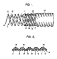
- Fig. 1 is a side elevation, partly broken away, of a dual support wire hose of the invention;
- Fig. 2 is an enlarged section of the wall of the hose of Fig. 1;
- Fig. 3 is a side elevation, partly broken away, of a triple support wire hose of the invention;
- Fig. 4 is an enlarged section of the wall of the hose of Fig. 3; and
- Fig. 5 is an enlarged partial section of Fig. 4.
- All of the various components of the hoses according to the invention are most advantageously assembled on the continuously advancing double belt mandrel of the type described in U.S. Patents 3,155,559 and 4,213,811. Such mandrels are of a diameter ranging from 1.25" to 1.50" (approximately 32 to 38 mm) and form hose of corresponding inside dimensions.
- With reference to the first preferred embodiment of the invention shown in Figs. 1 and 2, the elements initially applied to the mandrel are first and second
helical support members 10 and 11. Each support member is preferably formed of wire having a steel core and a copper coating in typical diameters from .048" to .062" (approximately 1.2 to 1.6 mm). The copper content of such wires is usually between 10 and 35 percent by weight. The function of the pair ofwires 10 and 11 in the finished product is to pro vide both a flexible self-supporting skeleton for the hose and a pair of electrical conductors which can carry current between the ends of the hose. Each of thewires 10 and 11 is preferably coated with a concentric layer ofvinyl plastics wires 10 and 11 has a helical pitch of approximately 0.435" (approximately 11 mm). It should be noted, however, that the invention is applicable to the hose in which thewires 10 and 11 are not current-carrying, and in such cases the current or currents to be carried from one end of the hose to the other would flow through the one or more pairs of helical conductors which straddle thehelical support members 10 and/or 11. In such a modified embodiment, thehelical support members 10 and 11 would be formed of plastics material, for example. - The next element disposed about the pair of
helical wires 10 and 11 is aninner plastics strip 14 formed of vinyl, or vinyl blended with other polymers, which is applied with heat or a solvent or both so that it bonds to thecoatings inner strip 14 stretches snugly over and between the convolutions of thewires 10 and 11. The extrusion die may appropriately be cross-sectioned to provide a preformed shape to the strip which conforms to the pair of wires and the mandrel surface. The die design may also impart feathered or tapered edges to the strip so that the overlapping edges fair smoothly into one another. - In thickness the
inner strip 14 is in the range from 0.014" to 0.020" (approximately 0.35 to 0.5 mm). The width of the inner plastics strip is slightly greater than the double lead of the pair ofwires 10 and 11. As shown in Fig. 2, the rearward edge of thestrip 14 thereby overlies the second wire 11, the central portion of thestrip 14 overlies the next adjoining convolution of thefirst wire 10, and the forward edge of thestrip 14 overlies the following convolution of the second wire 11. In this manner, the rearward edge of thestrip 14 is in direct contact with and bonds to thecoating 13 of wire 11, and the forward edge of thestrip 14 is in direct contact with and bonds to the rearward edge of thestrip 14 on the next convolution of that same wire 11. - After application of the
inner strip 14, a plurality oflongitudinal cores 15 is preferably applied to the structure. The cords may be of polyester approximately 1100 denier in size. They are uniformly spaced around the circumference of the hose and are typically from nine to thirty-six in number, depending upon the size of hose. They may be precisely parallel to the axis of the mandrel, and thus of the finished hose also, or they may be applied at an angle to the mandrel axis. In any event, they are at least substantially longitudinal with respect to the hose structure because it is their purpose to lend longitudinal strength to the hose and to prevent it from being stretched to the point of damaging the plastics wall of the hose. Thelongitudinal cords 15 permit the use of softer wall materials having more plasticity, thus providing better flexibility in the finished product with equal or better strength. - In order to provide a current path in addition to that formed by coated
wires 10 and 11, a pair ofhelical conductors inner strip 14 and anouter strip 20 described below, on opposite sides of coatedwire 10. Thehelical conductors helical conductors dielectric plastics strips strips helical conductors - A second pair of
helical conductors helical conductor pairs helical conductor pairs longitudinal reinforcing cords 15 in place. - The last element applied to the mandrel in forming the hose is an outer
vinyl plastics strip 20 which is preferably of the same width and thickness as theinner plastics strip 14. It overlaps itself over thefirst wire 10, forward edge portion overlying rearward edge portion, while the central portion overlies the second wire 11. By the use of heat or solvents or both, the outer strip is bonded to the inner strip with thelongitudinal cords 15 embedded between them and thehelical conductors outer strips - In the second preferred embodiment of the invention shown in Figs. 3 and 4, the hose construction and the manner of forming it are generally as described above for the first preferred embodiment, except for the inclusion of a third helical support member. The three
helical support members vinyl plastics inner plastics strip 36 is helically wrapped about the threehelical support members strip 36 being slightly greater than the triple lead of the helical support members so as to overlap itself over the firsthelical support member 30. Thus, as shown in Fig. 4, the rearward edge ofstrip 36 overlies thefirst support member 30; the central portion ofstrip 36 overlies the second andthird support members strip 36 overlies the following convolution of thefirst support member 30. As in the first embodiment, thestrip 36 is in contact with and bonded to thecoatings - A plurality of longitudinal reinforcing
cords 37 are next applied, as in the first embodiment. Pairs ofhelical conductors helical support members helical support member 31, and has its central portion overlying the first and thirdhelical support members - In the form of this second embodiment in which the
helical support members
Claims (12)
Priority Applications (1)
| Application Number | Priority Date | Filing Date | Title |
|---|---|---|---|
| AT87306705T ATE77460T1 (en) | 1986-08-01 | 1987-07-29 | HELICALLY COILED FLEXIBLE HOSE. |
Applications Claiming Priority (2)
| Application Number | Priority Date | Filing Date | Title |
|---|---|---|---|
| US06/891,900 US4693324A (en) | 1986-08-01 | 1986-08-01 | Current-carrying flexible hose |
| US891900 | 2001-06-26 |
Publications (3)
| Publication Number | Publication Date |
|---|---|
| EP0255359A2 true EP0255359A2 (en) | 1988-02-03 |
| EP0255359A3 EP0255359A3 (en) | 1989-07-19 |
| EP0255359B1 EP0255359B1 (en) | 1992-06-17 |
Family
ID=25399027
Family Applications (1)
| Application Number | Title | Priority Date | Filing Date |
|---|---|---|---|
| EP87306705A Expired - Lifetime EP0255359B1 (en) | 1986-08-01 | 1987-07-29 | A helically fabricated flexible hose |
Country Status (9)
| Country | Link |
|---|---|
| US (1) | US4693324A (en) |
| EP (1) | EP0255359B1 (en) |
| AT (1) | ATE77460T1 (en) |
| CA (1) | CA1276248C (en) |
| DE (1) | DE3779828T2 (en) |
| DK (1) | DK400687A (en) |
| FI (1) | FI873360A (en) |
| NO (1) | NO873114L (en) |
| PT (1) | PT85470B (en) |
Cited By (4)
| Publication number | Priority date | Publication date | Assignee | Title |
|---|---|---|---|---|
| EP0402784A2 (en) * | 1989-06-08 | 1990-12-19 | Kabushiki Kaisha Toshiba | Method of manufacturing a CMOS semiconductor device |
| EP0455169A2 (en) * | 1990-04-28 | 1991-11-06 | Kabushiki Kaisha Toshiba | Heating cooker |
| EP0462331A1 (en) * | 1990-06-21 | 1991-12-27 | Haushaltprodukte Vertriebs GmbH | Device for preparing hot beverages |
| GB2322925A (en) * | 1997-03-08 | 1998-09-09 | Smiths Industries Plc | Current-carrying vacuum cleaner hose assembly |
Families Citing this family (46)
| Publication number | Priority date | Publication date | Assignee | Title |
|---|---|---|---|---|
| JPH0713632Y2 (en) * | 1989-02-18 | 1995-04-05 | ユーシー産業株式会社 | Hose for vacuum cleaner |
| US5256233A (en) * | 1989-09-11 | 1993-10-26 | Dayco Products, Inc. | Flexible hose construction and method of making the same |
| US5122209A (en) * | 1989-12-18 | 1992-06-16 | Shell Oil Company | Temperature compensated wire-conducting tube and method of manufacture |
| US5274878A (en) * | 1991-07-23 | 1994-01-04 | Cen-Tec Systems Inc. | Remote control system for central vacuum systems |
| US5187524A (en) * | 1991-08-09 | 1993-02-16 | Xerox Corporation | Developer dispensing apparatus with composite toner dispenser spring |
| US5343590A (en) * | 1992-02-11 | 1994-09-06 | Lindsay Manufacturing, Inc. | Low voltage central vacuum control handle with an air flow sensor |
| JP3120166B2 (en) * | 1992-12-09 | 2000-12-25 | 金尾 茂樹 | Hose containing reinforcing yarn and method for producing the same |
| US5381511A (en) * | 1993-06-02 | 1995-01-10 | W. L. Gore & Associates, Inc. | Flexible electrically heatable hose |
| JPH1122871A (en) * | 1997-07-07 | 1999-01-26 | Toutaku Kogyo Kk | Cleaner hose |
| US6698457B2 (en) * | 1999-01-11 | 2004-03-02 | Tigers Polymer Corporation | Flexible hose, manufacturing method thereof and extruder |
| US6435180B1 (en) | 1999-07-01 | 2002-08-20 | J&M Distributors Limited | Method and apparatus for delivering humidified air to a face mask |
| US7156127B2 (en) * | 2001-12-17 | 2007-01-02 | Flexible Technologies, Inc. | Current carrying stretch hose |
| GB0302752D0 (en) * | 2003-02-07 | 2003-03-12 | Rolls Royce Plc | Hose assembly |
| GB2400310B (en) * | 2003-04-04 | 2005-09-14 | Matsushita Electric Corp | Upright vacuum cleaner equipped with electrified stretch hose and wand |
| JP2004329521A (en) * | 2003-05-07 | 2004-11-25 | Totaku Industries Inc | Cleaner hose |
| CA2471407A1 (en) * | 2003-06-17 | 2004-12-17 | Matsushita Electric Corporation Of America | Upright vacuum cleaner equipped with electrified hose and wand |
| US20050022338A1 (en) * | 2003-07-28 | 2005-02-03 | Muhlenkamp Eric E. | Electrified extension hose for vacuum cleaner |
| US6856113B1 (en) | 2004-05-12 | 2005-02-15 | Cube Investments Limited | Central vacuum cleaning system motor control circuit mounting post, mounting configuration, and mounting methods |
| WO2006029535A1 (en) | 2004-09-17 | 2006-03-23 | Cube Investments Limited | Cleaner handle and cleaner handle housing sections |
| US7958594B2 (en) * | 2005-10-07 | 2011-06-14 | Cube Investments Limited | Central vacuum cleaner cross-controls |
| CA2562810C (en) * | 2005-10-07 | 2015-12-08 | Cube Investments Limited | Central vacuum cleaner multiple vacuum source control |
| US7900315B2 (en) | 2005-10-07 | 2011-03-08 | Cube Investments Limited | Integrated central vacuum cleaner suction device and control |
| US7690075B2 (en) | 2005-10-07 | 2010-04-06 | Cube Investments Limited | Central vacuum cleaner control, unit and system with contaminant sensor |
| ITMI20061436A1 (en) * | 2006-07-21 | 2008-01-22 | Colbachini Spa | PERFECT TYPE OF FLEXIBLE HOSE, WITH INCORPORATED ELECTRICAL CABLE. |
| US8563864B2 (en) * | 2007-09-25 | 2013-10-22 | Eric Carlson | Flexible tubing and novel manufacturing methods for making such a tubing |
| US8563863B2 (en) * | 2007-09-25 | 2013-10-22 | Eric Carlson | Flexible tubing with improved signal transmission and method of making |
| DE102008022663B4 (en) | 2008-05-07 | 2012-10-31 | Schauenburg Hose Technology Gmbh | Stretch hose |
| US9505164B2 (en) | 2009-12-30 | 2016-11-29 | Schauenburg Technology Se | Tapered helically reinforced hose and its manufacture |
| US7735523B2 (en) * | 2008-10-14 | 2010-06-15 | Flexible Technologies, Inc. | Self-extending electrical hose |
| US9964238B2 (en) | 2009-01-15 | 2018-05-08 | Globalmed, Inc. | Stretch hose and hose production method |
| US20100199969A1 (en) * | 2009-02-10 | 2010-08-12 | Edmund Chan | Pool protection and solar heating cover |
| US9480373B2 (en) | 2009-03-13 | 2016-11-01 | Omachron Intellectual Property Inc. | Surface cleaning apparatus |
| US11612288B2 (en) | 2009-03-13 | 2023-03-28 | Omachron Intellectual Property Inc. | Surface cleaning apparatus |
| US9226633B2 (en) | 2009-03-13 | 2016-01-05 | Omachron Intellectual Property Inc. | Surface cleaning apparatus |
| US9427122B2 (en) | 2009-03-13 | 2016-08-30 | Omachron Intellectual Property Inc. | Surface cleaning apparatus |
| US9591953B2 (en) | 2009-03-13 | 2017-03-14 | Omachron Intellectual Property Inc. | Surface cleaning apparatus |
| US9198551B2 (en) | 2013-02-28 | 2015-12-01 | Omachron Intellectual Property Inc. | Surface cleaning apparatus |
| US9392916B2 (en) | 2009-03-13 | 2016-07-19 | Omachron Intellectual Property Inc. | Surface cleaning apparatus |
| IT1394221B1 (en) | 2009-05-15 | 2012-06-01 | Colbachini Spa | FLEXIBLE TUBE OF A PERFECT TYPE FOR THE TRANSPORT OF FLUID MATERIALS AND ELECTRIC CURRENT. |
| BE1019563A3 (en) | 2010-11-02 | 2012-08-07 | Winckelmans Roger | FLEXIBLE PLASTIC HOSE PROVIDED FOR SENDING A SIGNAL. |
| AU2011363028B2 (en) * | 2011-03-24 | 2016-05-26 | Steward Plastics, Inc. | Flexible tubing with embedded helical conductors and method of making |
| DE102011108971A1 (en) | 2011-07-29 | 2013-01-31 | Marcus Greger | Flexible pipe for transmission of gases, liquids or solid material, has two resting threads that run with different orientations, where resting threads are connected with each other at intersection point in fixed manner |
| US9215960B2 (en) | 2013-02-28 | 2015-12-22 | Omachron Intellectual Property Inc. | Surface cleaning apparatus |
| US10792454B2 (en) | 2017-01-30 | 2020-10-06 | Globalmed, Inc. | Heated respiratory hose assembly |
| EP3480503A1 (en) | 2017-11-07 | 2019-05-08 | Plastiflex Group | Electrical stretch hose |
| CN113096860B (en) * | 2021-04-07 | 2023-07-18 | 金华春光橡塑科技股份有限公司 | Telescopic hose and processing technology thereof |
Citations (4)
| Publication number | Priority date | Publication date | Assignee | Title |
|---|---|---|---|---|
| CH176705A (en) * | 1934-08-16 | 1935-04-30 | Loewenstein Franz | Flexible hose. |
| US3300571A (en) * | 1965-05-18 | 1967-01-24 | Electrolux Corp | Vacuum cleaner hose having electrical conductors |
| DE2827649A1 (en) * | 1977-06-24 | 1979-01-18 | Automation Ind Inc | A FLUID AND ELECTRIC POWER HOSE, IN PARTICULAR FOR VACUUM CLEANERS |
| US4224463A (en) * | 1978-11-09 | 1980-09-23 | Automation Industries, Inc. | Dual wire hose |
Family Cites Families (3)
| Publication number | Priority date | Publication date | Assignee | Title |
|---|---|---|---|---|
| US4354051A (en) * | 1981-04-15 | 1982-10-12 | Automation Industries, Inc. | Electrical current-carrying flexible hose and method of making same |
| DE3303181C1 (en) * | 1983-01-31 | 1984-08-16 | Techno-Chemie Kessler & Co Gmbh, 6000 Frankfurt | Vacuum hose |
| US4490575A (en) * | 1983-05-26 | 1984-12-25 | Automation Industries, Inc. | Flexible hose with external sheathed electrical conductor |
-
1986
- 1986-08-01 US US06/891,900 patent/US4693324A/en not_active Expired - Lifetime
-
1987
- 1987-07-24 NO NO873114A patent/NO873114L/en unknown
- 1987-07-29 EP EP87306705A patent/EP0255359B1/en not_active Expired - Lifetime
- 1987-07-29 DE DE8787306705T patent/DE3779828T2/en not_active Expired - Lifetime
- 1987-07-29 AT AT87306705T patent/ATE77460T1/en not_active IP Right Cessation
- 1987-07-31 DK DK400687A patent/DK400687A/en not_active Application Discontinuation
- 1987-07-31 PT PT85470A patent/PT85470B/en active IP Right Grant
- 1987-07-31 CA CA000543526A patent/CA1276248C/en not_active Expired - Lifetime
- 1987-08-03 FI FI873360A patent/FI873360A/en not_active Application Discontinuation
Patent Citations (4)
| Publication number | Priority date | Publication date | Assignee | Title |
|---|---|---|---|---|
| CH176705A (en) * | 1934-08-16 | 1935-04-30 | Loewenstein Franz | Flexible hose. |
| US3300571A (en) * | 1965-05-18 | 1967-01-24 | Electrolux Corp | Vacuum cleaner hose having electrical conductors |
| DE2827649A1 (en) * | 1977-06-24 | 1979-01-18 | Automation Ind Inc | A FLUID AND ELECTRIC POWER HOSE, IN PARTICULAR FOR VACUUM CLEANERS |
| US4224463A (en) * | 1978-11-09 | 1980-09-23 | Automation Industries, Inc. | Dual wire hose |
Cited By (6)
| Publication number | Priority date | Publication date | Assignee | Title |
|---|---|---|---|---|
| EP0402784A2 (en) * | 1989-06-08 | 1990-12-19 | Kabushiki Kaisha Toshiba | Method of manufacturing a CMOS semiconductor device |
| EP0402784B1 (en) * | 1989-06-08 | 1996-12-18 | Kabushiki Kaisha Toshiba | Method of manufacturing a CMOS semiconductor device |
| EP0455169A2 (en) * | 1990-04-28 | 1991-11-06 | Kabushiki Kaisha Toshiba | Heating cooker |
| EP0462331A1 (en) * | 1990-06-21 | 1991-12-27 | Haushaltprodukte Vertriebs GmbH | Device for preparing hot beverages |
| GB2322925A (en) * | 1997-03-08 | 1998-09-09 | Smiths Industries Plc | Current-carrying vacuum cleaner hose assembly |
| GB2322925B (en) * | 1997-03-08 | 2001-06-20 | Smiths Industries Plc | Current-carrying hose assemblies |
Also Published As
| Publication number | Publication date |
|---|---|
| NO873114L (en) | 1988-02-02 |
| NO873114D0 (en) | 1987-07-24 |
| DE3779828T2 (en) | 1992-12-24 |
| PT85470A (en) | 1988-08-17 |
| EP0255359A3 (en) | 1989-07-19 |
| DK400687D0 (en) | 1987-07-31 |
| DE3779828D1 (en) | 1992-07-23 |
| FI873360A (en) | 1988-02-02 |
| EP0255359B1 (en) | 1992-06-17 |
| FI873360A0 (en) | 1987-08-03 |
| US4693324A (en) | 1987-09-15 |
| DK400687A (en) | 1988-02-02 |
| ATE77460T1 (en) | 1992-07-15 |
| CA1276248C (en) | 1990-11-13 |
| PT85470B (en) | 1993-07-30 |
Similar Documents
| Publication | Publication Date | Title |
|---|---|---|
| EP0255359B1 (en) | A helically fabricated flexible hose | |
| US4490575A (en) | Flexible hose with external sheathed electrical conductor | |
| US4224463A (en) | Dual wire hose | |
| CA1065029A (en) | Electrical cable adapted for use on a tractor trailer | |
| US4203476A (en) | Wire reinforced hose | |
| US4719319A (en) | Spiral configuration ribbon coaxial cable | |
| US4345368A (en) | Parallel-type heating cable and method of making same | |
| US4081602A (en) | Self-supporting cable | |
| JPS6145323B2 (en) | ||
| US11049630B2 (en) | Multicore cable | |
| JP2002515630A (en) | Electrical signal cable | |
| US2930837A (en) | Electrical trailing cable | |
| KR102001961B1 (en) | Power cable having flexible sectoral conductors | |
| US3246075A (en) | Extensible electric cable | |
| JPH04181610A (en) | Wire-wound ignition cable and manufacture thereof | |
| US20230163581A1 (en) | Armored cable assembly with grounding path component equipped armor | |
| US3413408A (en) | Electric cable for high temperature operation | |
| WO1995004357A1 (en) | Improved dielectric miniature electric cable | |
| US2787653A (en) | Electric cables | |
| EP0005278B1 (en) | Helically fabricated flexible hose and mandrel device for producing the same | |
| JPH02304814A (en) | Round type electric cable for oil well | |
| NL8005670A (en) | MOISTURIZED ELECTRIC CABLE. | |
| US5119046A (en) | Asymmetrically shaped jacketed coaxial electrical transmission line | |
| JPH0472322B2 (en) | ||
| EP0098253A1 (en) | A heating cable and a method of making it |
Legal Events
| Date | Code | Title | Description |
|---|---|---|---|
| PUAI | Public reference made under article 153(3) epc to a published international application that has entered the european phase |
Free format text: ORIGINAL CODE: 0009012 |
|
| AK | Designated contracting states |
Kind code of ref document: A2 Designated state(s): AT BE CH DE ES FR GB GR IT LI LU NL SE |
|
| PUAL | Search report despatched |
Free format text: ORIGINAL CODE: 0009013 |
|
| AK | Designated contracting states |
Kind code of ref document: A3 Designated state(s): AT BE CH DE ES FR GB GR IT LI LU NL SE |
|
| 17P | Request for examination filed |
Effective date: 19891222 |
|
| 17Q | First examination report despatched |
Effective date: 19901210 |
|
| RAP1 | Party data changed (applicant data changed or rights of an application transferred) |
Owner name: FLEXIBLE TECHNOLOGIES, INC. |
|
| GRAA | (expected) grant |
Free format text: ORIGINAL CODE: 0009210 |
|
| AK | Designated contracting states |
Kind code of ref document: B1 Designated state(s): AT BE CH DE ES FR GB GR IT LI LU NL SE |
|
| PG25 | Lapsed in a contracting state [announced via postgrant information from national office to epo] |
Ref country code: IT Free format text: LAPSE BECAUSE OF FAILURE TO SUBMIT A TRANSLATION OF THE DESCRIPTION OR TO PAY THE FEE WITHIN THE PRE;WARNING: LAPSES OF ITALIAN PATENTS WITH EFFECTIVE DATE BEFORE 2007 MAY HAVE OCCURRED AT ANY TIME BEFORE 2007. THE CORRECT EFFECTIVE DATE MAY BE DIFFERENT FROM THE ONE RECORDED.SCRIBED TIME-LIMIT Effective date: 19920617 Ref country code: LI Effective date: 19920617 Ref country code: CH Effective date: 19920617 Ref country code: BE Effective date: 19920617 Ref country code: GR Free format text: LAPSE BECAUSE OF FAILURE TO SUBMIT A TRANSLATION OF THE DESCRIPTION OR TO PAY THE FEE WITHIN THE PRESCRIBED TIME-LIMIT Effective date: 19920617 Ref country code: AT Effective date: 19920617 Ref country code: NL Effective date: 19920617 Ref country code: SE Effective date: 19920617 |
|
| REF | Corresponds to: |
Ref document number: 77460 Country of ref document: AT Date of ref document: 19920715 Kind code of ref document: T |
|
| REF | Corresponds to: |
Ref document number: 3779828 Country of ref document: DE Date of ref document: 19920723 |
|
| PG25 | Lapsed in a contracting state [announced via postgrant information from national office to epo] |
Ref country code: LU Free format text: LAPSE BECAUSE OF NON-PAYMENT OF DUE FEES Effective date: 19920731 |
|
| ET | Fr: translation filed | ||
| PG25 | Lapsed in a contracting state [announced via postgrant information from national office to epo] |
Ref country code: ES Free format text: LAPSE BECAUSE OF FAILURE TO SUBMIT A TRANSLATION OF THE DESCRIPTION OR TO PAY THE FEE WITHIN THE PRESCRIBED TIME-LIMIT Effective date: 19920928 |
|
| REG | Reference to a national code |
Ref country code: CH Ref legal event code: PL |
|
| NLV1 | Nl: lapsed or annulled due to failure to fulfill the requirements of art. 29p and 29m of the patents act | ||
| PLBE | No opposition filed within time limit |
Free format text: ORIGINAL CODE: 0009261 |
|
| STAA | Information on the status of an ep patent application or granted ep patent |
Free format text: STATUS: NO OPPOSITION FILED WITHIN TIME LIMIT |
|
| 26N | No opposition filed | ||
| PGFP | Annual fee paid to national office [announced via postgrant information from national office to epo] |
Ref country code: FR Payment date: 19940615 Year of fee payment: 8 |
|
| PGFP | Annual fee paid to national office [announced via postgrant information from national office to epo] |
Ref country code: GB Payment date: 19940627 Year of fee payment: 8 |
|
| PGFP | Annual fee paid to national office [announced via postgrant information from national office to epo] |
Ref country code: DE Payment date: 19940930 Year of fee payment: 8 |
|
| PG25 | Lapsed in a contracting state [announced via postgrant information from national office to epo] |
Ref country code: GB Effective date: 19950729 |
|
| GBPC | Gb: european patent ceased through non-payment of renewal fee |
Effective date: 19950729 |
|
| PG25 | Lapsed in a contracting state [announced via postgrant information from national office to epo] |
Ref country code: DE Effective date: 19960402 |
|
| PG25 | Lapsed in a contracting state [announced via postgrant information from national office to epo] |
Ref country code: FR Effective date: 19960430 |
|
| REG | Reference to a national code |
Ref country code: FR Ref legal event code: ST |
|
| REG | Reference to a national code |
Ref country code: FR Ref legal event code: ST |
|
| REG | Reference to a national code |
Ref country code: FR Ref legal event code: ST |