EP0255042A1 - Tool holder for a machine tool, especially an electric discharge machine - Google Patents
Tool holder for a machine tool, especially an electric discharge machine Download PDFInfo
- Publication number
- EP0255042A1 EP0255042A1 EP87110665A EP87110665A EP0255042A1 EP 0255042 A1 EP0255042 A1 EP 0255042A1 EP 87110665 A EP87110665 A EP 87110665A EP 87110665 A EP87110665 A EP 87110665A EP 0255042 A1 EP0255042 A1 EP 0255042A1
- Authority
- EP
- European Patent Office
- Prior art keywords
- chuck
- grooves
- tool
- draw bolt
- strips
- Prior art date
- Legal status (The legal status is an assumption and is not a legal conclusion. Google has not performed a legal analysis and makes no representation as to the accuracy of the status listed.)
- Granted
Links
- 210000002105 tongue Anatomy 0.000 claims description 12
- 230000008719 thickening Effects 0.000 claims description 7
- 229910052751 metal Inorganic materials 0.000 claims description 2
- 239000002184 metal Substances 0.000 claims description 2
- UONOETXJSWQNOL-UHFFFAOYSA-N tungsten carbide Chemical compound [W+]#[C-] UONOETXJSWQNOL-UHFFFAOYSA-N 0.000 claims description 2
- 238000009760 electrical discharge machining Methods 0.000 description 10
- 230000008878 coupling Effects 0.000 description 6
- 238000010168 coupling process Methods 0.000 description 6
- 238000005859 coupling reaction Methods 0.000 description 6
- 230000007704 transition Effects 0.000 description 4
- 238000004519 manufacturing process Methods 0.000 description 3
- 239000000463 material Substances 0.000 description 3
- 230000009471 action Effects 0.000 description 2
- 206010015137 Eructation Diseases 0.000 description 1
- 208000027687 belching Diseases 0.000 description 1
- 230000008901 benefit Effects 0.000 description 1
- 230000015572 biosynthetic process Effects 0.000 description 1
- 230000003993 interaction Effects 0.000 description 1
- 238000003754 machining Methods 0.000 description 1
- 230000007246 mechanism Effects 0.000 description 1
- 238000000034 method Methods 0.000 description 1
- 239000002245 particle Substances 0.000 description 1
- 230000000149 penetrating effect Effects 0.000 description 1
- 230000008569 process Effects 0.000 description 1
- 238000007789 sealing Methods 0.000 description 1
- 238000007514 turning Methods 0.000 description 1
Images


Classifications
-
- B—PERFORMING OPERATIONS; TRANSPORTING
- B23—MACHINE TOOLS; METAL-WORKING NOT OTHERWISE PROVIDED FOR
- B23H—WORKING OF METAL BY THE ACTION OF A HIGH CONCENTRATION OF ELECTRIC CURRENT ON A WORKPIECE USING AN ELECTRODE WHICH TAKES THE PLACE OF A TOOL; SUCH WORKING COMBINED WITH OTHER FORMS OF WORKING OF METAL
- B23H7/00—Processes or apparatus applicable to both electrical discharge machining and electrochemical machining
- B23H7/26—Apparatus for moving or positioning electrode relatively to workpiece; Mounting of electrode
-
- B—PERFORMING OPERATIONS; TRANSPORTING
- B23—MACHINE TOOLS; METAL-WORKING NOT OTHERWISE PROVIDED FOR
- B23Q—DETAILS, COMPONENTS, OR ACCESSORIES FOR MACHINE TOOLS, e.g. ARRANGEMENTS FOR COPYING OR CONTROLLING; MACHINE TOOLS IN GENERAL CHARACTERISED BY THE CONSTRUCTION OF PARTICULAR DETAILS OR COMPONENTS; COMBINATIONS OR ASSOCIATIONS OF METAL-WORKING MACHINES, NOT DIRECTED TO A PARTICULAR RESULT
- B23Q1/00—Members which are comprised in the general build-up of a form of machine, particularly relatively large fixed members
- B23Q1/0063—Connecting non-slidable parts of machine tools to each other
- B23Q1/0072—Connecting non-slidable parts of machine tools to each other using a clamping opening for receiving an insertion bolt or nipple
-
- B—PERFORMING OPERATIONS; TRANSPORTING
- B23—MACHINE TOOLS; METAL-WORKING NOT OTHERWISE PROVIDED FOR
- B23Q—DETAILS, COMPONENTS, OR ACCESSORIES FOR MACHINE TOOLS, e.g. ARRANGEMENTS FOR COPYING OR CONTROLLING; MACHINE TOOLS IN GENERAL CHARACTERISED BY THE CONSTRUCTION OF PARTICULAR DETAILS OR COMPONENTS; COMBINATIONS OR ASSOCIATIONS OF METAL-WORKING MACHINES, NOT DIRECTED TO A PARTICULAR RESULT
- B23Q16/00—Equipment for precise positioning of tool or work into particular locations not otherwise provided for
- B23Q16/02—Indexing equipment
- B23Q16/08—Indexing equipment having means for clamping the relatively movable parts together in the indexed position
-
- Y—GENERAL TAGGING OF NEW TECHNOLOGICAL DEVELOPMENTS; GENERAL TAGGING OF CROSS-SECTIONAL TECHNOLOGIES SPANNING OVER SEVERAL SECTIONS OF THE IPC; TECHNICAL SUBJECTS COVERED BY FORMER USPC CROSS-REFERENCE ART COLLECTIONS [XRACs] AND DIGESTS
- Y10—TECHNICAL SUBJECTS COVERED BY FORMER USPC
- Y10S—TECHNICAL SUBJECTS COVERED BY FORMER USPC CROSS-REFERENCE ART COLLECTIONS [XRACs] AND DIGESTS
- Y10S279/00—Chucks or sockets
- Y10S279/904—Quick change socket
- Y10S279/905—Quick change socket with ball detent
-
- Y—GENERAL TAGGING OF NEW TECHNOLOGICAL DEVELOPMENTS; GENERAL TAGGING OF CROSS-SECTIONAL TECHNOLOGIES SPANNING OVER SEVERAL SECTIONS OF THE IPC; TECHNICAL SUBJECTS COVERED BY FORMER USPC CROSS-REFERENCE ART COLLECTIONS [XRACs] AND DIGESTS
- Y10—TECHNICAL SUBJECTS COVERED BY FORMER USPC
- Y10T—TECHNICAL SUBJECTS COVERED BY FORMER US CLASSIFICATION
- Y10T279/00—Chucks or sockets
- Y10T279/12—Chucks or sockets with fluid-pressure actuator
- Y10T279/1241—Socket type
Definitions
- the invention relates to a clamping device for a tool on a machine tool, in particular a die-sinking EDM machine, with a chuck which has two ledges protruding from the underside of the chuck, which with reference surfaces for aligning the tool in an x-direction and a y-direction point across the center line of the chuck, are provided.
- a coupling device which can also be used in a die sinking EDM machine.
- the machining of a workpiece is carried out by spark erosion by means of an electrode which, in the known coupling device, has to be connected to the chuck of a quill of the die sinking EDM machine.
- a coordinate system is specified which is fixed with respect to the machine and whose xy plane lies transversely to the lowering movement of the quill, which is carried out in the z direction.
- the center line of the chuck extends in the z direction.
- the known coupling device For positioning the electrode in the coordinate system, the known coupling device provides that posts provided with reference surfaces are placed on the tool (electrode), which abut against the surface provided on the chuck for fixing in the z-direction when the tool is clamped. Furthermore, the underside of the chuck has prism pins which engage in openings in a drive plate which is fastened on the electrode in order to fix the electrode in the xy plane. A central pin of the chuck penetrates into a central hole and an eccentric pin into a slot in the drive plate.
- the invention has for its object to design the clamping device mentioned in such a way that the tool can be repeated as often as required without the interposition of a drive plate and each position with extremely high accuracy in a predetermined position on the chuck.
- a reference system is to be created which allows the electrode to be manufactured precisely outside the machine without the finished electrode having to be adjusted in the machine.
- the mentioned clamping device is to be equipped with a coupling device which allows the tool to be quickly coupled and released with or from the chuck.
- a plurality of posts protrude from the underside of the chuck, which have reference surfaces extending on their free end faces in the xy plane, the strips being eccentrically and angularly offset from one another, and that a tool holder has a flat surface for abutment against the posts, into which two pairs of grooves aligned with the strips are cut with elastic lips provided for abutment against the strips, the tool holder having a central bore with locking elements for arresting and releasably receiving a draw bolt.
- the counter-references for the x, y and z directions are thus on the tool holder in a common plane, namely in its surface, which allows simple and at the same time extremely precise manufacture.
- the tool can be attached to the tool holder on the side opposite the surface and can be machined exactly to its intended shape outside the machine tool. To this end, it is recommended in a further development of the invention if the side surfaces or edges of the tool holder exactly match the x or. y direction are aligned.
- the finished tool with tool holder is then clamped on the chuck with the aid of the pull bolt penetrating into the chuck, the surface of the tool holder serving as a counter-reference for the posts and the grooves as a counter-reference for the strips.
- Two pairs of strips are expediently provided on the chuck in such a way that the connecting line of one pair of strips crosses the connecting line of the other pair of strips at a right angle and the strips of a pair lie opposite one another with respect to the center of the surface.
- the tool holder prefferably has at least two side surfaces, one of which runs exactly parallel to a first pair of grooves and the other to the second pair of grooves. This facilitates the use of the tool holder for measuring the tool within the machine's own coordinate system outside the machine.
- the locking elements have at least one web projecting into the central bore and that at least one radially projecting nose is formed at the lower end of the draw bolt for engaging under the web. Furthermore, an axially displaceable slide can be held near its lower end on the draw bolt. By simply inserting the lower end of the draw bolt into the center hole and twisting the draw bolt until it grips under the nose under the web, the draw bolt can be quickly and safely coupled to the tool holder and locked by the slider, which engages, for example, in a recess in the workpiece holder.
- the draw bolt only needs to be turned by approximately 45 ° if a web is formed between two grooves adjacent in the circumferential direction of the central bore.
- the slide is particularly advantageous to design the slide as a ring comprising the draw bolt, from which at least one, preferably four, equally spaced fingers extend axially in the direction of the lower end of the draw bolt, the circumferential width of which corresponds to the distance between adjacent lugs.
- the handling of the slide or the ring is simplified if the slide or the ring is held non-rotatably on the draw bolt.
- at least one of the guide grooves is expediently shorter in the axial direction than the other guide grooves, in which case at least the finger immersed in the shorter guide groove is radially elastic.
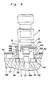
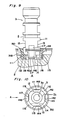
- the tensioning device essentially consists of three components, namely a chuck, generally designated 1, with a central draw bolt receptacle and reference elements on its underside, an overall designated 2 electrode holder with a flat surface and grooves on its top, and a draw bolt which can be anchored in the electrode holder 2 3rd
- the electrode holder 2 is square in plan view and has two pairs of parallel, opposite side surfaces 22, 24, 26, 28, of which the side surfaces 22, 24 of the first pair are exactly in the x direction and the side surfaces 26, 28 of the second pair are exactly extend in the y direction.
- the flat ground surface 30 is parallel to the xy plane and thus at right angles to the side surfaces 22, 24, 26, 28.
- two pairs of grooves 32, 34, 36, 38 are made of the same, each rectangular cross-section , of which each groove 32, 34 of the first pair is placed symmetrically to the central plane 4 of the electrode holder 2 containing the x-direction and is located between a central bore 40 of the electrode holder 2 and the side surface 26. 28 extends.
- Each groove 36, 38 of the second pair is symmetrical about the central plane 5 of the electrode holder 2 containing the y-direction and extends between the central bore 40 and the side surface 22.
- the groove 32 forms opposite edges 32a, 32b with respect to the central plane 4 and the groove 34 forms opposite edges 34a, 34b.
- the grooves 32, 34, 36, 38 divide the surface 30 into four surface sections 30a to 30d, of which the surface section 30a in that by the side surfaces 22 and 26, the surface section 30b in that by the side surfaces 26 and 24, the surface section 30c in that is arranged by the side surfaces 24 and 28 and the surface section 30d in the corner section of the electrode holder upper side each formed by the side surfaces 28, 22.
- each flank of each groove which starts from one of the mentioned edges, a slightly downward incision is cut into the material of the electrode holder 2, which has approximately a depth corresponding to the groove width, in about a third of the groove depth.
- Each incision has a length that is at least equal to the length of the associated edge.
- the two opposite cuts 31a and 31b start from the groove 32, the two opposite cuts 33a, 33b from the groove 34, the two opposite cuts 35a, 35b from the groove 36 and the two opposite cuts 37a, 37b from the groove 38 .
- the inner ends of the incisions are provided with the aforementioned reference numerals.
- the incisions enable the electrode holder material remaining between them and the adjacent surface section to take the form of a lip which is elastic in the z direction and which is provided with the respective edge.
- the opposite lips delimiting the groove 32 on both sides are denoted by 32c, 32d, the lips delimiting the groove 34 by 34c, 34d, the lips 36 delimiting the groove 36 by 36c, 36d and the lips 38 delimiting the groove 38 by 38c, 38d.
- an electrode 9 can be attached to the underside of the electrode holder 2.
- One fastening option consists in introducing a through hole for a screw bolt, for example the screw bolt 15, into each of the four surface sections 30a to 30d, with the aid of which the electrode 9 can be screwed onto the electrode holder 2.
- the exact location of each through hole 42, 44, 46, 48 is explained below.
- Each through hole 42, 44, 46, 48 is expanded at the top of the electrode holder 2 so that when the electrode 9 is screwed on, none of the bolts protrudes beyond the surface 30.
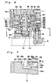
- the chuck 1 connected to the EDM machine has an underside, which is designed as follows according to Figures 1 and 3.
- the chuck 1 is at the bottom of a cylindrical outer contour.
- an annular surface 50 is ground precisely so that it lies exactly parallel to the xy plane and thus transversely to the center line 1 a of the chuck 1.
- the ring surface 50 encloses a circular surface 51, on the surface quality of which no special requirements have to be made. In the center of the circular surface 51, the draw bolt receptacle 10 opens.
- the square surface 30 of the electrode holder 2 is dimensioned in the x and y directions with respect to the outer diameter of the annular surface 50 and to the outer diameter of the circular surface 51 such that when the side surfaces are projected 22, 24, 26, 28 on the underside of the chuck, these lie entirely within the annular surface 50 and completely outside the circular surface 51, as indicated by dashed lines in FIG. 1.
- the respective side surfaces 22, 24, 26, 28 on the ring surface 50 and the periphery of the circular surface 51 lie in the four fields, which are defined by the central plane 6 containing the x-direction and the the center plane 7 of the ring surface 50 containing the y direction results in each case ring surface sections 50a, 50b, 50c, 50d.
- a post 52, 54, 56, 58 with a cylindrical cross section projects from each of the four ring surface sections.
- the posts can be in one piece with the chuck part 72 carrying the annular surface 50.
- the posts 52, 54, 56, 58 for receiving a machine screw 53, 55, 57, 59 are drilled in the center in such a way that the machine screws do not protrude from an end-side, annular reference surface 52a, 54a, 56a, 58a.
- the reference surfaces are kept very narrow by appropriate bevels to the through holes and to the outer periphery of the respective post.
- the reference surfaces 52a, 54a, 56a and 58a are ground flat, have the same distance from the ring surface 50 and are exactly parallel to the xy plane.
- each strip 62, 64, 66 and 68 of the same From the circular surface 51 protrude two pairs of strips 62, 64, 66 and 68 of the same, each essentially rectangular cross-section between the draw pin receptacle 10 and the periphery of the circular surface 51, each strip 62, 64 of the first pair symmetrical to the central plane 6 and each bar 66, 68 of the second pair is placed symmetrically to the central plane 7.
- the strips are worked out of the material of the chuck part 72.
- the outer contours of the strips are the same, so that only that of the strip 62 is described in more detail.
- the strip 62 has three pairs of flat side surfaces which extend transversely to the periphery of the circular surface and symmetrically to the central plane 6: the side surfaces 61a, 61b adjoining the circular surface 51 are essentially perpendicular to the circular surface 51. Those adjoining the side surfaces 61a, 61b Side surfaces 63a, 63b are only slightly inclined towards the center plane 6, while the side surfaces 65a, 65b extending between the end surface 62a of the strip 62 and the side surfaces 63a, 63b enclose a larger angle with the center plane 6, for example approximately 45 °.
- the side surfaces 63a, 63b serve as reference surfaces for the exact positioning of the electrode holder 2 in the x-y plane.
- the transition from the side surfaces 61a, 61b to the side surfaces 63a, 63b has a distance from the ring surface 50 that is smaller than the distance between the reference surfaces 52a, 54a, 56a, 58a and the ring surface 50.
- the distance of the transition is from the less inclined side surfaces 63a, 63b to the more inclined side surfaces 65a, 65b to the ring surface 50 is greater than the distance of each of the reference surfaces 52a, 54a, 56a, 58a to the ring surface 50.
- the end surface 62a lies at such a height above the ring surface 50 that when the electrode holder 2 is attached to the chuck 1, the bottom of the groove 32 is not touched by the bar 62.
- the reference surfaces 52a, 54a, 56a, 58a lie on ring-shaped support surfaces 42a, 44a, 46a, 48a of the surfaces cuts 30a, 30b, 30c, 30d so that the electrode holder 2 is clearly positioned in the z direction.
- the strips 62, 64, 66, 68 penetrate the grooves 32, 34, 36, 38 with the more inclined side surfaces 65a, 65b, while the less inclined reference surfaces 63a, 63b contact the edges 32a, 32b and in the course of the tensioning process bend the lips 32c, 32d axially inward until the aforementioned position of the electrode holder fixed in the z-direction is taken (FIG.
- edges 32a, 32b, 34a, 34b, 36a, 36b, 38a, 38b as well as the parts of the strips that have the reference surfaces and the posts with the reference surfaces can be particularly hardened;
- the strip 68 has an attachment 68a made of hard metal or tungsten carbide for this purpose, on which the reference surfaces 67a, 69b are formed.
- This type of position fixation of the electrode holder 2 has the advantage that the electrode holder 2 has a flat surface 30 which, like the planes and side edges 22, 24, 26, 28 aligned precisely in the x direction and the y direction, as reference surfaces can be used to measure the electrode 9 during its manufacture outside the die-sinking EDM machine.
- Each through hole 42, 44, 46, 48 is in an area of the associated surface section 30a, 30b, 30c, 30d arranged entirely within the support surfaces 42a, 44a, 46a, 48a.
- each of the grooves 32, 34, 36, 38 opens into the central bore 40 of the electrode holder 2.
- the wall sections 40a, 40b, 40c, 40d of the central bore 40 remaining between two adjacent grooves are along part of their axial thickness the center bore 40 in front (FIGS. 2 and 7) to form tongues 102, 104, 106, 108, which serve as locking elements for fastening the tension bolt 3 to the electrode holder 2.
- the chuck 1 has a cup-shaped chuck part 72, on the underside of which the annular surface 50 is formed.
- the chuck part 72 is fastened to a machine-side plate 74 by means of bolts.
- the plate 74 has a central blind hole 76 which is aligned with the draw bolt receptacle 10 and is surrounded by an annular wall 78. Between the wall 78 and the inside of the chuck part 72 there is an annular space in which a retaining ring 80 is axially displaceable.
- a spring 82 supported on the inner bottom of the chuck part 72 acts on the retaining ring 80 in an upper closed position, in which the retaining ring 80 is shown in FIG. 6.
- the retaining ring 80 is guided on the outer surface of the cheek 78 and an opposite inner surface of the chuck part 72 during its axial movement.
- a further guide of the retaining ring 80 is provided on the outer surface of a guide ring 84 which fixes the draw bolt receptacle 10 in the central bore of the chuck part 72 and extends in the direction of the wall 78.
- Between the wall 78 and the guide ring 84 are equally distributed balls 86, 88 held around the periphery of the draw bolt receptacle 10, which due to a with tapered recess in the retaining ring 80 can move radially outwards during its downward movement and then open the way for the head 90 of the draw bolt 3.
- the tension bolt 3 has a taper 92 into which the balls 86, 88 are pressed by the retaining ring 80 when the retaining ring 80 moves upward, and thus hold the tension bolt 3 axially.
- an annular compressed air chamber 94 is formed below the retaining ring 80, which can be connected to a compressed air source via a channel 96 which penetrates the jacket 97 of the chuck part 72. Furthermore, the compressed air chamber 94 is connected to 4 channels 98 which pass through the bottom of the chuck part 74 and which continue in compressed air channels 51a of the machine screws 53, 55, 57, 59. If the channel 96 is connected to a compressed air source, the retaining ring 80 is pressed in addition to the action of the spring 82 in the closed position, at the same time compressed air escaping through the air channels 51a and the support surfaces 42a, 44a, 46a, 48a possibly placed thereon when the electrode holder 2 is attached located particles cleans.
- the spring 82 no longer needs to be designed so that it alone has to apply the pressure required to press the electrode holder 2 with the electrode 9 against the reference surfaces. Rather, the spring 82 only needs to be designed according to safety aspects, which ensure that in the event of a failure of the compressed air source, the electrode holder 2 together with the tension bolt 3 does not accidentally fall out of the chuck 1.
- the upper side of the retaining ring 80 is passed to compressed air via channels 91, 93 Source connected, the pressure overcomes the force of the spring 82 (when the closing air pressure is removed) and the retaining ring 80 in its lower open position, the balls 86, 88 can escape into the depression of the retaining ring 80 and the way for release the head 90 of the draw bolt 3.
- the cylindrical lower section 11 has a flattening 12, 13 on each of two opposite circumferential sections, on which the tension bolt 3 can be gripped, for example, by the fork of a gripper and transported by the latter. Below the flats 12, 13, the tension bolt 3 has a length that is slightly greater than the depth of the central bore 40.
- lugs 112, 114, 116, 118 project equally radially outward and have a length in the circumferential direction that is not greater than the width of one of the grooves 32, 34, 36, 38. In the radial direction, the lugs 112, 114, 116, 118 do not project any further than the clear width of the central bore 40 in its lowermost section. Between two adjacent lugs 112, 114, 116, 118, 3 guide grooves 111, 113, 115, 117 are formed in the form of flattened portions of the cylindrical outer contour of section 11, starting from the lower end face 3b of the tension bolt.
- the two opposite guide grooves 111, 115 which respectively extend parallel to the flats 12 and 13, end in the axial direction at a distance from the associated flattening 12, 13, as can be seen from the example of the guide groove 111 FIG. 8.
- the two other, opposite guide grooves 113, 117 extend at the section 11 in the axial direction further away from the end face 3b and end at the level of the flats 12, 13, as can be seen in FIGS. 8 and 9 on the guide groove 117.
- the lower section 11 of the draw bolt 3 is of one with 150 designated slide includes, which in the illustrated embodiment has the shape of a finger-provided locking ring, for example made of plastic.
- the ring 150 is displaceable in the axial direction on the lower section 11 and has a circumferential, radially projecting grip strip 152 above the fingers.
- the fingers 142, 144, 146, 148 each have a width which practically completely fills the space between two adjacent lugs 112, 114, 116, 118.
- each finger 142, 144, 146, 148 has a thickening from its lower end, so that each of the thickenings can dip into one of the guide grooves 111, 113, 115, 117.
- the opposite fingers 142, 146 remain constantly in engagement with the associated guide grooves 113, 115 via their rear thickenings, while the opposite radially elastic fingers 144, 148 with their rear thickenings only in the locking position shown in FIG. 9 in the shorter guide grooves 111, 115 engage, but in the unlocked, raised position shown in FIG. 8, however, have slid out of the guide grooves 111, 113 upwards.
- each of the fingers 142, 144, 146, 148 is in any case smaller than the width of one of the grooves 32, 34, 36, 38. Due to the engagement of the rear thickenings of the fingers 142, 146 in the guide grooves 113, 117, the ring is 150 non-rotatably on the lower section 11 of the draw bolt 3, but held axially displaceable.
- the lower section 11 is inserted into the central bore 40 such that each of the lugs 112, 114, 116, 118 in the formed by the grooves 32, 34, 36, 38 Gap between the tongues 102, 104, 106, 108 can penetrate to the bottom of the central bore 40.
- the ring 150 if it is not in the raised position from the start, becomes by belching the lower side of the fingers 142, 144, 146, 148 on the tongues 102, 104, 106, 108 when the draw bolt 3 is pushed further into the central bore into the raised position shown in FIG. 3 axially displaced on the draw bolt 3.
- the draw bolt 3 is rotated in the central bore 40 by an angle of approximately 45 °, in any case to such an extent that the fingers 142, 144, 146, 148 can penetrate into the spaces between the tongues formed by the grooves 32, 34, 36.
- the ring 150 is then pushed by hand into the locking position shown in FIG. 9 on the lower section 11 so that the fingers are between the tongues and prevents the tension bolt 3 from rotating further.
- one of the strips 142, 144, 146, 148 underlies one of the tongues 102, 104, 106, 108.
- the draw bolt 3 is coupled in this way to the electrode holder 2 and can then be inserted into the chuck a die sinking EDM machine.
- the ring 150 is moved by hand on the handle bar 152, which is easily accessible above the grooves and the upper, radially expanded sections of the central bore, axially upwards on the lower section 11, the fingers 144, 148 due to their radial elasticity can easily come out of the guide grooves 111, 115.
- the draw bolt 3 can then be rotated so far that its lugs come out of engagement with the tongues, so that the draw bolt 3 can then be lifted up from the electrode holder 2 without hindrance.
- the above-described locking mechanism for coupling the pull bolt 3 to the electrode holder 2 is not limited to the special configuration of the ring 150. In its place, a simple slide that is axially displaceably fastened on the lower section 11 is also sufficient, which for locking purposes can engage either in one of the grooves or in a radial recess on one of the tongues in a circumferential direction.
Landscapes
- Engineering & Computer Science (AREA)
- Mechanical Engineering (AREA)
- Chemical & Material Sciences (AREA)
- Chemical Kinetics & Catalysis (AREA)
- Electrochemistry (AREA)
- Electrical Discharge Machining, Electrochemical Machining, And Combined Machining (AREA)
Abstract
Beschrieben wird eine Spannvorrichtung für ein Werkzeug (9) an einer Werkzeugmaschine, insbesondere einer Senkerodiermaschine, mit einem Spannfutter (1), welches zwei aus der Unterseite (51) des Spannfutters vorstehende Leisten (62, 64, 66, 68) aufweist, die mit Anlageflächen (63a, 63b, 67a) zur Ausrichtung des Werkzeugs in einer x-Richtung und einer y-Richtung, die quer zur Mittellinie (1a) des Spannfutters weisen, versehen sind. Um das Werkzeug beliebig oft wiederholbar und jeweils mit außerordentlich hoher Genauigkeit in einer vorgegebenen Lage am Spannfutter positionieren zu können, ist vorgesehen, daß von der Unterseite des Spannfutters mehrere Pfosten (52, 54, 56, 58) vorstehen, welche an ihren freien Stirnflächen in der x-y-Ebene sich erstreckende Referenzflächen (52a, 54a, 56a, 58a) aufweisen, wobei die Leisten exzentrisch und winkelmäßig zueinander versetzt ausgebildet sind, und daß ein Werkzeughalter (2) zur Anlage an die Pfosten eine plane Oberfläche (30) aufweist, in welche zwei Paare von auf die Leisten (62,64,66, 68) ausgerichteten Nuten (32, 34, 36, 38) mit zur Anlage an die Leisten vorgesehenen elastischen Lippen geschnitten sind, wobei der Werkzeughalter (2) eine Mittelbohrung (40) mit Arretierelementen zur arretierenden und lösbaren Aufnahme eines Zugbolzens (3) besitzt.The invention relates to a clamping device for a tool (9) on a machine tool, in particular a die sinking EDM machine, with a chuck (1) which has two strips (62, 64, 66, 68) protruding from the underside (51) of the chuck Contact surfaces (63a, 63b, 67a) for aligning the tool in an x-direction and a y-direction, which face transversely to the center line (1a) of the chuck, are provided. In order to be able to repeat the tool any number of times and in each case with extraordinarily high accuracy in a given position on the chuck, it is provided that several posts (52, 54, 56, 58) protrude from the underside of the chuck, which in their free end faces have reference surfaces (52a, 54a, 56a, 58a) extending in the xy plane, the strips being eccentrically and angularly offset from one another, and in that a tool holder (2) for contacting the posts has a flat surface (30), in which two pairs of grooves (32, 34, 66, 68) oriented on the strips (32, 34, 36, 38) are cut with elastic lips provided for contact with the strips, the tool holder (2) having a central bore (40) with locking elements for locking and releasable reception of a draw bolt (3).
Description
Die Erfindung betrifft eine Spannvorrichtung für ein Werkzeug an einer Werkzeugmaschine, insbesondere einer Senkerodiermaschine, mit einem Spannfutter, welches zwei aus der Unterseite des Spannfutters vorstehende Leisten aufweist, die mit Referenzflächen zur Ausrichtung des Werkzeugs in einer x-Richtung und einer y-Richtung, die quer zu der Mittellinie des Spannfutters weisen, versehen sind.The invention relates to a clamping device for a tool on a machine tool, in particular a die-sinking EDM machine, with a chuck which has two ledges protruding from the underside of the chuck, which with reference surfaces for aligning the tool in an x-direction and a y-direction point across the center line of the chuck, are provided.
Aus der europäischen Patentanmeldung mit der Veröffentlichungsnummer 111 092 ist eine Kupplungsvorrichtung bekannt, die auch bei einer Senkerodiermaschine eingesetzt werden kann. Dabei erfolgt die Bearbeitung eines Werkstückes funkenerosiv mittels einer Elektrode, welche bei der bekannten Kupplungsvorrichtung mit dem Spannfutter einer Pinole der Senkerodiermaschine verbunden werden muß. Bei einer Senkerodiermaschine ist ein bezüglich der Maschine festes Koordinatensystem vorgegeben, dessen x-y-Ebene quer zu der in z-Richtung ausgeführten Senkbewegung der Pinole liegt. Die Mittellinie des Spannfutters erstreckt sich dabei in z-Richtung. Zur Lagepositionierung der Elektrode in dem Koordinatensystem sieht die bekannte Kupplungsvorrichtung vor, daß auf das Werkzeug (Elektrode) mit Referenzflächen versehene Pfosten aufgesetzt werden, die beim Einspannen des Werkzeugs gegen eine am Spannfutter vorgesehene Fläche zur Fixierung in z-Richtung anliegen. Ferner weist die Unterseite des Spannfutters Prismenzapfen, die zur Fixierung der Elektrode in der x-y-Ebene in Öffnungen einer Mitnehmerscheibe eingreifen, welche auf der Elektrode befestigt ist. Dabei dringt ein zentraler Zapfen des Spannfutters in ein Mittelloch und ein exzentrischer Zapfen in einen Schlitz der Mitnehmerscheibe ein.From the European patent application with the
Demgegenüber liegt der Erfindung die Aufgabe zugrunde, die eingangs genannte Spannvorrichtung derart auszubilden, daß das Werkzeug ohne Zwischenschaltung einer Mitnehmerscheibe beliebig oft wiederholbar und jeweils mit außerordentlich hoher Genauigkeit in einer vorgegebenen Lage am Spannfutter positoniert werden kann. Insbesondere soll ein Referenzsystem geschaffen werden, das eine genaue Herstellung der Elektrode außerhalb der Maschine erlaubt, ohne daß die fertige Elektrode in der Maschine justiert werden muß.In contrast, the invention has for its object to design the clamping device mentioned in such a way that the tool can be repeated as often as required without the interposition of a drive plate and each position with extremely high accuracy in a predetermined position on the chuck. In particular, a reference system is to be created which allows the electrode to be manufactured precisely outside the machine without the finished electrode having to be adjusted in the machine.
Ferner soll mit der Erfindung die genannte Spannvorrichtung mit einer Kupplungsvorrichtung ausgerüstet werden, welche ein schnelles Kuppeln und Lösen des Werkzeugs mit bzw. von dem Spannfutter gestattet.Furthermore, with the invention, the mentioned clamping device is to be equipped with a coupling device which allows the tool to be quickly coupled and released with or from the chuck.
Dazu ist erfindungsgemäß vorgesehen, daß bei der eingangs genannten Spannvorrichtung von der Unterseite des Spannfutters mehrere Pfosten vorstehen, welche an ihren freien Stirnflächen in der x-y-Ebene sich erstreckende Referenzflächen aufweisen, wobei die Leisten exzentrisch und winkelmäßig zueinander versetzt ausgebildet sind, und daß ein Werkzeughalter zur Anlage an die Pfosten eine plane Oberfläche aufweist, in welche zwei Paare von auf die Leisten ausgerichteten Nuten mit zur Anlage an die Leisten vorgesehenen, elastischen Lippen geschnitten sind, wobei der Werkzeughalter eine Mittelbohrung mit Arretierelementen zur arretierenden und lösbaren Aufnahme eines Zugbolzens besitzt. Damit liegen die Gegenreferenzen für die x-, y- und z-Richtung auf dem Werkzeughalter in einer gemeinsamen Ebene, nämlich in seiner Oberfläche, was eine einfache und zugleich äußerst exakte Herstellung erlaubt.For this purpose, it is provided according to the invention that in the clamping device mentioned at the outset a plurality of posts protrude from the underside of the chuck, which have reference surfaces extending on their free end faces in the xy plane, the strips being eccentrically and angularly offset from one another, and that a tool holder has a flat surface for abutment against the posts, into which two pairs of grooves aligned with the strips are cut with elastic lips provided for abutment against the strips, the tool holder having a central bore with locking elements for arresting and releasably receiving a draw bolt. The counter-references for the x, y and z directions are thus on the tool holder in a common plane, namely in its surface, which allows simple and at the same time extremely precise manufacture.
Das Werkzeug kann auf der der Oberfläche gegenüberliegenden Seite am Werkzeughalter befestigt und außerhalb der Werkzeugmaschine exakt auf seine vorgesehene Form bearbeitet werden. Dazu empfiehlt es sich in Weiterbildung der Erfindung, wenn Seitenflächen- oder kanten des Werkzeughalters exakt auf die x- bezw. y-Richtung ausgerichtet sind.The tool can be attached to the tool holder on the side opposite the surface and can be machined exactly to its intended shape outside the machine tool. To this end, it is recommended in a further development of the invention if the side surfaces or edges of the tool holder exactly match the x or. y direction are aligned.
Das fertige Werkzeug mit Werkzeughalter wird sodann mit Hilfe des in das Spannfutter eindringenden Zugbolzens am Spannfutter eingespannt, wobei die Oberfläche des Werkzeughalters als Gegenreferenz für die Pfosten und die Nuten als Gegenreferenz für die Leisten dienen.The finished tool with tool holder is then clamped on the chuck with the aid of the pull bolt penetrating into the chuck, the surface of the tool holder serving as a counter-reference for the posts and the grooves as a counter-reference for the strips.
Zweckmäßig sind am Spannfutter zwei Paare von Leisten derart vorgesehen, daß die Verbindungslinie eines Leistenpaares die Verbindungslinie des anderen Leistenpaares recktwinklig kreuzt und die Leisten eines Paares bezüglich der Mitte der Oberfläche einander gegenüberliegen.Two pairs of strips are expediently provided on the chuck in such a way that the connecting line of one pair of strips crosses the connecting line of the other pair of strips at a right angle and the strips of a pair lie opposite one another with respect to the center of the surface.
Mit besonderem Vorteil besitzt der Werkzeughalter wenigstens zwei Seitenflächen, von denen eine zu einem ersten Paar der Nuten und die andere zu dem zweiten Paar der Nuten exakt parallel verläuft. Dies erleichtert die Verwendung des Werkzeughalters zur Vermessung des Werkzeugs innerhalb des maschineneigenen Koordinatensystems außerhalb der Maschine.It is particularly advantageous for the tool holder to have at least two side surfaces, one of which runs exactly parallel to a first pair of grooves and the other to the second pair of grooves. This facilitates the use of the tool holder for measuring the tool within the machine's own coordinate system outside the machine.
In bevorzugter Ausführungsform der Erfindung ist vorgesehen, daß die Arretierelemente wenigstens einen in die Mittelbohrung vorstehenden Steg aufweisen und daß am unteren Ende des Zugbolzens wenigstens eine radial vorstehende Nase zum Untergreifen des Stegs ausgebildet ist. Ferner kann am Zugbolzen ein axial verschiebbarer Schieber in der Nähe seines unteren Endes gehalten sein. Durch einfaches Einsetzen des unteren Endes des Zugbolzens in die Mittelbohrung und Verdrehen des Zugbolzens bis zum Untergreifen seiner Nase unter den Steg läßt sich der Zugbolzen schnell und sicher mit dem Werkzeughalter koppeln und durch den beispielsweise in eine Vertiefung des Werkstückhalters eingreifenden Schieber arretieren.In a preferred embodiment of the invention it is provided that the locking elements have at least one web projecting into the central bore and that at least one radially projecting nose is formed at the lower end of the draw bolt for engaging under the web. Furthermore, an axially displaceable slide can be held near its lower end on the draw bolt. By simply inserting the lower end of the draw bolt into the center hole and twisting the draw bolt until it grips under the nose under the web, the draw bolt can be quickly and safely coupled to the tool holder and locked by the slider, which engages, for example, in a recess in the workpiece holder.
In bevorzugter Ausgestaltung der Erfindung braucht der Zugbolzen nur um etwa 45° gedreht zu werden, wenn zwischen je zwei in Umfangsrichtung der Mittelbohrung benachbarten Nuten je ein Steg ausgebildet ist. Um eine Beeinflussung der am Werkzeughalter ausgebildeten Referenzmittel durch die Arretierung des Zugbolzens auszuschließen, erweist es sich als zweckmäßig, den Boden der Mittelbohrung wenigstens um die Stärke der Nasen tiefer zu legen als Basis der Nuten. Ferner erweist es sich als zweckmäßig, am unteren Ende des Zugbolzens vier umfangmäßig gleich beabstandete Nasen vorzusehen, wobei die umfangmäßige Breite jeder Nase nicht größer ist als der umfangmäßige Zwischenraum zwischen zwei benachbarten Stegen, insbesondere als die lichte Weite der Nuten.In a preferred embodiment of the invention, the draw bolt only needs to be turned by approximately 45 ° if a web is formed between two grooves adjacent in the circumferential direction of the central bore. In order to prevent the reference means formed on the tool holder from being influenced by the locking of the draw bolt, it proves to be expedient to lower the bottom of the central bore by at least the thickness of the lugs as the base of the grooves. Furthermore, it proves to be expedient to provide four lugs of equal circumferential spacing at the lower end of the draw bolt, the widened width of each lug being no greater than the circumferential gap between two adjacent webs, in particular the inside width of the grooves.
Besonders vorteilhaft ist die Ausbildung des Schiebers als ein den Zugbolzen umfassender Ring, von welchem sich wenigstens ein, bevorzugt vier umfangmäßig gleich beabstandete Finger axial in Richtung auf das untere Ende des Zugbolzens erstrecken, deren jeweilige umfangmäßige Breite dem Abstand zwischen benachbarten Nasen entspricht.It is particularly advantageous to design the slide as a ring comprising the draw bolt, from which at least one, preferably four, equally spaced fingers extend axially in the direction of the lower end of the draw bolt, the circumferential width of which corresponds to the distance between adjacent lugs.
Die Handhabung des Schiebers bzw. des Rings wird vereinfacht, wenn der Schieber bzw. der Ring auf dem Zugbolzen unverdrehbar gehalten ist. Dazu empfiehlt es sich, am Umfang des Zugbolzens von seinem unteren Ende ausgehend vier gleich beabstandete Führungsnuten auszubilden, wobei je einer der Finger mit einer radialen Verdickung in je eine der Führungsnuten eintaucht. Zum Einrasten des Rings zur Arretierung der Kupplung zwischen Zugbolzen und Werkzeughalter ist wenigstens eine der Führungsnuten in axialer Richtung zweckmäßig kürzer ist als die anderen Führungsnuten, wobei dann wenigstens der in die kürzere Führungsnut eintauchende Finger radial elastisch ist.The handling of the slide or the ring is simplified if the slide or the ring is held non-rotatably on the draw bolt. For this purpose, it is advisable to form four equally spaced guide grooves on the circumference of the draw bolt, starting from its lower end, one of the fingers immersing in one of the guide grooves with a radial thickening. To lock the ring for locking the coupling between the draw bolt and tool holder, at least one of the guide grooves is expediently shorter in the axial direction than the other guide grooves, in which case at least the finger immersed in the shorter guide groove is radially elastic.
Weitere bevorzugte Ausgestaltungen der Erfindung sind in den Unteransprüchen angegeben.Further preferred embodiments of the invention are specified in the subclaims.
Die Erfindung hat besondere Bedeutung für die Herstellung einer Elektrode für die funkenerosive Bearbeitung eines Werkstückes mittels einer Senkerodiermaschine. Die Erfindung wird daher für diese Anwendung nachstehend anhand des in der beigefügten Zeichnung dargestellten Ausführungsbeispiels im einzelnen beschrieben. Es zeigen:
- Fig. 1 eine Draufsicht auf die Unterseite eines maschinenseitigen Spannfutters;
- Fig. 2 eine Draufsicht auf die Oberseite eines Elektrodenhalters ohne Zugbolzen;
- Fig. 3 eine Ansicht des an das Spannfutter mittels eines Zugbolzens angesetzten Elektrodenhalters, teilsweise im Schnitt;
- Fig. 4 eine Einzelheit aus
Figur 3 in vergrößertem Maßstab; - Fig. 5 eine Ansicht des Elektrodenhalters mit eingesetztem Zugbolzen;
- Fig. 6 eine Schnittansicht des Spannfutters mit angesetztem Elektrodenhalter;
- Fig. 7: einen Schnitt durch den Elektrodenhalter längs der Linie II-II aus Fig. 2;
- Fig. 8: die Ansicht eines Zugbolzens mit Arretierring, teilweise im Schnitt, sowie des in x-Richtung geschnittenen Elektrodenhalters;
- Fig. 9: eine Ansicht des um 90° gedrehten Zugbolzens aus Fig. 8 mit eingerastetem Arretierring und des in y-Richtung geschnittenen Elektrodenhalters; und
- Fig. 10: eine Ansicht des Zugbolzens mit Arretierring von unten.
- Figure 1 is a plan view of the underside of a machine chuck.
- Figure 2 is a plan view of the top of an electrode holder without tie bolts.
- 3 shows a view of the electrode holder attached to the chuck by means of a pull bolt, partly in section;
- 4 shows a detail from FIG. 3 on an enlarged scale;
- Fig. 5 is a view of the electrode holder with the tie bolt inserted;
- 6 shows a sectional view of the chuck with the electrode holder attached;
- 7: a section through the electrode holder along the line II-II from FIG. 2;
- 8: the view of a draw bolt with locking ring, partly in section, and of the electrode holder cut in the x direction;
- FIG. 9: a view of the pull bolt from FIG. 8 rotated by 90 ° with the locking ring engaged and the electrode holder cut in the y direction; and
- Fig. 10: a view of the draw bolt with locking ring from below.
Die Spannvorrichtung besteht im wesentlichen aus drei Bauteilen, nämlich einem im ganzen mit 1 bezeichneten Spannfutter mit einer zentrischen Zugbolzenaufnahme und Referenzelementen an seiner Unterseite, einem im ganzen mit 2 bezeichneten Ekektrodenhalter mit planer Oberfläche und Nuten an seiner Oberseite, sowie einem im Elektrodenhalter 2 verankerbaren Zugbolzen 3.The tensioning device essentially consists of three components, namely a chuck, generally designated 1, with a central draw bolt receptacle and reference elements on its underside, an overall designated 2 electrode holder with a flat surface and grooves on its top, and a draw bolt which can be anchored in the
Der Elektrodenhalter 2 ist in Draufsicht quadratisch und besitzt zwei Paare paralleler, gegenüberliegender Seitenflächen 22, 24, 26, 28, von denen die Seitenflächen 22, 24 des ersten Paares sich genau in x-Richtung und die Seitenflächen 26, 28 des zweiten Paares sich genau in y-Richtung erstrecken. Die plan geschliffene Oberfläche 30 liegt parallel zur x-y-Ebene und damit rechtwinkelig zu den Seitenflächen 22, 24, 26, 28. In die Oberseite des Elektrodenhalters 2 sind zwei Paare von Nuten 32, 34, 36, 38 von gleichem, jeweils rechtwinkeligem Querschnitt eingebracht, von denen jede Nut 32, 34 des ersten Paares symmetrisch zu der die x-Richtung enthaltenden Mittelebene 4 des Elektrodenhalters 2 gelegt ist und sich zwischen einer Mittelbohrung 40 des Elektrodenhalters 2 und der Seitenfläche 26 bezw. 28 erstreckt. Jede Nut 36, 38 des zweiten Paares ist symmetrisch zu der die y-Richtung enthaltenden Mittelebene 5 des Elektrodenhalters 2 gelegt und erstreckt sich zwischen der Mittelbohrung 40 und der Seitenfläche 22 bezw. Am Übergang zu der Oberfläche 30 bilden die Nut 32 bezüglich der Mittelebene 4 gegenüberliegende Kanten 32a, 32b und die Nut 34 gegenüberliegende Kanten 34a, 34b. Entsprechend finden sich am Übergang zur Oberfläche 30 an der Nut 36 bezüglich der Mittelebene 5 gegenüberliegende Kanten 36a, 36b und an der Nut 38 gegenüberliegende Kanten 38a, 38b. Die Nuten 32, 34, 36, 38 unterteilen die Oberfläche 30 in vier Oberflächenabschnitte 30a bis 30d, von denen der Oberflächenabschnitt 30a in dem durch die Seitenflächen 22 und 26, der Oberflächenabschnitt 30b in dem durch die Seitenflächen 26 und 24, der Oberflächenabschnitt 30c in dem durch die Seitenflächen 24 und 28 und der Oberflächenabschnitt 30d in dem durch die Seitenflächen 28, 22 jeweils gebildeten Eckenabschnitt der Elektrodenhalter-Oberseite angeordnet ist.The
In jede Flanke jeder Nut, die von einer der genannten Kanten ausgeht, ist in etwa einem Drittel der Nuttiefe ein leicht nach unten gebogener Einschnitt in das Material des Elektrodenhalters 2 eingeschnitten, der etwa eine der Nutbreite entsprechende Tiefe hat. Jeder Einschnitt hat eine Länge, die wenigstens gleich der Länge der zugehörigen Kante ist. So gehen von der Nut 32 die beiden gegenüberliegenden Einschnitte 31a und 31b, von der Nut 34 die beiden gegenüberliegenden Einschnitte 33a, 33b, von der Nut 36 die beiden gegenüberliegenden Einschnitte 35a, 35b und von der Nut 38 die beiden gegenüberliegenden Einschnitte 37a, 37b aus. In Figur 2 sind die inneren Enden der Einschnitte mit den vorstehend genannten Bezugszeichen versehen.In each flank of each groove, which starts from one of the mentioned edges, a slightly downward incision is cut into the material of the
Die Einschnitte ermöglichen, daß das zwischen ihnen und dem benachbarten Oberflächenabschnitt verbleibende Elektrodenhaltermaterial die Form einer in z-Richtung elastischen Lippe annimmt, welche mit der jeweiligen Kante versehen ist. Die die Nut 32 beiderseits begrenzenden, gegenüberliegenden Lippen sind mit 32c, 32d, die die Nut 34 begrenzenden Lippen mit 34c, 34d, die die Nut 36 begrenzenden Lippen mit 36c, 36d und die die Nut 38 begrenzenden Lippen mit 38c, 38d bezeichnet.The incisions enable the electrode holder material remaining between them and the adjacent surface section to take the form of a lip which is elastic in the z direction and which is provided with the respective edge. The opposite lips delimiting the
Wie Figur 6 zeigt, kann an der Unterseite des Elektrodenhalters 2 eine Elektrode 9 befestigt werden. Eine Befestigungsmöglichkeit besteht darin, in jeden der vier Oberflächenabschnitte 30a bis 30d je eine Durchgangsbohrung für einen Schraubbolzen, beispielsweise den Schraubbolzen 15, einzubringen, mit dessen Hilfe die Elektrode 9 an den Elektrodenhalter 2 angeschraubt werden kann. Die genaue Lage jeder Durchgangsbohrung 42, 44, 46, 48 wird weiter unten erläutert. Jede Durchgangsbohrung 42, 44, 46, 48 ist an der Oberseite des Elektrodenhalters 2 so erweitert, daß bei angeschraubter Elektrode 9 keiner der Schraubbolzen über die Oberfläche 30 vorsteht.As FIG. 6 shows, an electrode 9 can be attached to the underside of the
Das mit der Senkerodiermaschine verbundene Spannfutter 1 besitzt eine Unterseite, die gemäß Figuren 1 und 3 wie folgt gestaltet ist. Das Spannfutter 1 ist an der Unterseite von zylindrischer Außenkontur. An der Unterseite ist eine Ringfläche 50 exakt so plan geschliffen, daß sie genau parallel zur x-y-Ebene und damit quer zur Mittellinie 1a des Spannfutters 1 liegt. Die Ringfläche 50 umschließt eine Kreisfläche 51, an deren Oberflächengüte keine besonderen Anforderungen gestellt werden müssen. In der Mitte der Kreisfläche 51 mündet die Zugbolzenaufnahme 10. Die quadratische Oberfläche 30 des Elektrodenhalters 2 ist in Bezug auf den Außendurchmesser der Ringfläche 50 sowie auf den Außendurchmesser der Kreisfläche 51 so in x- und y-Richtung bemessen, daß bei einer Projektion der Seitenflächen 22, 24, 26, 28 auf die Unterseite des Spannfutters diese ganz innerhalb der Ringfläche 50 und ganz außerhalb der Kreisfläche 51 liegen, wie in Figur 1 gestrichelt angedeutet ist.The
Zwischen den Projektionen 22a, 24a, 26a, 28a, der jeweiligen Seitenflächen 22, 24, 26, 28 auf die Ringfläche 50 und der Peripherie der Kreisfläche 51 liegen in den vier Feldern, die sich durch die die x-Richtung enthaltende Mittelebene 6 und die die y-Richtung enthaltende Mittelebene 7 der Ringfläche 50 ergeben, jeweils Ringflächenabschnitte 50a, 50b, 50c, 50d. Aus jedem der vier Ringflächenabschnitte steht je ein im Querschnitt zylindrischer Pfosten 52, 54, 56, 58 vor. Die Pfosten können mit dem die Ringfläche 50 tragenden Spannfutterteil 72 einteilig sein. Alternativ sind die Pfosten 52, 54, 56, 58 zur Aufnahme je einer Maschinenschraube 53, 55, 57, 59 mittig so durchbohrt, daß die Maschinenschrauben über eine stirnseitige, ringförmige Referenzfläche 52a, 54a, 56a, 58a nicht vorstehen. Die Referenzflächen sind durch entsprechende Abschrägungen zu den Durchbohrungen und zu der Außenperipherie des jeweiligen Pfostens sehr schmal gehalten. Ferner sind die Referenzflächen 52a, 54a, 56a und 58a plan geschliffen, haben gleichen Abstand zur Ringfläche 50 und liegen genau parallel zur x-y-Ebene. Jede einzelne der Referenzflächen 52a, 54a, 56a und 58a wie auch ihre Gesamtheit bilden daher eine Referenz in z-Richtung für die genaue Positionierung der Elektrode 9 über den Elektrodenhalter 2, wenn letzterer mit der Oberfläche 30 gegen die Referenzflächen angezogen ist.Between the projections 22a, 24a, 26a, 28a, the respective side surfaces 22, 24, 26, 28 on the
Aus der Kreisfläche 51 stehen zwei Paare von Leisten 62, 64, 66 und 68 von gleichem, jeweils im wesentlichen rechtwinkeligem Querschnitt zwischen der Zugbolzenaufnahme 10 und der Peripherie der Kreisfläche 51 vor, von denen jede Leiste 62, 64 des ersten Paares symmetrisch zu der Mittelebene 6 und jede Leiste 66, 68 des zweiten Paares symmetrisch zur Mittelebene 7 gelegt ist. Die Leisten sind aus dem Material des Spannfutterteiles 72 herausgearbeitet. Die Außenkonturen der Leisten sind gleich, sodaß nur diejenige der Leiste 62 genauer beschrieben wird.From the
Die Leiste 62 hat drei Paare von ebenen Seitenflächen, die sich quer zur Peripherie der Kreisfläche und symmetrisch zur Mittelebene 6 erstrecken: Die an die Kreisfläche 51 angrenzenden Seitenflächen 61a, 61b verlaufen im wesentlichen senkrecht zur Kreisfläche 51. Die an die Seitenflächen 61a, 61b angrenzenden Seitenflächen 63a, 63b sind nur wenig zur Mittelebene 6 hin geneigt, während die sich zwischen der Stirnfläche 62a der Leiste 62 und den Seitenflächen 63a, 63b erstreckenden Seitenflächen 65a, 65b einen größeren Winkel mit der Mittelebene 6, beispielsweise ungefähr 45°, einschließen. Die Seitenflächen 63a, 63b dienen als Referenzflächen für die genaue Lagepositionierung des Elektrodenhalters 2 in der x-y-Ebene. Dazu hat der Übergang von den Seitenflächen 61a, 61b zu den Seitenflächen 63a, 63b von der Ringfläche 50 einen Abstand, der kleiner ist als der Abstand der Referenzflächen 52a, 54a, 56a, 58a zu der Ringfläche 50. Andererseits ist der Abstand des Übergangs von den wenig geneigten Seitenflächen 63a, 63b zu den stärker geneigten Seitenflächen 65a, 65b zu der Ringfläche 50 größer als der Abstand jeder der Referenzflächen 52a, 54a, 56a, 58a zu der Ringfläche 50. Selbstverständlich liegt die Stirnfläche 62a in solcher Höhe über der Ringfläche 50, daß bei an das Spannfutter 1 angesetztem Elektrodenhalter 2 der Boden der Nut 32 von der Leiste 62 nicht berührt wird.The
Wenn der Elektrodenhalter 2 an das Spannfutter 1 durch den Zugbolzen 3 herangezogen wird, liegen die Referenzflächen 52a, 54a, 56a, 58a auf ringförmigen Stützflächen 42a, 44a, 46a, 48a der Oberflächenab schnitte 30a, 30b, 30c, 30d auf, so daß der Elektrodenhalter 2 in z-Richtung eindeutig positioniert ist. Gleichzeitig dringen die Leisten 62, 64, 66, 68 in die Nuten 32, 34, 36, 38 mit den stärker geneigten Seitenflächen 65a, 65b ein, während die wenig geneigten Referenzflächen 63a, 63b die Kanten 32a, 32b kontaktieren und im Zuge des Spannvorgangs die Lippen 32c, 32d axial einwärts bis zur Einnahme der erwähnten, in z-Richtung fixierten Lage des Elektrodenhalters biegen (Fig. 4). Durch diese Art Eingriff der Leisten in die Nuten ergibt sich bei der genauen Positionierung des Elektrodenhalters 2 in z-Richtung gleichzeitig dessen genaue Positionierung in x-Richtung und in y-Richtung. Dabei schließt die dynamische Fixierung des Elektrodenhalters 2 in x- und y-Richtung (aufgrund der Elastizität der Lippen 32c, 32d; 34c, 34d; 36c, 36d; 38c, 38d) jegliches Spiel aus. Für die Herstellung der Referenzen am Elektrodenhalter 2 ist vorteilhaft, daß diese sämtlich in einer gemeinsamen Ebene liegen, so daß die Kanten 32a, 32b; 34a, 34b; 36a, 36b; 38a, 38b gleichzeitig mit der Bildung der Oberfläche 30 sich ergeben, ohne daß die Einstellung der den Elektrodenhalter herstellenden Maschine geändert werden muß.When the
Die Kanten 32a, 32b, 34a, 34b, 36a, 36b, 38a, 38b wie auch die die Referenzflächen aufweisenden Teile der Leisten und die Pfosten mit den Referenzflächen können besonders gehärtet sein; in Figur 3 ist zu erkennen, daß die Leiste 68 zu diesem Zweck einen Aufsatz 68a aus Hartmetall order Wolframkarbid besitzt, an welchem die Referenzflächen 67a, 69b ausgebildet sind.The
Diese Art der Lagefixierung des Elektrodenhalters 2 hat den Vorteil, daß der Elektrodenhalter 2 eine ebene Oberfläche 30 besitzt, die ebenso wie die Ebenen und genau auf der x-Richtung bzw. der y-Richtung ausgerichteten Seitenkanten 22, 24, 26, 28 als Bezugsflächen zur Vermessung der Elektrode 9 bei deren Herstellung außerhalb der Senkerodiermaschine herangezogen werden können.This type of position fixation of the
Jede Durchgangsbohrung 42, 44, 46, 48 ist in einem Bereich des zugehörigen Oberflächenabschnittes 30a, 30b, 30c, 30d angeordnet, der ganz innerhalb der Stützflächen 42a, 44a, 46a, 48a liegt. Dadurch wird die genaue Fixierung des Elektrodenhalters 2 in z-Richtung unmittelbar auf eine entsprechende Positionierung der Elektrode 9 übertragen.Each through
Im dargestellten Ausführungsbeispiel der Erfindung mündet jede der Nuten 32, 34, 36, 38 in die Mittelbohrung 40 des Elektrodenhalters 2. Die zwischen je zwei benachbarten Nuten verbleibenden Wandabschnitte 40a, 40b, 40c, 40d der Mittelbohrung 40 stehen längs eines Teiles ihrer axialen Stärke in die Mittelbohrung 40 vor (Figur 2 und 7) zur Bildung von Zungen 102, 104, 106, 108, die als Arretierelemente zum Befestigen des Zugbolzens 3 an dem Elektrodenhalter 2 dienen.In the illustrated embodiment of the invention, each of the
Gemäß Fig. 6 weist das Spannfutter 1 ein becherförmiges Spannfutterteil 72 auf, an dessen Unterseite die Ringfläche 50 ausgebildet ist. Das Spannfutterteil 72 ist mittels Bolzen an einer maschinenseitigen Platte 74 befestigt. Die Platte 74 besitzt ein zentrales Sackloch 76, das auf die Zugbolzenaufnahme 10 ausgerichtet ist und von einer ringförmigen Wand 78 umgeben ist. Zwischen der Wand 78 und der Innenseite des Spannfutterteils 72 ist ein Ringraum vorhanden, in welchem ein Haltering 80 axial verschiebbar ist. Eine sich am inneren Boden des Spannfutterteils 72 abstützende Feder 82 beaufschlagt den Haltering 80 in eine obere Verschlußstellung, in welcher der Haltering 80 in Figur 6 eingezeichnet ist. Der Haltering 80 ist an der Außenfläche der Wange 78 und einer gegenüberliegenden Innenfläche des Spannfutterteils 72 bei seiner axialen Bewegung geführt. Eine weitere Führung des Halteringes 80 ist an der Außenfläche eines Führungsringes 84 gegeben, welcher in der Mittelbohrung des Spannfutterteils 72 die Zugbolzenaufnahme 10 definierend befestigt und sich in Richtung auf die Wand 78 erstreckt. Zwischen der Wand 78 und dem Führungsring 84 sind um die Peripherie der Zugbolzenaufnahme 10 gleich verteilte Kugeln 86, 88 gehalten, welche aufgrund einer mit konischen Flächen versehenen Einsenkung im Haltering 80 bei dessen Abwärtsbewegung radial nach außen ausweichen können und dann den Weg für den Kopf 90 des Zugbolzens 3 freigeben. Unterhalb des Kopfes 90 weist der Zugbolzen 3 eine Verjüngung 92 auf, in welche die Kugeln 86, 88 bei Aufwärtsbewegung des Halterings 80 von diesem hineingedrückt werden und damit den Zugbolzen 3 axial halten.6, the
Erfindungsgemäß ist unterhalb des Halterings 80 eine ringförmige Druckluftkammer 94 gebildet, welche über einen Kanal 96, der den Mantel 97 des Spannfutterteils 72 durchdringt, an eine Druckluftquelle angeschlossen werden kann. Ferner ist die Druckluftkammer 94 mit 4 den Boden des Spannfutterteils 74 durchsetzenden Kanälen 98 verbunden, welche sich in Druckluftkanäle 51a der Maschinenschrauben 53, 55, 57, 59 fortsetzen. Wird der Kanal 96 an eine Druckluftquelle angeschlossen, wird der Haltering 80 zusätzlich zu der Wirkung der Feder 82 in Schließstellung gedrückt, wobei gleichzeitig durch die Luftkanäle 51a Druckluft entweicht und beim Ansetzen des Elektrodenhalters 2 die Stützflächen 42a, 44a, 46a, 48a von eventuell darauf befindlichen Teilchen reinigt. Wenn der Elektrodenhalter 2 an das Spannfutter 1 fest angesetzt wird, kann durch die Druckluftkanäle 51a keine Druckluft mehr entweichen, so daß sich der Schließdruck für den Haltering 80 erhöht. Dadurch steigt die Haltekraft des Futters für Elektrodenhalter mit Elektrode und Zugbolzen auf etwa das Dreifache.According to the invention, an annular
Mit dieser Einrichtung wird erreicht, daß die Feder 82 nicht mehr daraufhin ausgelegt zu werden braucht, daß sie alleine den zum Andrücken des Elektrodenhalters 2 mit Elektrode 9 gegen die Referenzflächen erforderlichen Anpressdruck aufbringen muß. Vielmehr braucht die Feder 82 nur nach Sicherheitsgesichtspunkten ausgelegt zu werden, die sicherstellen, daß bei Ausfall der Druckluftquelle der Elektrodenhalter 2 samt Zugbolzen 3 nicht aus dem Spannfutter 1 unbeabsichtigt herausfällt.With this device it is achieved that the
Zur Entnahme des Elektrodenhalters 2 mit Zugbolzen 3 wird die Oberseite des Halterings 80 über Kanäle 91, 93 an eine Druckluft quelle angeschlossen, deren Druck die Kraft der Feder 82 überwindet (wenn der Schließ-Luftdruck weggenommen ist) und den Haltering 80 in seine untere Offenstellung überführt, wobei die Kugeln 86, 88 in die Einsenkung des Halterings 80 nach außen entweichen können und den Weg für den Kopf 90 des Zugbolzens 3 freigeben.To remove the
Von dem Zugbolzen 3, der bis auf einige radiale Einschnitte im wesentlichen zylindrische Gestalt hat, wird hier nur sein unterer Abschnitt unterhalb einer Ringnut 8 für einen nicht dargestellten Dichtring beschrieben (Fig. 8 - 10). Der zylindrische untere Abschnitt 11 besitzt an zwei gegenüberliegenden Umfangsabschnitten je eine Abflachung 12, 13, an denen der Zugbolzen 3 beispielsweise von der Gabel eines Greifers erfaßt und von dieser transportiert werden kann. Unterhalb der Abflachungen 12, 13 hat der Zugbolzen 3 eine Länge, die etwas größer als die Tiefe der Mittelbohrung 40 ist. Am unteren Ende 14 des Zugbolzens 3 stehen radial nach außen vier umfangmäßig gleich beabstandete Nasen 112, 114, 116, 118 vor, die in Umfangsrichtung eine Länge haben, die nicht größer ist als die Breite einer der Nuten 32, 34, 36, 38. In radialer Richtung stehen die Nasen 112, 114, 116, 118 nicht weiter vor als die lichte Weite der Mittelbohrung 40 in ihrem untersten Abschnitt beträgt. Zwischen je zwei benachbarten Nasen 112, 114, 116, 118 sind ausgehend von der unteren Stirnfläche 3b des Zugbolzens 3 Führungsnuten 111, 113, 115, 117 in Form von Abflachungen der zylindrischen Außenkontur des Abschnittes 11 ausgebildet. Die beiden gegenüberliegenden Führungsnuten 111, 115, welche beziehentlich sich parallel zu den Abflachungen 12 und 13 erstrecken, enden in axialer Richtung mit Abstand vor der zugehörigen Abflachung 12, 13, wie am Beispiel der Führungsnut 111 Fig. 8 erkennen läßt. Die beiden anderen, gegenüberliegenden Führungsnuten 113, 117 reichen am Abschnitt 11 in axialer Richtung weiter von der Stirnfläche 3b weg und enden in der Höhe der Abflachungen 12, 13, wie Figuren 8 und 9 an der Führungsnut 117 erkennen lassen.Of the
Der untere Abschnitt 11 des Zugbolzens 3 ist von einem im ganzen mit 150 bezeichneten Schieber umfaßt, der im dargestellten Ausführungsbeispiel die Form eines mit Fingern versehenen Arretierrings beispielsweise aus Kunststoff besitzt. Der Ring 150 ist auf dem unteren Abschnitt 11 in axialer Richtung verschiebbar und und weist oberhalb der Finger eine umlaufende, radial vorstehende Griffleiste 152 auf. Von der Griffleiste 152 erstrecken sich abwärts vier in Umfangsrichtung gleich beabstandete Finger 142, 144, 146, 148, die mit ihren Innenflächen am Mantel des Abschnittes 11 anliegen. In Umfangsrichtung besitzen die Finger 142, 144, 146, 148 jeweils eine Breite, die den Zwischenraum zwischen je zwei benachbarten Nasen 112, 114, 116, 118 praktisch vollständig ausfüllt. An der Rückseite weist jeder Finger 142, 144, 146, 148 von seinem unteren Ende her eine Verdickung auf, so daß jede der Verdickungen in je eine der Führungsnuten 111, 113, 115, 117 eintauchen kann. Dabei bleiben die gegenüberliegenden Finger 142, 146 über ihre rückseitigen Verdickungen mit den zugehörigen Führungsnuten 113, 115 ständig im Eingriff, während die gegenüberliegenden radial elastischen Finger 144, 148 mit ihren rückseitigen Verdickungen nur in der in Fig. 9 dargestellten arretierenden Stellung in die kürzeren Führungsnuten 111, 115 eingreifen, in der in Fig. 8 dargestellten entarretierten, angehobenen Stellung jedoch nach oben aus den Führungsnuten 111, 113 herausgeglitten sind. Die größte Breite jedes der Finger 142, 144, 146, 148 ist jedenfalls kleiner als die Breite einer der Nuten 32, 34, 36, 38. Aufgrund des Eingriffs der rückseitigen Verdickungen der Finger 142, 146 in den Führungsnuten 113, 117 ist der Ring 150 auf dem unteren Abschnitt 11 des Zugbolzens 3 unverdrehbar, jedoch axial verschieblich gehalten.The
Zum Kuppeln des mit dem Ring 150 versehenen Zugbolzens 3 mit dem Elektrodenhalter 2 wird der untere Abschnitt 11 so in die Mittelbohrung 40 eingeführt, daß jede der Nasen 112, 114, 116, 118 in den durch die Nuten 32, 34, 36, 38 gebildeten Zwischenraum zwischen den Zungen 102, 104, 106, 108 bis zum Boden der Mittelbohrung 40 eindringen kann. Der Ring 150, falls er sich nicht von vorneherein in der angehobenen Stellung befindet, wird durch Aufstoßen der Unter seite der Finger 142, 144, 146, 148 auf die Zungen 102, 104, 106, 108 beim weiteren Einschieben des Zugbolzens 3 in die Mittelbohrung in die in Fig. 3 dargestellte angehobene Stellung axial auf dem Zugbolzen 3 verschoben. Sodann wird der Zugbolzen 3 in der Mittelbohrung 40 um einen Winkel von etwa 45°, jedenfalls soweit gedreht, daß die Finger 142, 144, 146, 148 in die durch die Nuten 32, 34, 36 gebildeten Zwischenräume zwischen den Zungen eindringen können. Der Ring 150 wird sodann von Hand in die in Fig. 9 dargestellte Arretierstellung auf dem unteren Abschnitt 11 nach unten geschoben, so daß die Finger sich zwischen den Zungen befinden und ein weiteres Drehen des Zugbolzens 3 verhindert.To couple the
In dieser Stellung des Zugbolzens 3 unterfaßt je eine der Leisten 142, 144, 146, 148 je einen der Zungen 102, 104, 106, 108. Der Zugbolzen 3 ist auf diese Weise mit dem Elektrodenhalter 2 gekoppelt und kann dann mit diesem in das Spannfutter einer Senkerodiermaschine eingeführt werden.In this position of the
Zum Entkuppeln wird der Ring 150 von Hand an der Griffleiste 152, die oberhalb der Nuten und der oberen, radial erweiterten Abschnitte der Mittelbohrung leicht erreichbar ist, auf dem unteren Abschnitt 11 axial nach oben verschoben, wobei die Finger 144, 148 aufgrund ihrer radialen Elastizität leicht aus den Führungsnuten 111, 115 freikommen können. Der Zugbolzen 3 kann dann soweit gedreht werden, daß seine Nasen aus dem Eingriff mit den Zungen freikommen, so daß der Zugbolzen 3 dann ohne Behinderung vom Elektrodenhalter 2 nach oben abgehoben werden kann.For uncoupling, the
Der vorstehende beschriebene Arretierungsmechanismus für die Kopplung des Zugbolzens 3 mit dem Elektrodenhalter 2 ist nicht auf die spezielle Ausgestaltung des Ringes 150 beschränkt. An seiner Stelle genügt auch ein einfacher auf dem unteren Abschnitt 11 axial verschiebbar befestigter Schieber, der zur Arretierung entweder in eine der Nuten oder auch in eine radiale Ausnehmung an einem der Zungen in Umfangsrichtung formschlüssig eingreifen kann.The above-described locking mechanism for coupling the
Es liegt ferner im Rahmen der Erfindung, den Ring 150 oder den Schieber in Richtung auf die untere in Fig. 9 dargestellte Arretierstellung durch ein oder mehrere Federelemente elastisch zu beaufschlagen, so daß der Ring 150 oder der Schieber beim Einsetzen des unteren Abschnittes 11 in die Mittelbohrung 40 gegen Federdruck nach oben ausweichen und nach Drehen des Zugbolzens 3 selbsttätig unter der Wirkung der Feder in Arretierstellung übergehen kann. Ferner ist es möglich, das Zusammenwirken der Nasen und Zungen derart zu gestalten, daß der Zugbolzen 3 nach Art eines Bajonnettverschlusses am Elektrodenhalter 2 lösbar verankert werden kann.It is also within the scope of the invention to elastically apply the
Claims (27)
Priority Applications (1)
| Application Number | Priority Date | Filing Date | Title |
|---|---|---|---|
| AT87110665T ATE47067T1 (en) | 1986-07-29 | 1987-07-23 | CLAMPING DEVICE FOR A TOOL ON A MACHINE TOOL, IN PARTICULAR A Sink EDM MACHINE. |
Applications Claiming Priority (4)
| Application Number | Priority Date | Filing Date | Title |
|---|---|---|---|
| DE19863625608 DE3625608A1 (en) | 1986-07-29 | 1986-07-29 | Clamping device for a tool on a machine tool, in particular a cavity sinking EDM machine |
| DE3625608 | 1986-07-29 | ||
| DE19863639801 DE3639801A1 (en) | 1986-11-21 | 1986-11-21 | Clamping device for a tool on a machine tool, in particular an electrical discharge sinking machine |
| DE3639801 | 1986-11-21 |
Publications (2)
| Publication Number | Publication Date |
|---|---|
| EP0255042A1 true EP0255042A1 (en) | 1988-02-03 |
| EP0255042B1 EP0255042B1 (en) | 1989-10-11 |
Family
ID=25846015
Family Applications (1)
| Application Number | Title | Priority Date | Filing Date |
|---|---|---|---|
| EP87110665A Expired EP0255042B1 (en) | 1986-07-29 | 1987-07-23 | Tool holder for a machine tool, especially an electric discharge machine |
Country Status (4)
| Country | Link |
|---|---|
| US (1) | US4855558A (en) |
| EP (1) | EP0255042B1 (en) |
| DE (1) | DE3760711D1 (en) |
| ES (1) | ES2011286B3 (en) |
Cited By (32)
| Publication number | Priority date | Publication date | Assignee | Title |
|---|---|---|---|---|
| EP0624428A3 (en) * | 1993-05-04 | 1995-01-25 | Erowa Ag | Device for induced clamping of a workpiece on a workplace of a processing machine. |
| EP0694364A1 (en) | 1994-07-27 | 1996-01-31 | Campro Tooling AB | Clamping device |
| EP0697267A1 (en) * | 1994-08-10 | 1996-02-21 | Manfred Schanz | Mounting device for a tool or a workpiece |
| EP0722809A1 (en) | 1994-12-13 | 1996-07-24 | Campro Tooling AB | Coupling device |
| EP0818270A1 (en) * | 1996-06-17 | 1998-01-14 | Certa AG | Clamping device and device for clamping a workpiece or tool in a precise position |
| WO1998032565A3 (en) * | 1997-01-23 | 1998-10-22 | 3R Syst Int Ab | Retaining device, in particular for a workpiece |
| EP0900618A1 (en) * | 1997-09-07 | 1999-03-10 | System 3R International AB | Mounting plate for workpiece |
| EP0997220A3 (en) * | 1998-10-27 | 2000-05-17 | System 3R International AB | Tool holder for machine tool |
| DE19857913A1 (en) * | 1998-12-16 | 2000-07-06 | System 3R International Ab Vae | Coupling device |
| DE10041844A1 (en) * | 2000-08-25 | 2002-03-21 | System 3R Internat Ab Vaelling | Mechanically operated chuck |
| EP1075895A3 (en) * | 1999-08-12 | 2002-07-03 | System 3R International AB | Workpiece with reference elements |
| EP1266713A2 (en) * | 2001-06-11 | 2002-12-18 | System 3R International AB | Holder for mounting a workpiece |
| LT5055B (en) | 2002-01-07 | 2003-09-25 | Erowa Ag | Device for fastening and positioning a work piece in a machining apparatus |
| LT5112B (en) | 2002-06-28 | 2004-03-25 | Erowa Ag | A fixing device for position definable fixing of an instrument or a detail |
| US6811150B2 (en) | 1999-04-15 | 2004-11-02 | System 3R International Ab | Holder for accurate positioning of a workpiece |
| EP1529594A1 (en) * | 2003-11-06 | 2005-05-11 | Erowa AG | Clamping device with at least three centering lugs on a first coupling member and corresponding grooves on a second coupling member |
| EP1595641A1 (en) * | 2004-04-22 | 2005-11-16 | Erowa AG | Clamping assembly having a chuck and a pallet releasably mounted thereon |
| EP1629920A1 (en) * | 2004-08-26 | 2006-03-01 | System 3R International AB | Tool clamping device for a machine tool, in particular for an electroerosion machine |
| EP1704957A1 (en) * | 2005-03-24 | 2006-09-27 | System 3R International AB | Coupling device with elastic parts for X and Y orientation |
| EP1767300A1 (en) * | 2005-09-21 | 2007-03-28 | F-Tool International AG | Clamping arrangement with positioning device |
| EP1810777A1 (en) * | 2004-10-29 | 2007-07-25 | Pascal Engineering Corporation | Coupler for supporting body and movable body |
| DE19649898B4 (en) * | 1996-12-02 | 2007-09-06 | System 3R International Ab | Machining head for a workpiece processing machine |
| EP1932607A1 (en) * | 2006-12-14 | 2008-06-18 | Erowa AG | Workpiece holder for exact positioning on a clamping chuck and clamping device with a chuck and workpiece holder positioned exactly thereon |
| EP1952922A1 (en) | 2007-01-30 | 2008-08-06 | Erowa AG | Clamping device with a clamping chuck and a detachable workpiece holder which can be affixed thereto |
| EP2075084A2 (en) | 2007-12-27 | 2009-07-01 | Byd Company Limited | A part-location link |
| EP2361713A1 (en) | 2010-02-26 | 2011-08-31 | Agie Charmilles SA | Device for managing electrodes for spark-machining equipment |
| CN101704200B (en) * | 2009-09-25 | 2012-11-07 | 上海麦迅机床工具技术有限公司 | Resetting device using flexible positioning and rigid clamping in combination and positioning method thereof |
| EP2774717A1 (en) | 2013-03-08 | 2014-09-10 | System 3R International AB | Clamping chuck with integrated drawbar |
| CN105500089A (en) * | 2015-12-28 | 2016-04-20 | 广船国际有限公司 | Axle hole center locator |
| DE102011108341B4 (en) * | 2011-07-22 | 2016-05-12 | Stark Spannsysteme Gmbh | Clamping device and corresponding retractable nipple |
| CN106903537A (en) * | 2017-04-26 | 2017-06-30 | 华北水利水电大学 | A kind of overall inlaid type fixture for processing thin-walled ring parts |
| JP2017523052A (en) * | 2014-06-19 | 2017-08-17 | システム 3アール インターナショナル アーベーSystem 3R International Ab | Solid pallet for clamping chuck |
Families Citing this family (35)
| Publication number | Priority date | Publication date | Assignee | Title |
|---|---|---|---|---|
| US5397231A (en) * | 1987-06-23 | 1995-03-14 | Bald; Hubert | Position assembly for use in assembling two components |
| US5603850A (en) * | 1995-05-23 | 1997-02-18 | Holt; Craig S. | Wood imprinting method and apparatus |
| DE19608416A1 (en) * | 1996-03-05 | 1997-09-11 | 3R Syst Int Ab | Machine tool adaptor for repetitive tool placing |
| JP4146922B2 (en) * | 1996-12-02 | 2008-09-10 | システム・3アル・インテルナショナール・アクチボラグ | Clamp system |
| DE69711557D1 (en) * | 1996-12-06 | 2002-05-08 | System 3R Internat Ab Vaelling | Automatic air pressure controlled tool holder |
| EP0846519B1 (en) * | 1996-12-06 | 2002-04-03 | System 3R International AB | Pneumatic driven automatic chuck |
| AU1809099A (en) | 1997-12-09 | 1999-06-28 | Anthony A. Russo | Tool holding system |
| ATE235988T1 (en) * | 1997-12-24 | 2003-04-15 | Prec Die & Machine Company | TOOL HOLDER FOR SPARK EDM DEVICE |
| US6015961A (en) * | 1997-12-24 | 2000-01-18 | Precision Die & Machine Co. | EDM tool holder |
| US6082516A (en) * | 1998-01-22 | 2000-07-04 | Amada Engineering & Service Co., Inc. | Variable height adjustable punch assembly having quick release stripper plate |
| DE19829955A1 (en) * | 1998-07-04 | 2000-01-05 | System 3R International Ab Vae | Connector for use in a coupling device |
| IT1306269B1 (en) * | 1998-07-29 | 2001-06-04 | Hsd Srl | ELECTROSPINDLE |
| DE19858159C2 (en) * | 1998-12-16 | 2003-07-10 | System 3R Internat Ab Vaelling | coupling device |
| WO2000053361A1 (en) * | 1999-03-11 | 2000-09-14 | Sunspot Edm Tooling | Tool holder |
| US6225589B1 (en) * | 1999-03-15 | 2001-05-01 | Stephen Bartok | Electric discharge machining apparatus |
| US6036198A (en) * | 1999-04-01 | 2000-03-14 | Kramer; Hy | Coupling for attaching a tool to a chuck |
| US6252192B1 (en) | 2000-01-18 | 2001-06-26 | Precision Die & Machine Company | EDM tool holder |
| DE20001587U1 (en) * | 2000-01-29 | 2000-06-21 | A. Römheld GmbH & Co KG, 35321 Laubach | Blow-out device for a multiple clutch |
| SI20573A (en) * | 2000-05-08 | 2001-12-31 | Marjan Dobov�Ek | Electrode clamping system for machines for broaching by electroerosion |
| US6603089B1 (en) * | 2000-05-15 | 2003-08-05 | Richard A. White | Quick release chuck for electrodes |
| DE10028393B4 (en) | 2000-06-13 | 2005-09-01 | System 3R International Ab | leveling |
| DE20014614U1 (en) * | 2000-08-23 | 2000-11-23 | MegaPlast GmbH & Co. KG, 78052 Villingen-Schwenningen | Electrode holder |
| US7000966B2 (en) * | 2002-09-24 | 2006-02-21 | General Motors Corporation | Pick-and-place tool |
| JP4094533B2 (en) * | 2003-11-21 | 2008-06-04 | 日立ビアメカニクス株式会社 | Processing equipment |
| JP4824452B2 (en) * | 2006-03-30 | 2011-11-30 | 株式会社リブドゥコーポレーション | Method for producing disposable absorbent article |
| DE502006002379D1 (en) * | 2006-04-27 | 2009-01-29 | 3R Syst Int Ab | Clamping device with a device for measuring the distance between a chuck and a tool or workpiece holder |
| JP5047037B2 (en) * | 2008-04-08 | 2012-10-10 | 株式会社神戸製鋼所 | Tool replacement device |
| US8963040B2 (en) | 2010-04-28 | 2015-02-24 | Perfect Point Edm Corporation | Method of separating fastener shanks from heads or frames |
| CH703777A2 (en) | 2010-09-14 | 2012-03-15 | Parotec Ag | A device for position-defined clamping of an object. |
| JP5783643B2 (en) * | 2013-06-12 | 2015-09-24 | 株式会社ソディック | EDM machine |
| TWI516334B (en) | 2013-06-26 | 2016-01-11 | Cherng Jin Technology Co Ltd | Fixture positioning plate |
| US20150061238A1 (en) * | 2013-09-03 | 2015-03-05 | Cherng Jin Technology Co., Ltd. | Positioning board of chuck |
| CN104029033B (en) * | 2014-04-08 | 2015-09-09 | 宁波旭升机械有限公司 | A kind of Cutter Body Processing with Machining Center standard base plate |
| JP6733877B2 (en) * | 2015-02-23 | 2020-08-05 | ボアトー,クリストフ | Quick assembly system |
| CN112091658B (en) * | 2020-09-17 | 2022-07-12 | 中国航发航空科技股份有限公司 | Lathe chuck type centering device of tool clamp and centering method thereof |
Citations (6)
| Publication number | Priority date | Publication date | Assignee | Title |
|---|---|---|---|---|
| US3317008A (en) * | 1965-09-15 | 1967-05-02 | Century Detroit Corp | Indexing and positioning system |
| GB1094067A (en) * | 1964-12-07 | 1967-12-06 | Grossdrehmaschb 7 Oktober Veb | Device for locking the turret head in machine tools, more particularly turret lathes |
| US3741573A (en) * | 1971-07-12 | 1973-06-26 | S Treer | Tool holder for a machine tool or the like |
| FR2217589A1 (en) * | 1973-02-12 | 1974-09-06 | Gleason Works | |
| EP0088921A1 (en) * | 1982-03-16 | 1983-09-21 | Friedrich Deckel Aktiengesellschaft | Device for affixing a machine table or the like on a machine bed |
| DE3234669A1 (en) * | 1982-09-18 | 1984-03-22 | Hubert Dipl.-Ing. 5920 Bad Berleburg Bald | Method and device for producing steel parts having at least two bores |
Family Cites Families (13)
| Publication number | Priority date | Publication date | Assignee | Title |
|---|---|---|---|---|
| US2702713A (en) * | 1951-06-07 | 1955-02-22 | Brenner Hermann | Chuck |
| US3158382A (en) * | 1963-03-11 | 1964-11-24 | James W O'neill | Chuck facing plate adapter |
| US3727929A (en) * | 1971-06-14 | 1973-04-17 | Metrology Syst Corp | Precision air chuck |
| JPS5344072B2 (en) * | 1974-09-04 | 1978-11-25 | ||
| US4103915A (en) * | 1976-12-07 | 1978-08-01 | Mikhail Romanovich Zdanovsky | Centering clamping device |
| US4114910A (en) * | 1977-04-19 | 1978-09-19 | Reeder Marion F | Lathe chuck assembly for holding universal joints |
| US4272088A (en) * | 1979-06-08 | 1981-06-09 | Fred Perry | Mechanical concentric support |
| US4290617A (en) * | 1979-06-11 | 1981-09-22 | The Boeing Company | Motor quick-change chuck system for tool having cylindrically shaped adapter portion wherein relative longitudinal movement between chuck and tool being driven is eliminated |
| US4395613A (en) * | 1981-05-12 | 1983-07-26 | Barr Mold & Die, Inc. | Universal electrode holder |
| JPS5843202B2 (en) * | 1981-12-12 | 1983-09-26 | 岡本精機工業株式会社 | Lathe chuck that can be used as scroll chuck and hydraulic chuck |
| US4432559A (en) * | 1981-12-16 | 1984-02-21 | Robert Rasmussen | Hydraulic chuck having ring collet |
| US4676516A (en) * | 1985-07-15 | 1987-06-30 | Anton Fink | High speed chuck assembly |
| DE3619999A1 (en) * | 1986-06-13 | 1987-12-17 | Honsberg Gmbh Geb | CENTERING AND CLAMPING SYSTEM |
-
1987
- 1987-07-14 US US07/073,574 patent/US4855558A/en not_active Expired - Lifetime
- 1987-07-23 ES ES87110665T patent/ES2011286B3/en not_active Expired - Lifetime
- 1987-07-23 EP EP87110665A patent/EP0255042B1/en not_active Expired
- 1987-07-23 DE DE8787110665T patent/DE3760711D1/en not_active Expired
Patent Citations (6)
| Publication number | Priority date | Publication date | Assignee | Title |
|---|---|---|---|---|
| GB1094067A (en) * | 1964-12-07 | 1967-12-06 | Grossdrehmaschb 7 Oktober Veb | Device for locking the turret head in machine tools, more particularly turret lathes |
| US3317008A (en) * | 1965-09-15 | 1967-05-02 | Century Detroit Corp | Indexing and positioning system |
| US3741573A (en) * | 1971-07-12 | 1973-06-26 | S Treer | Tool holder for a machine tool or the like |
| FR2217589A1 (en) * | 1973-02-12 | 1974-09-06 | Gleason Works | |
| EP0088921A1 (en) * | 1982-03-16 | 1983-09-21 | Friedrich Deckel Aktiengesellschaft | Device for affixing a machine table or the like on a machine bed |
| DE3234669A1 (en) * | 1982-09-18 | 1984-03-22 | Hubert Dipl.-Ing. 5920 Bad Berleburg Bald | Method and device for producing steel parts having at least two bores |
Cited By (49)
| Publication number | Priority date | Publication date | Assignee | Title |
|---|---|---|---|---|
| EP0624428A3 (en) * | 1993-05-04 | 1995-01-25 | Erowa Ag | Device for induced clamping of a workpiece on a workplace of a processing machine. |
| EP0694364A1 (en) | 1994-07-27 | 1996-01-31 | Campro Tooling AB | Clamping device |
| EP0697267A1 (en) * | 1994-08-10 | 1996-02-21 | Manfred Schanz | Mounting device for a tool or a workpiece |
| EP0722809A1 (en) | 1994-12-13 | 1996-07-24 | Campro Tooling AB | Coupling device |
| EP0818270A1 (en) * | 1996-06-17 | 1998-01-14 | Certa AG | Clamping device and device for clamping a workpiece or tool in a precise position |
| DE19649898B4 (en) * | 1996-12-02 | 2007-09-06 | System 3R International Ab | Machining head for a workpiece processing machine |
| EP0855243A3 (en) * | 1997-01-23 | 2001-08-01 | System 3R International AB | Clamping arrangement particulary for workpieces |
| WO1998032565A3 (en) * | 1997-01-23 | 1998-10-22 | 3R Syst Int Ab | Retaining device, in particular for a workpiece |
| EP0900618A1 (en) * | 1997-09-07 | 1999-03-10 | System 3R International AB | Mounting plate for workpiece |
| EP0997220A3 (en) * | 1998-10-27 | 2000-05-17 | System 3R International AB | Tool holder for machine tool |
| EP1013375A3 (en) * | 1998-12-16 | 2001-01-31 | System 3R International AB | Coupling device having two coupling parts and a clamping device. |
| DE19857913A1 (en) * | 1998-12-16 | 2000-07-06 | System 3R International Ab Vae | Coupling device |
| DE19857913C2 (en) * | 1998-12-16 | 2003-10-02 | System 3R Internat Ab Vaelling | coupling device |
| US6811150B2 (en) | 1999-04-15 | 2004-11-02 | System 3R International Ab | Holder for accurate positioning of a workpiece |
| EP1075895A3 (en) * | 1999-08-12 | 2002-07-03 | System 3R International AB | Workpiece with reference elements |
| EP1193017A3 (en) * | 2000-08-25 | 2004-03-03 | System 3R International AB | Chuck |
| DE10041844C2 (en) * | 2000-08-25 | 2002-10-31 | System 3R Internat Ab Vaelling | Mechanically operated chuck |
| DE10041844A1 (en) * | 2000-08-25 | 2002-03-21 | System 3R Internat Ab Vaelling | Mechanically operated chuck |
| EP1266713A2 (en) * | 2001-06-11 | 2002-12-18 | System 3R International AB | Holder for mounting a workpiece |
| EP1266713A3 (en) * | 2001-06-11 | 2005-11-02 | System 3R International AB | Holder for mounting a workpiece |
| LT5055B (en) | 2002-01-07 | 2003-09-25 | Erowa Ag | Device for fastening and positioning a work piece in a machining apparatus |
| LT5112B (en) | 2002-06-28 | 2004-03-25 | Erowa Ag | A fixing device for position definable fixing of an instrument or a detail |
| EP1529594A1 (en) * | 2003-11-06 | 2005-05-11 | Erowa AG | Clamping device with at least three centering lugs on a first coupling member and corresponding grooves on a second coupling member |
| CN100429038C (en) * | 2003-11-06 | 2008-10-29 | 厄罗瓦公司 | Clamping device |
| US7367552B2 (en) | 2003-11-06 | 2008-05-06 | Erowa Ag | Clamping apparatus |
| EP1595641A1 (en) * | 2004-04-22 | 2005-11-16 | Erowa AG | Clamping assembly having a chuck and a pallet releasably mounted thereon |
| US7303195B2 (en) | 2004-04-22 | 2007-12-04 | Erowa Ag | Clamping apparatus with a chuck and a pallet releasably attachable thereto |
| WO2006021248A1 (en) * | 2004-08-26 | 2006-03-02 | System 3R International Ab | Clamping device for the tool of a machine tool, especially a vertical eroding machine |
| EP1629920A1 (en) * | 2004-08-26 | 2006-03-01 | System 3R International AB | Tool clamping device for a machine tool, in particular for an electroerosion machine |
| EP1810777A4 (en) * | 2004-10-29 | 2008-06-11 | Pascal Eng Corp | Coupler for supporting body and movable body |
| EP1810777A1 (en) * | 2004-10-29 | 2007-07-25 | Pascal Engineering Corporation | Coupler for supporting body and movable body |
| EP1704957A1 (en) * | 2005-03-24 | 2006-09-27 | System 3R International AB | Coupling device with elastic parts for X and Y orientation |
| EP1767300A1 (en) * | 2005-09-21 | 2007-03-28 | F-Tool International AG | Clamping arrangement with positioning device |
| EP1932607A1 (en) * | 2006-12-14 | 2008-06-18 | Erowa AG | Workpiece holder for exact positioning on a clamping chuck and clamping device with a chuck and workpiece holder positioned exactly thereon |
| US8262072B2 (en) | 2006-12-14 | 2012-09-11 | Erowa Ag | Work piece carrier for exactly positioning a work piece on a chuck and clamping apparatus with a chuck and a work piece carrier |
| EP1952922A1 (en) | 2007-01-30 | 2008-08-06 | Erowa AG | Clamping device with a clamping chuck and a detachable workpiece holder which can be affixed thereto |
| DE202008017630U1 (en) | 2007-01-30 | 2009-12-31 | Erowa Ag | Clamping device with a chuck and a releasably fixed thereto workpiece carrier |
| EP2075084A2 (en) | 2007-12-27 | 2009-07-01 | Byd Company Limited | A part-location link |
| EP2075084A3 (en) * | 2007-12-27 | 2009-10-07 | Byd Company Limited | A part-location link |
| CN101704200B (en) * | 2009-09-25 | 2012-11-07 | 上海麦迅机床工具技术有限公司 | Resetting device using flexible positioning and rigid clamping in combination and positioning method thereof |
| EP2361713A1 (en) | 2010-02-26 | 2011-08-31 | Agie Charmilles SA | Device for managing electrodes for spark-machining equipment |
| US8912466B2 (en) | 2010-02-26 | 2014-12-16 | Agie Charmilles Sa | Electrode management device for electrical discharge machining machine tools |
| DE102011108341B4 (en) * | 2011-07-22 | 2016-05-12 | Stark Spannsysteme Gmbh | Clamping device and corresponding retractable nipple |
| EP2774717A1 (en) | 2013-03-08 | 2014-09-10 | System 3R International AB | Clamping chuck with integrated drawbar |
| JP2017523052A (en) * | 2014-06-19 | 2017-08-17 | システム 3アール インターナショナル アーベーSystem 3R International Ab | Solid pallet for clamping chuck |
| US10960480B2 (en) | 2014-06-19 | 2021-03-30 | System 3R International Ab | Solid pallet for clamping chucks |
| CN105500089A (en) * | 2015-12-28 | 2016-04-20 | 广船国际有限公司 | Axle hole center locator |
| CN105500089B (en) * | 2015-12-28 | 2017-07-04 | 广船国际有限公司 | Axis hole central positioner |
| CN106903537A (en) * | 2017-04-26 | 2017-06-30 | 华北水利水电大学 | A kind of overall inlaid type fixture for processing thin-walled ring parts |
Also Published As
| Publication number | Publication date |
|---|---|
| EP0255042B1 (en) | 1989-10-11 |
| DE3760711D1 (en) | 1989-11-16 |
| ES2011286B3 (en) | 1990-01-01 |
| US4855558A (en) | 1989-08-08 |
Similar Documents
| Publication | Publication Date | Title |
|---|---|---|
| EP0255042B1 (en) | Tool holder for a machine tool, especially an electric discharge machine | |
| DE69327545T2 (en) | LENGTH ADJUSTABLE SET OF PRESS STAMP | |
| DE60309940T2 (en) | Ball-lock insert assembly | |
| DE69919032T2 (en) | TOOL AND CUTTING HEAD FOR CUTTING MACHINING | |
| DE4444241C2 (en) | Jig | |
| EP1136158B1 (en) | Cutting insert holder for turning tools and grooving insert therefor | |
| EP1068839A2 (en) | Moulded blank for dental prosthesis | |
| CH671356A5 (en) | ||
| DE29508112U1 (en) | Profile cutter head | |
| CH648226A5 (en) | IN A HOLDER OF A MACHINE TOOL, ESPECIALLY TURNING TOOL, INSERTABLE INSERT HOLDER. | |
| DE19858159C2 (en) | coupling device | |
| DE2848554A1 (en) | PUNCH KNIVES | |
| EP0248116B1 (en) | Device for clamping non-rotating work pieces | |
| WO2008098744A1 (en) | Punching tool, in particular slotting tool | |
| DE3625608A1 (en) | Clamping device for a tool on a machine tool, in particular a cavity sinking EDM machine | |
| EP0264642B1 (en) | Cutting tool for metal cutting in particular grooving tool | |
| EP0739680B1 (en) | Device for adjusting an upper part relative to a lower part | |
| EP0264599B1 (en) | Boring tool | |
| EP0189528B1 (en) | Chuck for machine tools | |
| DE3220363C2 (en) | Milling cutter head for rough machining | |
| EP1266713A2 (en) | Holder for mounting a workpiece | |
| DE3327478C2 (en) | ||
| DE3828482C2 (en) | Pushing or pulling tool | |
| EP4349512A1 (en) | Machining tool with further shank-side auxiliary cutting tools | |
| DE19907100B4 (en) | Device for positioning a tool or workpiece on a machine tool |
Legal Events
| Date | Code | Title | Description |
|---|---|---|---|
| PUAI | Public reference made under article 153(3) epc to a published international application that has entered the european phase |
Free format text: ORIGINAL CODE: 0009012 |
|
| AK | Designated contracting states |
Kind code of ref document: A1 Designated state(s): AT BE CH DE ES FR GB IT LI LU NL SE |
|
| 17P | Request for examination filed |
Effective date: 19880301 |
|
| 17Q | First examination report despatched |
Effective date: 19890202 |
|
| GRAA | (expected) grant |
Free format text: ORIGINAL CODE: 0009210 |
|
| ITF | It: translation for a ep patent filed | ||
| AK | Designated contracting states |
Kind code of ref document: B1 Designated state(s): AT BE CH DE ES FR GB IT LI LU NL SE |
|
| REF | Corresponds to: |
Ref document number: 47067 Country of ref document: AT Date of ref document: 19891015 Kind code of ref document: T |
|
| REF | Corresponds to: |
Ref document number: 3760711 Country of ref document: DE Date of ref document: 19891116 |
|
| ET | Fr: translation filed | ||
| GBV | Gb: ep patent (uk) treated as always having been void in accordance with gb section 77(7)/1977 [no translation filed] | ||
| PLBI | Opposition filed |
Free format text: ORIGINAL CODE: 0009260 |
|
| PG25 | Lapsed in a contracting state [announced via postgrant information from national office to epo] |
Ref country code: AT Effective date: 19900723 |
|
| PG25 | Lapsed in a contracting state [announced via postgrant information from national office to epo] |
Ref country code: BE Effective date: 19900731 Ref country code: LU Free format text: LAPSE BECAUSE OF NON-PAYMENT OF DUE FEES Effective date: 19900731 |
|
| 26 | Opposition filed |
Opponent name: EROWA AG, Effective date: 19900629 |
|
| NLR1 | Nl: opposition has been filed with the epo |
Opponent name: EROWA AG |
|
| GBRI | Gb: ep (uk) patent reinstated (gb rule 110(3)a/1987) | ||
| GBT | Gb: translation of ep patent filed (gb section 77(6)(a)/1977) | ||
| BERE | Be: lapsed |
Owner name: 3R MANAGEMENT A.B. Effective date: 19900731 |
|
| PG25 | Lapsed in a contracting state [announced via postgrant information from national office to epo] |
Ref country code: NL Effective date: 19910201 |
|
| NLV4 | Nl: lapsed or anulled due to non-payment of the annual fee | ||
| ITTA | It: last paid annual fee | ||
| PLBN | Opposition rejected |
Free format text: ORIGINAL CODE: 0009273 |
|
| STAA | Information on the status of an ep patent application or granted ep patent |
Free format text: STATUS: OPPOSITION REJECTED |
|
| 27O | Opposition rejected |
Effective date: 19940615 |
|
| EAL | Se: european patent in force in sweden |
Ref document number: 87110665.4 |
|
| REG | Reference to a national code |
Ref country code: CH Ref legal event code: PUE Owner name: SYSTEM 3R INTERNATIONAL AB |
|
| REG | Reference to a national code |
Ref country code: FR Ref legal event code: TP |
|
| REG | Reference to a national code |
Ref country code: GB Ref legal event code: 732E |
|
| REG | Reference to a national code |
Ref country code: ES Ref legal event code: PC2A Owner name: SYSTEM 3R INTERNATIONAL AB |
|
| REG | Reference to a national code |
Ref country code: GB Ref legal event code: IF02 |
|
| PGFP | Annual fee paid to national office [announced via postgrant information from national office to epo] |
Ref country code: ES Payment date: 20050719 Year of fee payment: 19 |
|
| APAH | Appeal reference modified |
Free format text: ORIGINAL CODE: EPIDOSCREFNO |
|
| PGFP | Annual fee paid to national office [announced via postgrant information from national office to epo] |
Ref country code: CH Payment date: 20060714 Year of fee payment: 20 Ref country code: FR Payment date: 20060714 Year of fee payment: 20 Ref country code: DE Payment date: 20060714 Year of fee payment: 20 |
|
| PGFP | Annual fee paid to national office [announced via postgrant information from national office to epo] |
Ref country code: GB Payment date: 20060720 Year of fee payment: 20 |
|
| PGFP | Annual fee paid to national office [announced via postgrant information from national office to epo] |
Ref country code: IT Payment date: 20060731 Year of fee payment: 20 |
|
| REG | Reference to a national code |
Ref country code: GB Ref legal event code: PE20 |
|
| REG | Reference to a national code |
Ref country code: CH Ref legal event code: PL |
|
| EUG | Se: european patent has lapsed | ||
| REG | Reference to a national code |
Ref country code: ES Ref legal event code: FD2A Effective date: 20070724 |
|
| PG25 | Lapsed in a contracting state [announced via postgrant information from national office to epo] |
Ref country code: GB Free format text: LAPSE BECAUSE OF EXPIRATION OF PROTECTION Effective date: 20070722 |
|
| PG25 | Lapsed in a contracting state [announced via postgrant information from national office to epo] |
Ref country code: ES Free format text: LAPSE BECAUSE OF EXPIRATION OF PROTECTION Effective date: 20070724 |
|
| PGFP | Annual fee paid to national office [announced via postgrant information from national office to epo] |
Ref country code: SE Payment date: 20060713 Year of fee payment: 20 |
|
| PLAB | Opposition data, opponent's data or that of the opponent's representative modified |
Free format text: ORIGINAL CODE: 0009299OPPO |