EP0254629A1 - Feder für eine Trommelbremsanordnung - Google Patents
Feder für eine Trommelbremsanordnung Download PDFInfo
- Publication number
- EP0254629A1 EP0254629A1 EP87401637A EP87401637A EP0254629A1 EP 0254629 A1 EP0254629 A1 EP 0254629A1 EP 87401637 A EP87401637 A EP 87401637A EP 87401637 A EP87401637 A EP 87401637A EP 0254629 A1 EP0254629 A1 EP 0254629A1
- Authority
- EP
- European Patent Office
- Prior art keywords
- lever
- spring
- segment
- segments
- core
- Prior art date
- Legal status (The legal status is an assumption and is not a legal conclusion. Google has not performed a legal analysis and makes no representation as to the accuracy of the status listed.)
- Granted
Links
Images


Classifications
-
- F—MECHANICAL ENGINEERING; LIGHTING; HEATING; WEAPONS; BLASTING
- F16—ENGINEERING ELEMENTS AND UNITS; GENERAL MEASURES FOR PRODUCING AND MAINTAINING EFFECTIVE FUNCTIONING OF MACHINES OR INSTALLATIONS; THERMAL INSULATION IN GENERAL
- F16D—COUPLINGS FOR TRANSMITTING ROTATION; CLUTCHES; BRAKES
- F16D65/00—Parts or details
- F16D65/14—Actuating mechanisms for brakes; Means for initiating operation at a predetermined position
- F16D65/16—Actuating mechanisms for brakes; Means for initiating operation at a predetermined position arranged in or on the brake
- F16D65/22—Actuating mechanisms for brakes; Means for initiating operation at a predetermined position arranged in or on the brake adapted for pressing members apart, e.g. for drum brakes
-
- F—MECHANICAL ENGINEERING; LIGHTING; HEATING; WEAPONS; BLASTING
- F16—ENGINEERING ELEMENTS AND UNITS; GENERAL MEASURES FOR PRODUCING AND MAINTAINING EFFECTIVE FUNCTIONING OF MACHINES OR INSTALLATIONS; THERMAL INSULATION IN GENERAL
- F16D—COUPLINGS FOR TRANSMITTING ROTATION; CLUTCHES; BRAKES
- F16D51/00—Brakes with outwardly-movable braking members co-operating with the inner surface of a drum or the like
- F16D51/16—Brakes with outwardly-movable braking members co-operating with the inner surface of a drum or the like shaped as brake-shoes pivoted on a fixed or nearly-fixed axis
- F16D51/18—Brakes with outwardly-movable braking members co-operating with the inner surface of a drum or the like shaped as brake-shoes pivoted on a fixed or nearly-fixed axis with two brake-shoes
- F16D51/20—Brakes with outwardly-movable braking members co-operating with the inner surface of a drum or the like shaped as brake-shoes pivoted on a fixed or nearly-fixed axis with two brake-shoes extending in opposite directions from their pivots
- F16D51/22—Brakes with outwardly-movable braking members co-operating with the inner surface of a drum or the like shaped as brake-shoes pivoted on a fixed or nearly-fixed axis with two brake-shoes extending in opposite directions from their pivots mechanically actuated
-
- F—MECHANICAL ENGINEERING; LIGHTING; HEATING; WEAPONS; BLASTING
- F16—ENGINEERING ELEMENTS AND UNITS; GENERAL MEASURES FOR PRODUCING AND MAINTAINING EFFECTIVE FUNCTIONING OF MACHINES OR INSTALLATIONS; THERMAL INSULATION IN GENERAL
- F16D—COUPLINGS FOR TRANSMITTING ROTATION; CLUTCHES; BRAKES
- F16D65/00—Parts or details
- F16D65/02—Braking members; Mounting thereof
- F16D65/04—Bands, shoes or pads; Pivots or supporting members therefor
- F16D65/08—Bands, shoes or pads; Pivots or supporting members therefor for internally-engaging brakes
-
- F—MECHANICAL ENGINEERING; LIGHTING; HEATING; WEAPONS; BLASTING
- F16—ENGINEERING ELEMENTS AND UNITS; GENERAL MEASURES FOR PRODUCING AND MAINTAINING EFFECTIVE FUNCTIONING OF MACHINES OR INSTALLATIONS; THERMAL INSULATION IN GENERAL
- F16D—COUPLINGS FOR TRANSMITTING ROTATION; CLUTCHES; BRAKES
- F16D65/00—Parts or details
- F16D65/38—Slack adjusters
- F16D65/40—Slack adjusters mechanical
- F16D65/52—Slack adjusters mechanical self-acting in one direction for adjusting excessive play
Definitions
- the invention relates to a spring for assembling a drum brake.
- This brake is of the type comprising two segments biased towards the drum by a brake motor acting, against a return spring, on the first ends of said segments while their other ends cooperate with an anchoring block, l one of the segments carrying a handbrake lever articulated on a pivot close to the first end of one of the segments, said lever being connected to the other segment by a spacer, one end of which is applied against said lever by a spring, said lever comprising a stop which cooperates with the core of the segment which carries it and acts against said spring to define the rest position of the lever.
- the invention proposes an improvement to this known brake which consists in performing by means of a single elastic wire spring several functions performed by: the spring urging the spacer against the handbrake lever, the stop provided between the core and said lever while at the same time ensuring the immobilization of the hand brake lever pivot.
- said spring consists of an elastic metal wire in the form of a V having one end of its branches forming a hook which ensures the axial retention of the pivot of the lever, said branch passing through a passage provided in said spacer to urge it elastically towards the lever by cooperating with the other branch of the V which comprises anchoring means on the core of the segment carrying the lever and / or on the latter.
- the anchoring means consist of a portion of wire folded down at 90 ° relative to the plane of the V and which cooperates with the core of the segment and the lever, which is adjacent to it, to constitute said means forming a stop.
- the known drum brake (EP-A-0 146 444) shown in FIG. 1 comprises a support plate 10 associated with a fixed part of a vehicle (not shown) and on which two brake segments 12 and 14 slide.
- Each segments 12 and 14 comprises a substantially planar core 16, 18 and an arcuate rim 20, 22 to which a lining 24, 26 is fixed respectively by rivets or by collage.
- Clamping means such as a wheel cylinder 28 are disposed between the adjacent ends 30 and 32 of the segments 12 and 14 respectively.
- An anchor block 34 integral with the support plate 10 cooperates with the other ends 36 and 38 of the segments 12 and 14.
- Return springs 40 and 42 are disposed respectively in the vicinity of the wheel cylinder 28 and of the anchor block 34 in order to urge the ends 30 and 32 of the segments against the wheel cylinder 28 and the ends 36 and 38 of the segments against the anchor block 34.
- a spacer 44 is mounted between the segments 12 and 14 in the vicinity of the wheel cylinder 28 so as to define a distance separating at rest the ends 30 and 32 of the segments.
- the spacer 44 includes an automatic adjustment device of the type described in patent application EP-A-077 726.
- the spacer 44 has two elements 46 and 48 which follow the movement of the segments 12 and 14.
- the drum brake comprises a mechanical control comprising a lever 50 articulated by one of its ends on a pivot axis 52 mounted on the end 32 of the segment 14, its other end 54 being connected to a control cable terminating in a lever. hand brake located in the vehicle cabin.
- the lever 50 has a projection 56 which rests on the edge of the core 18 of the segment 14 to define the position of the lever 50.
- the spacer 44 and more precisely its element 48 is biased against the lever 50 by the spring 40 of segments.
- a return spring 58 of the handbrake lever 50 is mounted between the core 18 of the segment 14 and an extension 60 of the element 48 of the spacer 44.
- the element 46 is hooked to the segment 12 by means of an attachment device designated as a whole by the reference 162.
- the lever 50 is depressed sufficiently to release the stop 56 applied against the core 18 of the segment 14.
- the spring (referenced 40 in FIG. 1) has not been shown which biases the ends 30 and 32 of the segments 12 and 14 against the pistons of the wheel cylinder 28.
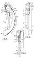
- a spring R1 which has the shape of a V with an obtuse angle.
- a branch 61 of the V has a free end curved in the shape of a hook 71 which cooperates with a radial groove formed in the axis forming a pivot 52 to immobilize the latter.
- the branch 61 substantially rectilinear, crosses a passage 81 formed in the body 48 of the spacer 44. Beyond the apex of the obtuse angle, there is the other branch 91 of the V, substantially rectilinear, which ends at its free end by a part of the folded wire 101 substantially perpendicular to the branch 91.
- the branch 91 is applied against the outer face of the brake lever 50, opposite to that which is in contact with the core 18 of the brake shoe.
- the part 101 folded down at 90 ° penetrates at its end into an orifice 111 formed in the core 18. It will be appreciated that the folded part 101 cooperates, in shear, between the core 18 and the lever 50, and ensures the function of the stop 56 in Figure 1.
- the mounting of the brake of Figure 2 including the mounting spring R1 is very easy. It is produced after threading the spring R1 through the passage 81, by stapling the hook 71 on the pivot 52 followed by the insertion of the part 101 into the orifice 111, or vice versa.
- Disassembly can be carried out in reverse of the assembly described below or, preferably, by driving in the folded part 101 into the orifice 111 by means of a tool acting in thrust.
- the element 46 essentially consists of a screw with which a nut 45 provided with teeth cooperates with which a pawl 47 acts.
- the screw 46 is slidably mounted in the body of the spacer 44. Its head 49, of cylindrical shape, has a hexagonal recess 51 (see FIG. 5) into which a projection 53 of the segment 12 penetrates.
- this projection 53a on segment 14 is held in the hexagonal recess 51 by means of a tension spring 65 anchored by one of its ends in an orifice 67 of the segment 12 and passing diametrically through the screw 46 in the vicinity of the head 49 at its other end.
- FIGS. 6 and 7 show a device according to a second embodiment of the invention.
- the elastic wire spring R2 has two branches 62 and 92 extending substantially in the same plane.
- the branch 62 has at its free end a curved portion 72 in the form of a hook which cooperates with a radial groove of the pivot 52 which it immobilizes axially.
- the branch 62 Before reaching the apex of the angle of the V, the branch 62 enters a passage 82 formed laterally in the spacer 48.
- the free end of the branch 92 comprises, after being folded back 90 ° in the plane of the V , a part 94 terminated by an end 102 folded at 90 ° relative to the plane of the V and which enters an opening 112 formed in the core 18 against which the parts 92 and 94 of the second branch of the spring R2 extend V. It projects beyond this opening 112 to intercept the edge of the lever 50 (for which it constitutes the stop 56 of the brake known in FIG. 1).
- FIGS. 8 and 9 show a device according to a third embodiment of the invention.
- the elastic wire spring R3 has two branches 63 and 93 extending substantially in the same plane.
- the branch 63 has at its free end a curved portion 73 in the form of a hook which cooperates with a radial groove of the pivot 52 which it immobilizes axially.
- the end of the branch 93 comprises, after a 90 ° folding in the plane of the V a portion 96 terminated by an end 103, folded 90 ° relative to the plane of the V, which enters an opening 113 formed in the lever 50.
- the parts 93 and 96 of the second branch of the spring R3 in V extend in a plane parallel to the core 18 and the part folded at 90 °, 113, pressed into the opening 113 of the lever 50 works in shear against the edge of the core 18 to perform the function of the lever 50 rest stop on the core.
- the invention is not limited to the embodiments described, it is understood in particular that it applies perfectly to a drum brake in which the spacer does not include means for taking up wear on the segments.
Landscapes
- Engineering & Computer Science (AREA)
- General Engineering & Computer Science (AREA)
- Mechanical Engineering (AREA)
- Braking Arrangements (AREA)
Applications Claiming Priority (2)
| Application Number | Priority Date | Filing Date | Title |
|---|---|---|---|
| FR8610694 | 1986-07-23 | ||
| FR8610694A FR2602020B1 (fr) | 1986-07-23 | 1986-07-23 | Ressort pour l'assemblage d'un frein a tambour |
Publications (2)
| Publication Number | Publication Date |
|---|---|
| EP0254629A1 true EP0254629A1 (de) | 1988-01-27 |
| EP0254629B1 EP0254629B1 (de) | 1989-09-27 |
Family
ID=9337673
Family Applications (1)
| Application Number | Title | Priority Date | Filing Date |
|---|---|---|---|
| EP87401637A Expired EP0254629B1 (de) | 1986-07-23 | 1987-07-10 | Feder für eine Trommelbremsanordnung |
Country Status (7)
| Country | Link |
|---|---|
| US (1) | US4760897A (de) |
| EP (1) | EP0254629B1 (de) |
| BR (1) | BR8704133A (de) |
| DE (1) | DE3760637D1 (de) |
| ES (1) | ES2011812B3 (de) |
| FR (1) | FR2602020B1 (de) |
| PT (1) | PT85370B (de) |
Families Citing this family (1)
| Publication number | Priority date | Publication date | Assignee | Title |
|---|---|---|---|---|
| DE102014214098B3 (de) * | 2014-07-21 | 2015-12-10 | Saf-Holland Gmbh | Bremssystem |
Citations (7)
| Publication number | Priority date | Publication date | Assignee | Title |
|---|---|---|---|---|
| US2292017A (en) * | 1940-09-26 | 1942-08-04 | Thermo Brakes Corp | Brake adjuster |
| FR2155321A5 (de) * | 1971-09-23 | 1973-05-18 | Girling Ltd | |
| FR2378207A1 (fr) * | 1977-01-25 | 1978-08-18 | Dba | Frein a tambour |
| GB2014673A (en) * | 1978-02-08 | 1979-08-30 | Perrot Bremse Gmbh Deutsche | Spring for a Parking Brake in an Internal Expanding Shoe Brake Assembly |
| FR2514090A1 (fr) * | 1981-10-02 | 1983-04-08 | Volkswagenwerk Ag | Frein a tambour a machoires internes pour vehicules automobiles a dispositif mecanique de rattrapage de jeu de desserrage |
| US4470486A (en) * | 1982-07-26 | 1984-09-11 | General Motors Corporation | Automatic wear adjuster for drum brakes |
| EP0146444A1 (de) * | 1983-11-21 | 1985-06-26 | BENDIX France | Verankerung eines Verstrebungselementes, welches eine Einrichtung zur automatischen Regelung für ein Bremsbackensegment aufweist |
Family Cites Families (6)
| Publication number | Priority date | Publication date | Assignee | Title |
|---|---|---|---|---|
| US3194352A (en) * | 1961-11-08 | 1965-07-13 | Ford Motor Co | Balanced shoe brake |
| GB1191320A (en) * | 1967-08-04 | 1970-05-13 | Girling Ltd | Improvements in Automatic Adjusters for Brakes |
| DE2262926A1 (de) * | 1972-12-22 | 1974-06-27 | Volkswagenwerk Ag | Nachstellvorrichtung fuer innenbackenbremse |
| US4174770A (en) * | 1978-03-03 | 1979-11-20 | Societe Anonyme D.B.A. | Drum brake |
| FR2419431A1 (fr) * | 1978-03-06 | 1979-10-05 | Dba | Amelioration aux freins a tambour |
| US4420486A (en) * | 1981-01-22 | 1983-12-13 | Hokko Chemical Industry Co., Ltd. | Benzoxazolone derivatives, processes for preparation thereof and compositions containing them |
-
1986
- 1986-07-23 FR FR8610694A patent/FR2602020B1/fr not_active Expired
-
1987
- 1987-07-10 EP EP87401637A patent/EP0254629B1/de not_active Expired
- 1987-07-10 ES ES87401637T patent/ES2011812B3/es not_active Expired - Lifetime
- 1987-07-10 DE DE8787401637T patent/DE3760637D1/de not_active Expired
- 1987-07-15 US US07/073,922 patent/US4760897A/en not_active Expired - Fee Related
- 1987-07-21 PT PT85370A patent/PT85370B/pt not_active IP Right Cessation
- 1987-07-22 BR BR8704133A patent/BR8704133A/pt not_active IP Right Cessation
Patent Citations (7)
| Publication number | Priority date | Publication date | Assignee | Title |
|---|---|---|---|---|
| US2292017A (en) * | 1940-09-26 | 1942-08-04 | Thermo Brakes Corp | Brake adjuster |
| FR2155321A5 (de) * | 1971-09-23 | 1973-05-18 | Girling Ltd | |
| FR2378207A1 (fr) * | 1977-01-25 | 1978-08-18 | Dba | Frein a tambour |
| GB2014673A (en) * | 1978-02-08 | 1979-08-30 | Perrot Bremse Gmbh Deutsche | Spring for a Parking Brake in an Internal Expanding Shoe Brake Assembly |
| FR2514090A1 (fr) * | 1981-10-02 | 1983-04-08 | Volkswagenwerk Ag | Frein a tambour a machoires internes pour vehicules automobiles a dispositif mecanique de rattrapage de jeu de desserrage |
| US4470486A (en) * | 1982-07-26 | 1984-09-11 | General Motors Corporation | Automatic wear adjuster for drum brakes |
| EP0146444A1 (de) * | 1983-11-21 | 1985-06-26 | BENDIX France | Verankerung eines Verstrebungselementes, welches eine Einrichtung zur automatischen Regelung für ein Bremsbackensegment aufweist |
Also Published As
| Publication number | Publication date |
|---|---|
| FR2602020B1 (fr) | 1988-10-21 |
| US4760897A (en) | 1988-08-02 |
| ES2011812B3 (es) | 1990-02-16 |
| FR2602020A1 (fr) | 1988-01-29 |
| PT85370B (pt) | 1993-07-30 |
| DE3760637D1 (en) | 1989-11-02 |
| EP0254629B1 (de) | 1989-09-27 |
| BR8704133A (pt) | 1988-04-12 |
| PT85370A (pt) | 1988-07-29 |
Similar Documents
| Publication | Publication Date | Title |
|---|---|---|
| EP0142421B1 (de) | Hebel für mechanische Bedienungsvorrichtung einer Trommelbremse und Trommelbremse mit einem solchen Hebel | |
| FR2517399A1 (fr) | Frein a disque et patin pour un tel frein | |
| FR2500096A1 (fr) | Ressort pour frein a disque | |
| FR2726615A1 (fr) | Dispositif d'actionnement mecanique pour frein a tambour | |
| EP0486341B1 (de) | Mechanisch betätigbare Trommelbremse | |
| EP0734496B1 (de) | Automatisch nachstellbare strebe für eine trommelbremse | |
| EP0002399B1 (de) | Scheibenbremse | |
| EP0069657B1 (de) | Trommelbremse | |
| EP0186537B1 (de) | Scheibenbremse | |
| FR2576379A1 (fr) | Frein a disque a etrier coulissant | |
| EP0254629B1 (de) | Feder für eine Trommelbremsanordnung | |
| EP0125959A1 (de) | Bremsvorrichtung mit mechanischem Antrieb | |
| EP0077726B1 (de) | Trommelbremse und Strebenteil für eine derartige Bremse | |
| WO1996041966A1 (fr) | Frein a disque utilisant un patin sollicite en rotation | |
| EP0087376A1 (de) | Vorrichtung zum Spulen von Textilmaterialien die ein Bremselement zur Stillsetzung des Wickels am Ende des Spulvorganges hat | |
| EP0294286A2 (de) | Scheibenbremsenfeder und mit einer solchen Feder ausgerüstete Scheibenbremse | |
| EP0061961A1 (de) | Trommelbremse mit selbsttätiger Nachstellung | |
| EP0349368B1 (de) | Einstellbare Scheibenbremse | |
| EP0146444B1 (de) | Verankerung eines Verstrebungselementes, welches eine Einrichtung zur automatischen Regelung für ein Bremsbackensegment aufweist | |
| FR2497308A1 (fr) | Frein a tambour a segments interieurs | |
| EP0003452B1 (de) | Trommelbremse | |
| EP0604251B1 (de) | Antriebseinrichtung für die Spielnachstellung einer Trommelbremse | |
| EP0319358A1 (de) | Trommelbremse mit selbsttätiger Nachstellung | |
| FR2704504A1 (fr) | Dispositif de traction tel un levier de commande de frein de stationnement en particulier pour véhicule automobile. | |
| FR2515293A1 (fr) | Dispositif de reglage automatique pour un frein |
Legal Events
| Date | Code | Title | Description |
|---|---|---|---|
| PUAI | Public reference made under article 153(3) epc to a published international application that has entered the european phase |
Free format text: ORIGINAL CODE: 0009012 |
|
| 17P | Request for examination filed |
Effective date: 19870729 |
|
| AK | Designated contracting states |
Kind code of ref document: A1 Designated state(s): DE ES GB IT |
|
| 17Q | First examination report despatched |
Effective date: 19880816 |
|
| GRAA | (expected) grant |
Free format text: ORIGINAL CODE: 0009210 |
|
| ITF | It: translation for a ep patent filed | ||
| AK | Designated contracting states |
Kind code of ref document: B1 Designated state(s): DE ES GB IT |
|
| REF | Corresponds to: |
Ref document number: 3760637 Country of ref document: DE Date of ref document: 19891102 |
|
| GBT | Gb: translation of ep patent filed (gb section 77(6)(a)/1977) | ||
| PLBE | No opposition filed within time limit |
Free format text: ORIGINAL CODE: 0009261 |
|
| STAA | Information on the status of an ep patent application or granted ep patent |
Free format text: STATUS: NO OPPOSITION FILED WITHIN TIME LIMIT |
|
| 26N | No opposition filed | ||
| ITTA | It: last paid annual fee | ||
| PGFP | Annual fee paid to national office [announced via postgrant information from national office to epo] |
Ref country code: GB Payment date: 19960701 Year of fee payment: 10 |
|
| PGFP | Annual fee paid to national office [announced via postgrant information from national office to epo] |
Ref country code: DE Payment date: 19960722 Year of fee payment: 10 |
|
| PGFP | Annual fee paid to national office [announced via postgrant information from national office to epo] |
Ref country code: ES Payment date: 19960729 Year of fee payment: 10 |
|
| PG25 | Lapsed in a contracting state [announced via postgrant information from national office to epo] |
Ref country code: GB Free format text: LAPSE BECAUSE OF NON-PAYMENT OF DUE FEES Effective date: 19970710 |
|
| PG25 | Lapsed in a contracting state [announced via postgrant information from national office to epo] |
Ref country code: ES Free format text: LAPSE BECAUSE OF NON-PAYMENT OF DUE FEES Effective date: 19970711 |
|
| GBPC | Gb: european patent ceased through non-payment of renewal fee |
Effective date: 19970710 |
|
| PG25 | Lapsed in a contracting state [announced via postgrant information from national office to epo] |
Ref country code: DE Free format text: LAPSE BECAUSE OF NON-PAYMENT OF DUE FEES Effective date: 19980401 |
|
| REG | Reference to a national code |
Ref country code: ES Ref legal event code: FD2A Effective date: 20020603 |
|
| PG25 | Lapsed in a contracting state [announced via postgrant information from national office to epo] |
Ref country code: IT Free format text: LAPSE BECAUSE OF NON-PAYMENT OF DUE FEES;WARNING: LAPSES OF ITALIAN PATENTS WITH EFFECTIVE DATE BEFORE 2007 MAY HAVE OCCURRED AT ANY TIME BEFORE 2007. THE CORRECT EFFECTIVE DATE MAY BE DIFFERENT FROM THE ONE RECORDED. Effective date: 20050710 |