EP0254529B1 - Permanent-magnetic material - Google Patents
Permanent-magnetic material Download PDFInfo
- Publication number
- EP0254529B1 EP0254529B1 EP87306435A EP87306435A EP0254529B1 EP 0254529 B1 EP0254529 B1 EP 0254529B1 EP 87306435 A EP87306435 A EP 87306435A EP 87306435 A EP87306435 A EP 87306435A EP 0254529 B1 EP0254529 B1 EP 0254529B1
- Authority
- EP
- European Patent Office
- Prior art keywords
- constituent
- amount
- element selected
- range
- permanent
- Prior art date
- Legal status (The legal status is an assumption and is not a legal conclusion. Google has not performed a legal analysis and makes no representation as to the accuracy of the status listed.)
- Expired - Lifetime
Links
Images
Classifications
-
- H—ELECTRICITY
- H01—ELECTRIC ELEMENTS
- H01F—MAGNETS; INDUCTANCES; TRANSFORMERS; SELECTION OF MATERIALS FOR THEIR MAGNETIC PROPERTIES
- H01F1/00—Magnets or magnetic bodies characterised by the magnetic materials therefor; Selection of materials for their magnetic properties
- H01F1/01—Magnets or magnetic bodies characterised by the magnetic materials therefor; Selection of materials for their magnetic properties of inorganic materials
- H01F1/03—Magnets or magnetic bodies characterised by the magnetic materials therefor; Selection of materials for their magnetic properties of inorganic materials characterised by their coercivity
- H01F1/032—Magnets or magnetic bodies characterised by the magnetic materials therefor; Selection of materials for their magnetic properties of inorganic materials characterised by their coercivity of hard-magnetic materials
- H01F1/04—Magnets or magnetic bodies characterised by the magnetic materials therefor; Selection of materials for their magnetic properties of inorganic materials characterised by their coercivity of hard-magnetic materials metals or alloys
- H01F1/047—Alloys characterised by their composition
- H01F1/053—Alloys characterised by their composition containing rare earth metals
- H01F1/055—Alloys characterised by their composition containing rare earth metals and magnetic transition metals, e.g. SmCo5
- H01F1/057—Alloys characterised by their composition containing rare earth metals and magnetic transition metals, e.g. SmCo5 and IIIa elements, e.g. Nd2Fe14B
- H01F1/0571—Alloys characterised by their composition containing rare earth metals and magnetic transition metals, e.g. SmCo5 and IIIa elements, e.g. Nd2Fe14B in the form of particles, e.g. rapid quenched powders or ribbon flakes
- H01F1/0575—Alloys characterised by their composition containing rare earth metals and magnetic transition metals, e.g. SmCo5 and IIIa elements, e.g. Nd2Fe14B in the form of particles, e.g. rapid quenched powders or ribbon flakes pressed, sintered or bonded together
- H01F1/0577—Alloys characterised by their composition containing rare earth metals and magnetic transition metals, e.g. SmCo5 and IIIa elements, e.g. Nd2Fe14B in the form of particles, e.g. rapid quenched powders or ribbon flakes pressed, sintered or bonded together sintered
-
- H—ELECTRICITY
- H01—ELECTRIC ELEMENTS
- H01F—MAGNETS; INDUCTANCES; TRANSFORMERS; SELECTION OF MATERIALS FOR THEIR MAGNETIC PROPERTIES
- H01F1/00—Magnets or magnetic bodies characterised by the magnetic materials therefor; Selection of materials for their magnetic properties
- H01F1/01—Magnets or magnetic bodies characterised by the magnetic materials therefor; Selection of materials for their magnetic properties of inorganic materials
- H01F1/03—Magnets or magnetic bodies characterised by the magnetic materials therefor; Selection of materials for their magnetic properties of inorganic materials characterised by their coercivity
- H01F1/032—Magnets or magnetic bodies characterised by the magnetic materials therefor; Selection of materials for their magnetic properties of inorganic materials characterised by their coercivity of hard-magnetic materials
- H01F1/04—Magnets or magnetic bodies characterised by the magnetic materials therefor; Selection of materials for their magnetic properties of inorganic materials characterised by their coercivity of hard-magnetic materials metals or alloys
- H01F1/047—Alloys characterised by their composition
- H01F1/053—Alloys characterised by their composition containing rare earth metals
- H01F1/055—Alloys characterised by their composition containing rare earth metals and magnetic transition metals, e.g. SmCo5
- H01F1/057—Alloys characterised by their composition containing rare earth metals and magnetic transition metals, e.g. SmCo5 and IIIa elements, e.g. Nd2Fe14B
Definitions
- This invention relates to an intermetallic compound type permanent-magnet material comprising a rare earth element and Co, and particularly to an intermetallic compound type permanent-magnet material comprising a rare earth element and Co and possessing an improved sintering property and to a method for the production thereof.
- intermetallic compound type alloys which are formed by combining a rare earth element combination of Sm and Ce with Co and Fe, Cu, etc. have been known as permanent-magnet materials excelling in residual flux density and coercive force.
- intermetallic compound type alloys which incorporate therein B and Ti, V, Zr, etc. besides the elements mentioned above for the purpose of acquiring further improved coercive force have also been known (specification of Japanese Patent Application Disclosure SHO 55(1980)-115,304).
- Japanese Patent Application Disclosure SHO 56(1981)-47,540 discloses a permanent-magnet material produced by the combination of Zr and at least one element selected from among Ca, S, P, Mg, and B.
- the inventors continued a study in an effort to eliminate the drawbacks suffered by the conventional permanent-magnet materials as described above. They have consequently found that the permanent-magnet materials formed of intermetallic type compound alloys of the class under discussion are enabled by addition thereto of a minute amount of B to permit coexistence of solid and liquid phases in widened regions and acquire notable improvement in their sintering property.
- the present invention aims to provide a permanent-magnet material which permits coexistence of liquid and solid phases in a wide region and enables sintering conditions warranting impartation of highly desirable magnetic characteristics to be selected in wide ranges.
- the permanent-magnet materials of the present invention has a composition represented by the following formula: R(Co 1-X-Y- ⁇ - ⁇ Fe X Cu y M ⁇ M' ⁇ ) A (wherein X, Y, ⁇ , ⁇ , and A respectively represent the following numbers: 0.01 ⁇ X, 0.02 ⁇ Y ⁇ 0.25, 0.001 ⁇ ⁇ ⁇ 0.15, 0.0001 ⁇ ⁇ ⁇ 0.001, and 6.0 ⁇ A ⁇ 8.3, providing that the amount of Fe to be added should be less than 15 % by weight, based on the total amount of the composition, and R, M, and M ⁇ respectively represent the following constituents:
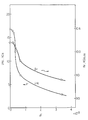
- the figure is a graph showing curves of residual flux density, Br, and coercive force, "iHc", as the functions of the amount of boron, B, ⁇ , obtained of test specimens of a composition, Sm(Co 0.70- ⁇ Fe 0.20 Cu 0.07 Zr 0.03 B ⁇ ) 7.8 .
- the permanent magnet of this invention is produced by preparing metallic elements, i.e. component raw materials, in the proportions indicated by the aforementioned formula, melting and casting the raw materials in an inert atmosphere thereby producing an ingot, coarsely crushing this ingot into coarse particles, then finely comminuting the coarse particles into fine particles not more than 10 ⁇ m in diameter, orienting a mass of the finely comminuted mixture in a magnetic field, forming the oriented mass of mixture as compressed thereby giving rise to a shaped article, sintering the shaped article in an inert atmosphere at a temperature in the range of 1,180°C to 1,230°C for a period in the range of 3 to 6 hours, further subjecting the sintered shaped article to a solution treatment at a temperature in the range of 1,150°C to 1,210°C for a period in the range of 3 to 12 hours, subsquently allowing the resultant shaped article to stand at a temperature in the range of 700°C to 900°C for a period in the
- the permanent magnet according to the present invention is such that it acquires highly desirable magnetic characteristics even when the shaped article, in the aforementioned step of sintering, is sintered at a temperature 10°C to 20°C lower than "the temperature of loss by melting" (The temperature at which the article can not retain required shape because the amount of liquid phase thereof becomes more than certain level in the sintering step).
- the permanent magnet can be produced with well balanced characteristics.
- the permanent-magnet material of the present invention can be produced by mixing a powdered alloy having a composition of the formula: R(Co 1-X-Y- ⁇ Fe X Cu Y M ⁇ ) A (I) and a powdered alloy having a composition of the formula: R(Co 1-X-Y- ⁇ - ⁇ Fe X Cu Y M ⁇ M ⁇ ⁇ ) A (II) in a prescribed ratio, forming the resulting mixture in a magnetic field in a stated shape, and then heat treating the resultant shaped article at a temperature not exceeding the melting point.
- the mixing ratio of the powdered alloy represented by the formula (I) and the powdered alloy represented by the formula (II) falls in the range of 1 : 1 to 1,000 : 1.
- the element B which is incorporated in a very minute amount functions to lower notably the melting point of the grain boundaries and the element B so incorporated undergoes solid solution with the mother phase only to a nominal extent and, therefore, segregates itself in the grain boundaries and brings about a minimal effect on the magnetic characteristics of the permanent magnet.
- the resultant mixture was melted and cast in a high-frequency furnace, then coarsely crushed with a jaw crusher, and further comminuted finely with a jet mill to obtain a powdered mixture having particle diameters of 3 to 10 ⁇ m.
- This powdered mixture was press formed in a magnetic field of 10 KOe under a pressure of 2 tons/cm2 to obtain a rectangular slid measuring 40 mm ⁇ 40 mm ⁇ 10 mm.
- This shaped article was sintered in an industrial grade furnace at a temperature in the range of 1,150°C to 1,180°C for a period in the range of 3 to 6 hours, surther subjected to a solution treatment at a temperature in the range of 1,120°C to 1,150°C for a period in the range of 3 to 12 hours, subsequently left aging at a temperature in the range of 700°C to 900°C for a period in the range of 4 to 12 hours, and thereafter cooled as controlled in a furnace.
- a permanent-magnet material was obtained as aimed at.
- a permanent-magnet material was produced by faithfully following the procedure of Example 1, excepting the molten material composed of the aforementioned components excluded B.
- the permanent-magnet material was allowed to acquire the expected characteristics only when the work of sintering was carried out at a temperature 2°C lower than the temperature of loss by melting, with the temperature controlled rigidly accurately within ⁇ 1°C.
- the magnetic characteristics of the product were heavily dispersed by relative position of sintering.
- the magnetic characteristics of the product of Example 1 and those of the product of the comparative experiment are shown in the Table.
- the resultant powdered mixture was formed under the same conditions.
- the resultant shaped article was sintered and subjected to a solution treatment and left aging in an industrial grade furnace under the same conditions as in Example 1.
- the permanent-magnet material consequently obtained acquired highly desirable magnetic characteristics even when the shaped article, during the step of sintering, was sintered in a temperature range 10°C to 40°C lower than the temperature of loss by melting. These magnetic characteristics were equivalent to those obtained when there was used a single powdered alloy of a composition contemplated by the invention.
- the resultant powdered mixture was formed under the same conditions as in Example 1, sintered in an industrial grade furnace at a temperature in the range of 1,170°C to 1,190°C, then subjected to a solution treatment at a temperature in the range of 1,150°C to 1,170°C, subsequently left cooling at a temperature in the range of 500°C to 600°C, and subjected to an aging treatment.
- the permanent-magnet material consequently obtained acquired highly desirable magnetic characteristics even when the shaped article, during the step of sintering, was sintered in a temperature zone 0°C to 20°C lower than the proper sintering temperature of the alloy of the composition (I ⁇ ) containing no boron, B.
- the magnetic characteristics were equivalent to those obtained when there was used a single powdered alloy of a composition contemplated by this invention.
- the permanent-magnet material of the present invention is enabled, by addition thereto of a minute amount of B, to acquire a conspicuously improved sintering property and enjoy notable improvements in productivity and yield with respect to the sintering performed in an industrial grade furnace.
Landscapes
- Chemical & Material Sciences (AREA)
- Crystallography & Structural Chemistry (AREA)
- Inorganic Chemistry (AREA)
- Engineering & Computer Science (AREA)
- Power Engineering (AREA)
- Hard Magnetic Materials (AREA)
- Control Of Positive-Displacement Pumps (AREA)
- Powder Metallurgy (AREA)
Description
- This invention relates to an intermetallic compound type permanent-magnet material comprising a rare earth element and Co, and particularly to an intermetallic compound type permanent-magnet material comprising a rare earth element and Co and possessing an improved sintering property and to a method for the production thereof.
- Heretofore, the intermetallic compound type alloys which are formed by combining a rare earth element combination of Sm and Ce with Co and Fe, Cu, etc. have been known as permanent-magnet materials excelling in residual flux density and coercive force.
- The intermetallic compound type alloys which incorporate therein B and Ti, V, Zr, etc. besides the elements mentioned above for the purpose of acquiring further improved coercive force have also been known (specification of Japanese Patent Application Disclosure SHO 55(1980)-115,304).
- Japanese Patent Application Disclosure SHO 56(1981)-47,540 discloses a permanent-magnet material produced by the combination of Zr and at least one element selected from among Ca, S, P, Mg, and B.
- These permanent-magnet materials, however, have the disadvantage that their regions permitting coexistence of liquid and solid phases are narrow and their sintering conditions permitting impartation of highly desirable magnetic characteristics are restricted to extremely narrow ranges as represented by the temperature range of ±1°C to 2°C.
- If a permanent-magnet material which has sintering conditions permitting impartation of highly satisfactory magnetic characteristics in such a narrow range as mentioned above is produced with an industrial grade furnace of popular use, since this furnace has a large inner temperature gradient, the produced permanent-magnet material is liable to acquire inferior characteristics and the production itself suffers from a poor yield.
- The inventors continued a study in an effort to eliminate the drawbacks suffered by the conventional permanent-magnet materials as described above. They have consequently found that the permanent-magnet materials formed of intermetallic type compound alloys of the class under discussion are enabled by addition thereto of a minute amount of B to permit coexistence of solid and liquid phases in widened regions and acquire notable improvement in their sintering property.
- The present invention, having originated in the finding mentioned above, aims to provide a permanent-magnet material which permits coexistence of liquid and solid phases in a wide region and enables sintering conditions warranting impartation of highly desirable magnetic characteristics to be selected in wide ranges.
- Specifically, the permanent-magnet materials of the present invention has a composition represented by the following formula:
R(Co1-X-Y-α-βFeXCuyMα M'β)A
(wherein X, Y, α, β, and A respectively represent the following numbers:
0.01 ≦ X, 0.02 ≦ Y ≦ 0.25, 0.001 ≦ α ≦ 0.15, 0.0001 ≦ β ≦ 0.001, and 6.0 ≦ A ≦ 8.3,
providing that the amount of Fe to be added should be less than 15 % by weight, based on the total amount of the composition, and R, M, and Mʹ respectively represent the following constituents: - R:
- At least one element selected from the group of rare earth elements,
- M:
- At least one element selected from the group consisting of Ti, Zr, Hf, Nb, V, and Ta, and
- Mʹ:
- B or B + Si)
- The characteristics of this invention are discerned clearly from a figure. To be more specific, the figure is a graph showing curves of residual flux density, Br, and coercive force, "iHc", as the functions of the amount of boron, B, β, obtained of test specimens of a composition,
Sm(Co0.70-βFe0.20Cu0.07Zr0.03Bβ)7.8.
- In the present invention, the numerical values of X, Y, α, β, and A in the formula of composition are defined as mentioned above for the following reason.
- 1) 0.01 = X;
An increase in the amount of Fe is found to bring about an improvement in residual flux density. If the amount of Fe to be added increases to exceed 15 % by weight, based on the total amount of composition, the mixture of component raw materials is finely comminuted only with great difficulty. If X is less than 0.01 (X < 0.01), no sufficiently high residual flux density is obtained. - 2) 0.02 ≦ Y ≦ 0.25;
If the relative amount of copper, Y, is less than 0.02 (0.02 > Y), the reaction of two-phase decomposition proceeds with difficulty.
If this amount is more than 0.25 (0.25 < Y), the residual flux density is unduly low and the thermal stability is insufficient. - 3) 0.001 ≦ α ≦ 0.15;
The constituent M is at least one element to be selected from among Ti, Zr, Hf, Nb, V, and Ta, preferably from among Ti, Zr, and Hf. If α is less than 0.001 (0.001 > α ), no sufficient coercive force is obtained. If α is more than 0.15 (0.15 <α), the residual flux density is not sufficient. - 4) 0.0001 ≦ β ≦ 0.001;
The constituent Mʹ is either B or B + Si. Particularly, the amount of boron, B, to be incorporated has a conspicuous effect on the magnetic characteristics of a magnet to be produced. The figure shows the curves of residual flux density, Br, and coercive force, "iHc", as the functions of the amount of B, β, obtained of test specimens having a typical composition,
Sm(Co0.70-βFe0.20Cu0.07Zr0.03Bβ)7.8.
It is noted from the figure that both Br and iHc are varied very largely by a minute change in the amount of boron, B and that they both decrease with the increasing amount of B. Particularly, both Br and "iHc" sharply decrease when the numerical value of β increases beyond 1 x 10⁻³.
It has been established experimentally, on the other hand, that the effect in the improvement of sintering property suddenly ceases to exist when the relative amount of B to be added decreases below 1 x 10⁻⁴. - 5) 6.0 ≦ A ≦ 8.3
If A is less than 6.0 (6.0 > A), no sufficient coercive force Br is obtained. If A is more than 8.3 (8.3 < A), the composition gives rise to dendrite, an undesirable ingredient for the permanent magnet aimed at. - The permanent magnet of this invention is produced by preparing metallic elements, i.e. component raw materials, in the proportions indicated by the aforementioned formula, melting and casting the raw materials in an inert atmosphere thereby producing an ingot, coarsely crushing this ingot into coarse particles, then finely comminuting the coarse particles into fine particles not more than 10 µm in diameter, orienting a mass of the finely comminuted mixture in a magnetic field, forming the oriented mass of mixture as compressed thereby giving rise to a shaped article, sintering the shaped article in an inert atmosphere at a temperature in the range of 1,180°C to 1,230°C for a period in the range of 3 to 6 hours, further subjecting the sintered shaped article to a solution treatment at a temperature in the range of 1,150°C to 1,210°C for a period in the range of 3 to 12 hours, subsquently allowing the resultant shaped article to stand at a temperature in the range of 700°C to 900°C for a period in the range of 4 to 12 hours, and left aging in a furnace under controlled cooling.
- The permanent magnet according to the present invention is such that it acquires highly desirable magnetic characteristics even when the shaped article, in the aforementioned step of sintering, is sintered at a
temperature 10°C to 20°C lower than "the temperature of loss by melting" (The temperature at which the article can not retain required shape because the amount of liquid phase thereof becomes more than certain level in the sintering step). Thus, even in a furnace such as the industrial grade furnace which has a relatively wide range of temperature control, the permanent magnet can be produced with well balanced characteristics. - Further, the permanent-magnet material of the present invention can be produced by mixing a powdered alloy having a composition of the formula:
R(Co1-X-Y-αFeXCuYMα)A (I)
and a powdered alloy having a composition of the formula:
R(Co1-X-Y-α-βFeXCuYMαMʹβ)A (II)
in a prescribed ratio, forming the resulting mixture in a magnetic field in a stated shape, and then heat treating the resultant shaped article at a temperature not exceeding the melting point. - Suitably the mixing ratio of the powdered alloy represented by the formula (I) and the powdered alloy represented by the formula (II) falls in the range of 1 : 1 to 1,000 : 1.
- Entirely the same effect as described above is obtained when boron, B is added in a prescribed proportion during the melting of the other component raw materials instead of simultaneously mixing all the component raw materials.
- In the permanent-magnet material of the present invention, the element B which is incorporated in a very minute amount functions to lower notably the melting point of the grain boundaries and the element B so incorporated undergoes solid solution with the mother phase only to a nominal extent and, therefore, segregates itself in the grain boundaries and brings about a minimal effect on the magnetic characteristics of the permanent magnet.
- Now, the present invention will be descried specifically below with reference to working examples.
- Pertinent raw materials in a molten state were combined in proportions calculated to give a composition of the following formula:
(Sm0.6Co0.4)(Co0.72-0.0008Fe0.20Cu0.06Zr0.02B0.00018)7.45
- The resultant mixture was melted and cast in a high-frequency furnace, then coarsely crushed with a jaw crusher, and further comminuted finely with a jet mill to obtain a powdered mixture having particle diameters of 3 to 10 µm. This powdered mixture was press formed in a magnetic field of 10 KOe under a pressure of 2 tons/cm² to obtain a rectangular slid measuring 40 mm × 40 mm × 10 mm. This shaped article was sintered in an industrial grade furnace at a temperature in the range of 1,150°C to 1,180°C for a period in the range of 3 to 6 hours, surther subjected to a solution treatment at a temperature in the range of 1,120°C to 1,150°C for a period in the range of 3 to 12 hours, subsequently left aging at a temperature in the range of 700°C to 900°C for a period in the range of 4 to 12 hours, and thereafter cooled as controlled in a furnace. Thus, a permanent-magnet material was obtained as aimed at.
- Separately, for comparison, a permanent-magnet material was produced by faithfully following the procedure of Example 1, excepting the molten material composed of the aforementioned components excluded B. In this case, the permanent-magnet material was allowed to acquire the expected characteristics only when the work of sintering was carried out at a temperature 2°C lower than the temperature of loss by melting, with the temperature controlled rigidly accurately within ±1°C. When the work of sintering was carried out in an industrial grade furnace, the magnetic characteristics of the product were heavily dispersed by relative position of sintering. The magnetic characteristics of the product of Example 1 and those of the product of the comparative experiment are shown in the Table.

- A powdered alloy of a composition:
(Sm0.60Ce0.40)(Co0.72Fe0.20Cu0.06Zr0.02)7.45 (Iʹ)
having particle diameters of 3 to 10 um and prepared by following the procedure of Example 1 and a powdered alloy of a composition:
(Sm0.60Ce0.40)(Co0.72-0.072Fe0.20Cu0.06Zr0.02B0.072)7.45 (IIʹ)
were mixed in a ratio of 400 : 1. The resultant powdered mixture was formed under the same conditions. The resultant shaped article was sintered and subjected to a solution treatment and left aging in an industrial grade furnace under the same conditions as in Example 1. - The permanent-magnet material consequently obtained acquired highly desirable magnetic characteristics even when the shaped article, during the step of sintering, was sintered in a
temperature range 10°C to 40°C lower than the temperature of loss by melting. These magnetic characteristics were equivalent to those obtained when there was used a single powdered alloy of a composition contemplated by the invention. - A powdered alloy of a composition:
Sm(Co0.71Fe0.14Cu0.13Ti0.02)6.99 (I")
having particle diameters of 3 to 10 um and prepared by following the procedure of Example 1 and a powdered alloy of a composition:
Sm(Co0.71-0.072Fe0.14Cu0.13Ti0.02B0.072)6.99 (II")
were mixed at a ratio of 400 : 1. The resultant powdered mixture was formed under the same conditions as in Example 1, sintered in an industrial grade furnace at a temperature in the range of 1,170°C to 1,190°C, then subjected to a solution treatment at a temperature in the range of 1,150°C to 1,170°C, subsequently left cooling at a temperature in the range of 500°C to 600°C, and subjected to an aging treatment. - The permanent-magnet material consequently obtained acquired highly desirable magnetic characteristics even when the shaped article, during the step of sintering, was sintered in a temperature zone 0°C to 20°C lower than the proper sintering temperature of the alloy of the composition (Iʺ) containing no boron, B. The magnetic characteristics were equivalent to those obtained when there was used a single powdered alloy of a composition contemplated by this invention.
- The foregoing working examples have been described as representing cases using B as the constituent Mʹ. This invention is not limited to those working examples. The same effect as described above can be obtained in cases using B + Si in the place of B. Further, the same effect can be obtained also in cases using elements other than those indicated in the foregoing working examples as the constituent M.
- The permanent-magnet material of the present invention is enabled, by addition thereto of a minute amount of B, to acquire a conspicuously improved sintering property and enjoy notable improvements in productivity and yield with respect to the sintering performed in an industrial grade furnace.
Claims (9)
- A permanent-magnet material having a composition represented by the following formula;
R(Co1-X-Y-α-βFeXCuYMαMʹβ)A
wherein X, Y, α, β, and A respectively represent the following numbers:
0.01 ≦ X, 0.02 ≦ Y ≦ 0.25, 0.001 ≦ α ≦ 0.15, 0.0001 ≦ β ≦ 0.001, and 6.0 ≦ A ≦ 8.3,
providing that the amount of Fe to be added should be less than 15 % by weight, based on the total amount of the composition, and R, M, and Mʹ respectively represent the following constituents:R: At last one element selected from the group of rare earth elements,M: At least one element selected from the group consisting of Ti, Zr, Hf, Nb, V, and Ta, andMʹ: B or B + Si. - The permanent-magnet material according to claim 1, wherein the amount of the constituent, Sm and/or Ce, is not less than 80% by weight, based on the total amount of the constituent, R.
- The permanent-magnet material according to claim 1, wherein the constituent M is at least one element selected from among Ti, Zr, and Hf.
- A method for the production of a permanent-magnet material, characterized by combining pertinent metallic elements as component raw materials in proportions indicated by the following formula:
R(Co1-X-Y-α-β FeXCuYMα Mʹβ)A
wherein X, Y, α , β, and A respectively represent the following numbers:
0.01 ≦ X, 0.02 ≦ Y ≦ 0.25, 0.001 ≦ α ≦ 0.15, 0.0001 ≦ β ≦ 0.001, and 6.0 ≦ A ≦ 8.3,
providing that the amount of Fe to be added should be less than 15% by weight, based on the total amount of the composition, and R, M, and Mʹ respectively represent the following constituents:R: At last one element selected from the group of rare earth elementsM: At least one element selected from the group consisting of Ti, Zr, Hf, Nb, V, and Ta, andMʹ: B or B + Si,melting and casting the resultant mixture in an inert atmosphere thereby obtaining an ingot, coarsely crushing said ingot into coarse particles, finely comminuting said coarse particles into fine particles having particle diameters of not more than 10 µm, orienting a mass of said finely comminuted mixture in a magnetic field, then forming said mass of mixture as compressed thereby obtaining a shaped article, sintering said shaped article in an inert atmosphere at a temperature in the range of 1,150°C to 1,230°C for a period in the range of 3 to 6 hours, subjecting the sintered shaped article to a solution treatment at a temperature in the range of 1,120°C to 1,210°C for a period in the range of 3 to 12 hours, subsequently keeping the resultant shaped article at a temperature in the range of 750°C to 850°C for a period in the range of 4 to 12 hours, and thereafter aging the shaped article by cooling. - The method according to claim 4, wherein the amount of the constituent, Sm and/or Ce, is not less than 80 % by weight, based on the total amount of the constituent, R.
- The method according to claim 4, wherein the constituent M is at least one element selected from among Ti, Zr, and Hf.
- A method for the production of a permanent-magnet material, comprising the steps of mixing a powdered alloy of a composition represented by the formula:
R(Co1-X-Y-αFeXCuYMα)A
and a powdered alloy of a composition represented by the formula:
R(Co1-X-Y-α-β,FeXCuYMαMʹβʹ)A
in a ratio falling in the range of 1 : 1 to 1,000 : 1, thereby producing a mixture of a composition represented by the formula:
R(Co1-X-Y-α-βFeXCuYMαMʹβ)A
wherein, X, Y, α, β, and A respectively represent the following numbers
0.01 ≦ X, 0.02 ≦ Y ≦ 0.25, 0.001 ≦ α ≦ 0.15, 0.0001 ≦ β ≦ 0.001, 6.0 ≦ A ≦ 8.3, and 2β =βʹ,
providing that the amount of Fe to be added should be less than 15 % by weight, based on the total amount of the composition, and R, M, and Mʹ respectively represent the following constituents:R: At least one element selected from the group of rare earth elements,M: At least one element selected from the group consisting of Ti, Zr, Hf, Nb, V, and Ta, andMʹ: B or B + Si,forming said mixture in a magnetic field under pressure thereby obtaining a shaped article, and sintering said shaped article at a temperature 0 C° to 40°C lower than the temperature of loss by melting, the temperature at which the article can not retain required shape because the amount of liquid phase thereof becomes more than certain level in the sintering step. - The method according to claim 7, wherein the amount of the constituent, Sm and/or Ce, is not less than 80 % by weight, based on the total amount of the constituent, R.
- The method according to claim 7, wherein the constituent M is at least one element selected from among Ti, Zr, and Hf.
Applications Claiming Priority (2)
| Application Number | Priority Date | Filing Date | Title |
|---|---|---|---|
| JP173200/86 | 1986-07-23 | ||
| JP61173200A JPS6328844A (en) | 1986-07-23 | 1986-07-23 | Permanent magnet material |
Publications (3)
| Publication Number | Publication Date |
|---|---|
| EP0254529A2 EP0254529A2 (en) | 1988-01-27 |
| EP0254529A3 EP0254529A3 (en) | 1989-08-23 |
| EP0254529B1 true EP0254529B1 (en) | 1993-03-10 |
Family
ID=15955961
Family Applications (1)
| Application Number | Title | Priority Date | Filing Date |
|---|---|---|---|
| EP87306435A Expired - Lifetime EP0254529B1 (en) | 1986-07-23 | 1987-07-21 | Permanent-magnetic material |
Country Status (5)
| Country | Link |
|---|---|
| US (1) | US4734131A (en) |
| EP (1) | EP0254529B1 (en) |
| JP (1) | JPS6328844A (en) |
| KR (1) | KR900006194B1 (en) |
| DE (1) | DE3784575T2 (en) |
Families Citing this family (19)
| Publication number | Priority date | Publication date | Assignee | Title |
|---|---|---|---|---|
| EP0248665B1 (en) * | 1986-06-06 | 1994-05-18 | Seiko Instruments Inc. | Rare earth-iron magnet and method of making same |
| JPH01225101A (en) * | 1988-03-04 | 1989-09-08 | Shin Etsu Chem Co Ltd | Rare earth permanent magnet |
| JP2787580B2 (en) * | 1988-10-06 | 1998-08-20 | 眞人 佐川 | Nd-Fe-B based sintered magnet with excellent heat treatment |
| US4911882A (en) * | 1989-02-08 | 1990-03-27 | Sps Technologies, Inc. | Process for producing permanent magnets |
| JP2774372B2 (en) * | 1990-09-20 | 1998-07-09 | 三菱製鋼株式会社 | Permanent magnet powder |
| GB9022033D0 (en) * | 1990-10-10 | 1990-11-21 | Lee Victor C | A method of making a material with permanent magnetic properties |
| DE69200130T2 (en) * | 1991-03-27 | 1994-09-22 | Toshiba Kawasaki Kk | Magnetic material. |
| CN1035700C (en) * | 1992-07-07 | 1997-08-20 | 上海跃龙有色金属有限公司 | Rare-earth magnetic alloy powder and its processing method |
| US6332933B1 (en) | 1997-10-22 | 2001-12-25 | Santoku Corporation | Iron-rare earth-boron-refractory metal magnetic nanocomposites |
| CN1265401C (en) | 1998-07-13 | 2006-07-19 | 株式会社三德 | Methods of making nanocomposite magnetic materials and methods of making bonded magnets |
| WO2004046409A2 (en) * | 2002-11-18 | 2004-06-03 | Iowa State University Research Foundation, Inc. | Permanent magnet alloy with improved high temperature performance |
| US6979409B2 (en) * | 2003-02-06 | 2005-12-27 | Magnequench, Inc. | Highly quenchable Fe-based rare earth materials for ferrite replacement |
| US20100056290A1 (en) * | 2008-08-27 | 2010-03-04 | Byron Smith | Detachable Putter Head |
| JP5107198B2 (en) * | 2008-09-22 | 2012-12-26 | 株式会社東芝 | PERMANENT MAGNET, PERMANENT MAGNET MANUFACTURING METHOD, AND MOTOR USING THE SAME |
| US8821650B2 (en) * | 2009-08-04 | 2014-09-02 | The Boeing Company | Mechanical improvement of rare earth permanent magnets |
| JP6129813B2 (en) * | 2014-12-05 | 2017-05-17 | 株式会社東芝 | Motor or generator and car |
| JP6129812B2 (en) * | 2014-12-05 | 2017-05-17 | 株式会社東芝 | permanent magnet |
| CN105931776B (en) * | 2016-05-31 | 2017-09-08 | 宁波宁港永磁材料有限公司 | A kind of preparation method of high-performance samarium cobalt permanent magnet body |
| CN106653264B (en) * | 2016-11-28 | 2019-05-10 | 宁波科星材料科技有限公司 | A kind of preparation method of samarium cobalt-based composite magnetic material and samarium cobalt-based composite magnetic material |
Family Cites Families (14)
| Publication number | Priority date | Publication date | Assignee | Title |
|---|---|---|---|---|
| US3874938A (en) * | 1971-04-06 | 1975-04-01 | Int Nickel Co | Hot working of dispersion-strengthened heat resistant alloys and the product thereof |
| US4030946A (en) * | 1976-04-13 | 1977-06-21 | Carpenter Technology Corporation | Eliminating prior particle boundary delineation |
| US4104787A (en) * | 1977-03-21 | 1978-08-08 | General Motors Corporation | Forming curved wafer thin magnets from rare earth-cobalt alloy powders |
| JPS55115304A (en) * | 1979-02-28 | 1980-09-05 | Daido Steel Co Ltd | Permanent magnet material |
| JPS5647542A (en) * | 1979-09-27 | 1981-04-30 | Hitachi Metals Ltd | Alloy for permanent magnet |
| JPS5647540A (en) * | 1979-09-27 | 1981-04-30 | Hitachi Metals Ltd | Alloy for permanent magnet |
| JPS57120307A (en) * | 1981-01-19 | 1982-07-27 | Seiko Epson Corp | Rare earth cobalt permanent magnet |
| JPS57141901A (en) * | 1981-02-26 | 1982-09-02 | Mitsubishi Steel Mfg Co Ltd | Permanent magnet powder |
| JPS5822351A (en) * | 1981-08-04 | 1983-02-09 | Seiko Epson Corp | Rare earth metal-cobalt permanent magnet |
| JPS59153859A (en) * | 1983-02-23 | 1984-09-01 | Daido Steel Co Ltd | Magnet alloy |
| US4597938A (en) * | 1983-05-21 | 1986-07-01 | Sumitomo Special Metals Co., Ltd. | Process for producing permanent magnet materials |
| US4601875A (en) * | 1983-05-25 | 1986-07-22 | Sumitomo Special Metals Co., Ltd. | Process for producing magnetic materials |
| US4585473A (en) * | 1984-04-09 | 1986-04-29 | Crucible Materials Corporation | Method for making rare-earth element containing permanent magnets |
| US4678634A (en) * | 1985-04-18 | 1987-07-07 | Shin-Etsu Chemical Co., Ltd. | Method for the preparation of an anisotropic sintered permanent magnet |
-
1986
- 1986-07-23 JP JP61173200A patent/JPS6328844A/en active Granted
-
1987
- 1987-07-21 US US07/075,996 patent/US4734131A/en not_active Expired - Lifetime
- 1987-07-21 DE DE8787306435T patent/DE3784575T2/en not_active Expired - Lifetime
- 1987-07-21 EP EP87306435A patent/EP0254529B1/en not_active Expired - Lifetime
- 1987-07-23 KR KR1019870008020A patent/KR900006194B1/en not_active Expired
Also Published As
| Publication number | Publication date |
|---|---|
| DE3784575T2 (en) | 1993-06-17 |
| KR880002201A (en) | 1988-04-29 |
| US4734131A (en) | 1988-03-29 |
| DE3784575D1 (en) | 1993-04-15 |
| EP0254529A3 (en) | 1989-08-23 |
| KR900006194B1 (en) | 1990-08-25 |
| EP0254529A2 (en) | 1988-01-27 |
| JPS6328844A (en) | 1988-02-06 |
| JPH0322457B2 (en) | 1991-03-26 |
Similar Documents
| Publication | Publication Date | Title |
|---|---|---|
| EP0254529A2 (en) | Permanent-magnetic material | |
| EP1014392B9 (en) | Rare earth/iron/boron-based permanent magnet alloy composition | |
| US5674327A (en) | Alloy ingot for permanent magnet, anisotropic powders for permanent magnet, method for producing same and permanent magnet | |
| KR900006193B1 (en) | Manufacturing method of neodymium-iron-boron permanent magnet | |
| US4047982A (en) | Permanent magnet and process for producing the same | |
| EP0517179B1 (en) | Method of making two phase Rare Earth permanent magnets | |
| EP0632471B1 (en) | Process of preparing a permanent magnet containing rare earth metal, boron and iron | |
| US4213803A (en) | R2 Co17 Rare type-earth-cobalt, permanent magnet material and process for producing the same | |
| US4221613A (en) | Rare earth-cobalt system permanent magnetic alloys and method of preparing same | |
| EP0595477A1 (en) | Method of manufacturing powder material for anisotropic magnets and method of manufacturing magnets using the powder material | |
| US5690752A (en) | Permanent magnet containing rare earth metal, boron and iron | |
| US4210471A (en) | Permanent magnet material and process for producing the same | |
| EP0069362B1 (en) | Permanent magnet | |
| EP0413496A1 (en) | Titanium alloy and method of production | |
| JPS5911641B2 (en) | Bonded permanent magnet powder and its manufacturing method | |
| JP2770248B2 (en) | Manufacturing method of rare earth cobalt magnet | |
| US5354354A (en) | Method for producing single-phase, incongruently melting intermetallic phases | |
| HU199904B (en) | Process for production of alloy-dust based on rare earth metall-cobalt of improved quality | |
| JP4133315B2 (en) | Rare earth magnet manufacturing method, rare earth magnet raw material alloy and powder | |
| US5209790A (en) | Production of Ti-V-Cr homogeneous alloy without vanadium inclusions | |
| Leonowicz et al. | Fe‐Nd‐C‐based ingot permanent magnets by solid‐state transformation | |
| JP2827643B2 (en) | Method for producing rare earth-Fe-B based magnet alloy powder | |
| JPS63227740A (en) | Production of alloy for permanent magnet | |
| JPH0796694B2 (en) | Method of manufacturing permanent magnet material | |
| JPS60228649A (en) | Manufacture of permanent magnet alloy |
Legal Events
| Date | Code | Title | Description |
|---|---|---|---|
| PUAI | Public reference made under article 153(3) epc to a published international application that has entered the european phase |
Free format text: ORIGINAL CODE: 0009012 |
|
| 17P | Request for examination filed |
Effective date: 19870806 |
|
| AK | Designated contracting states |
Kind code of ref document: A2 Designated state(s): DE FR GB |
|
| PUAL | Search report despatched |
Free format text: ORIGINAL CODE: 0009013 |
|
| AK | Designated contracting states |
Kind code of ref document: A3 Designated state(s): DE FR GB |
|
| 17Q | First examination report despatched |
Effective date: 19920514 |
|
| GRAA | (expected) grant |
Free format text: ORIGINAL CODE: 0009210 |
|
| AK | Designated contracting states |
Kind code of ref document: B1 Designated state(s): DE FR GB |
|
| REF | Corresponds to: |
Ref document number: 3784575 Country of ref document: DE Date of ref document: 19930415 |
|
| ET | Fr: translation filed | ||
| PLBE | No opposition filed within time limit |
Free format text: ORIGINAL CODE: 0009261 |
|
| STAA | Information on the status of an ep patent application or granted ep patent |
Free format text: STATUS: NO OPPOSITION FILED WITHIN TIME LIMIT |
|
| 26N | No opposition filed | ||
| PGFP | Annual fee paid to national office [announced via postgrant information from national office to epo] |
Ref country code: FR Payment date: 19940711 Year of fee payment: 8 |
|
| PGFP | Annual fee paid to national office [announced via postgrant information from national office to epo] |
Ref country code: GB Payment date: 19940712 Year of fee payment: 8 |
|
| PG25 | Lapsed in a contracting state [announced via postgrant information from national office to epo] |
Ref country code: GB Effective date: 19950721 |
|
| GBPC | Gb: european patent ceased through non-payment of renewal fee |
Effective date: 19950721 |
|
| PG25 | Lapsed in a contracting state [announced via postgrant information from national office to epo] |
Ref country code: FR Effective date: 19960430 |
|
| REG | Reference to a national code |
Ref country code: FR Ref legal event code: ST |
|
| REG | Reference to a national code |
Ref country code: FR Ref legal event code: ST |
|
| REG | Reference to a national code |
Ref country code: FR Ref legal event code: ST |
|
| PGFP | Annual fee paid to national office [announced via postgrant information from national office to epo] |
Ref country code: DE Payment date: 20060713 Year of fee payment: 20 |