EP0254445B1 - Transducteur - Google Patents
Transducteur Download PDFInfo
- Publication number
- EP0254445B1 EP0254445B1 EP87305932A EP87305932A EP0254445B1 EP 0254445 B1 EP0254445 B1 EP 0254445B1 EP 87305932 A EP87305932 A EP 87305932A EP 87305932 A EP87305932 A EP 87305932A EP 0254445 B1 EP0254445 B1 EP 0254445B1
- Authority
- EP
- European Patent Office
- Prior art keywords
- monitoring means
- coil
- oscillation
- natural frequency
- turns
- Prior art date
- Legal status (The legal status is an assumption and is not a legal conclusion. Google has not performed a legal analysis and makes no representation as to the accuracy of the status listed.)
- Expired - Lifetime
Links
- 238000012544 monitoring process Methods 0.000 claims description 95
- 230000010355 oscillation Effects 0.000 claims description 49
- 239000004020 conductor Substances 0.000 claims description 30
- 238000000034 method Methods 0.000 claims description 19
- 239000000463 material Substances 0.000 claims description 14
- 230000005540 biological transmission Effects 0.000 claims description 4
- 230000035699 permeability Effects 0.000 claims description 3
- 230000000694 effects Effects 0.000 claims description 2
- 239000012528 membrane Substances 0.000 description 10
- 150000001875 compounds Chemical class 0.000 description 3
- 230000005284 excitation Effects 0.000 description 3
- 239000004033 plastic Substances 0.000 description 3
- 229920003023 plastic Polymers 0.000 description 3
- 238000004382 potting Methods 0.000 description 3
- 238000004804 winding Methods 0.000 description 2
- RYGMFSIKBFXOCR-UHFFFAOYSA-N Copper Chemical compound [Cu] RYGMFSIKBFXOCR-UHFFFAOYSA-N 0.000 description 1
- 230000015572 biosynthetic process Effects 0.000 description 1
- 238000004891 communication Methods 0.000 description 1
- 230000006835 compression Effects 0.000 description 1
- 238000007906 compression Methods 0.000 description 1
- 230000001143 conditioned effect Effects 0.000 description 1
- 238000010276 construction Methods 0.000 description 1
- 238000010586 diagram Methods 0.000 description 1
- 239000003989 dielectric material Substances 0.000 description 1
- 229920001971 elastomer Polymers 0.000 description 1
- 238000005755 formation reaction Methods 0.000 description 1
- 239000012811 non-conductive material Substances 0.000 description 1
- 230000003094 perturbing effect Effects 0.000 description 1
- 238000000926 separation method Methods 0.000 description 1
- 229920002379 silicone rubber Polymers 0.000 description 1
- 239000004945 silicone rubber Substances 0.000 description 1
Images


Classifications
-
- G—PHYSICS
- G01—MEASURING; TESTING
- G01N—INVESTIGATING OR ANALYSING MATERIALS BY DETERMINING THEIR CHEMICAL OR PHYSICAL PROPERTIES
- G01N29/00—Investigating or analysing materials by the use of ultrasonic, sonic or infrasonic waves; Visualisation of the interior of objects by transmitting ultrasonic or sonic waves through the object
- G01N29/02—Analysing fluids
- G01N29/036—Analysing fluids by measuring frequency or resonance of acoustic waves
-
- B—PERFORMING OPERATIONS; TRANSPORTING
- B60—VEHICLES IN GENERAL
- B60C—VEHICLE TYRES; TYRE INFLATION; TYRE CHANGING; CONNECTING VALVES TO INFLATABLE ELASTIC BODIES IN GENERAL; DEVICES OR ARRANGEMENTS RELATED TO TYRES
- B60C23/00—Devices for measuring, signalling, controlling, or distributing tyre pressure or temperature, specially adapted for mounting on vehicles; Arrangement of tyre inflating devices on vehicles, e.g. of pumps or of tanks; Tyre cooling arrangements
- B60C23/02—Signalling devices actuated by tyre pressure
- B60C23/04—Signalling devices actuated by tyre pressure mounted on the wheel or tyre
- B60C23/0491—Constructional details of means for attaching the control device
- B60C23/0493—Constructional details of means for attaching the control device for attachment on the tyre
-
- G—PHYSICS
- G01—MEASURING; TESTING
- G01D—MEASURING NOT SPECIALLY ADAPTED FOR A SPECIFIC VARIABLE; ARRANGEMENTS FOR MEASURING TWO OR MORE VARIABLES NOT COVERED IN A SINGLE OTHER SUBCLASS; TARIFF METERING APPARATUS; MEASURING OR TESTING NOT OTHERWISE PROVIDED FOR
- G01D5/00—Mechanical means for transferring the output of a sensing member; Means for converting the output of a sensing member to another variable where the form or nature of the sensing member does not constrain the means for converting; Transducers not specially adapted for a specific variable
- G01D5/12—Mechanical means for transferring the output of a sensing member; Means for converting the output of a sensing member to another variable where the form or nature of the sensing member does not constrain the means for converting; Transducers not specially adapted for a specific variable using electric or magnetic means
- G01D5/243—Mechanical means for transferring the output of a sensing member; Means for converting the output of a sensing member to another variable where the form or nature of the sensing member does not constrain the means for converting; Transducers not specially adapted for a specific variable using electric or magnetic means influencing the phase or frequency of AC
-
- G—PHYSICS
- G01—MEASURING; TESTING
- G01K—MEASURING TEMPERATURE; MEASURING QUANTITY OF HEAT; THERMALLY-SENSITIVE ELEMENTS NOT OTHERWISE PROVIDED FOR
- G01K7/00—Measuring temperature based on the use of electric or magnetic elements directly sensitive to heat ; Power supply therefor, e.g. using thermoelectric elements
- G01K7/34—Measuring temperature based on the use of electric or magnetic elements directly sensitive to heat ; Power supply therefor, e.g. using thermoelectric elements using capacitative elements
-
- G—PHYSICS
- G01—MEASURING; TESTING
- G01L—MEASURING FORCE, STRESS, TORQUE, WORK, MECHANICAL POWER, MECHANICAL EFFICIENCY, OR FLUID PRESSURE
- G01L17/00—Devices or apparatus for measuring tyre pressure or the pressure in other inflated bodies
-
- G—PHYSICS
- G01—MEASURING; TESTING
- G01L—MEASURING FORCE, STRESS, TORQUE, WORK, MECHANICAL POWER, MECHANICAL EFFICIENCY, OR FLUID PRESSURE
- G01L9/00—Measuring steady of quasi-steady pressure of fluid or fluent solid material by electric or magnetic pressure-sensitive elements; Transmitting or indicating the displacement of mechanical pressure-sensitive elements, used to measure the steady or quasi-steady pressure of a fluid or fluent solid material, by electric or magnetic means
- G01L9/0001—Transmitting or indicating the displacement of elastically deformable gauges by electric, electro-mechanical, magnetic or electro-magnetic means
- G01L9/0008—Transmitting or indicating the displacement of elastically deformable gauges by electric, electro-mechanical, magnetic or electro-magnetic means using vibrations
-
- G—PHYSICS
- G01—MEASURING; TESTING
- G01N—INVESTIGATING OR ANALYSING MATERIALS BY DETERMINING THEIR CHEMICAL OR PHYSICAL PROPERTIES
- G01N2291/00—Indexing codes associated with group G01N29/00
- G01N2291/02—Indexing codes associated with the analysed material
- G01N2291/025—Change of phase or condition
- G01N2291/0256—Adsorption, desorption, surface mass change, e.g. on biosensors
Definitions
- THIS INVENTION relates to a transducer for monitoring pressure in a tyre. More particularly it relates to a passive electrically operable monitoring means for such a transducer for providing an electrical signal representative of the pressure in a tyre. The invention also relates to a method of monitoring the pressure in a tyre. The invention then extends to a tyre which carries the transducer.
- DE-A1-3 205 705 an arrangement is disclosed for measuring non-electric physical quantities.
- This arrangement uses a spring as an inductance in a tuning circuit of an oscillator, the quantity to be measured acting on the spring to deform the spring. Deformation of the spring causes a change in inductance which, in turn, causes a change in the frequency of oscillation of the oscillator.
- DE-OS-2 262 032 discloses an electro-mechanical pressure or force transducer which utilizes a cavity or line resonator for measuring a non-electric physical quantity.
- a passive electrically operable monitoring means for a transducer for monitoring pressure in a tyre having an inherent resistance and a self-capacitance and a self-inductance only, characterized by the monitoring means being arranged such that the pressure being monitored causes variations in the self -capacitance and the self-inductance of the monitoring means thereby to vary the natural frequency of oscillation of the monitoring means in accordance with the variations in the pressure.
- the monitoring means has only a self-inductance and a self-capacitance, it does not have a discrete capacitance or inductance.
- the monitoring means may comprise a length of conducting wire wound into a coil with spaces being provided between adjacent turns of the coil.
- the turns may be resiliently arranged relative to one another.
- the monitoring means may include a resiliently flexible web arranged between the turns of the coil, with the turns being secured to the web so that, in use, as the web flexes under the effect of the pressure being monitored, the spacing between the turns varies thereby varying the self-inductance and the self-capacitance of the coil, and hence its natural frequency of oscillation. It will be understood that in this form the coils may be arranged next to one another.
- the monitoring means could be defined in any number of ways.
- the monitoring means may comprise at least two lengths of spaced conductors arranged in a two-wire transmission line or coaxial cable manner.
- the spacing between the conductors or the effective length thereof may be variable to vary the natural frequency of oscillation of the monitoring means.
- more than two lengths of conductors may be arranged adjacent to and spaced from one another in a resilient manner.
- the ends of some or all of the conductors may be joined so that the conductors form an endless coil or they may not be joined so that each conductor is a D.C. open circuit. They may even, possibly, be joined by discrete impedance components or the ends of adjacent conductors may be connected by such discrete impedance components.
- the conductors may be arranged to be resiliently spaced, in any suitable manner. Thus they may be secured to a resiliently flexible material which flexes as the pressure being monitored varies, so that the spacing of the conductors varies. Instead, the spacing between the conductors may be kept constant, and the effective length of the conductors may be varied. Hence, the ends of the conductors may be terminated in spring loaded short circuited terminations which, in use, are responsive to variations in the pressure being applied for varying the effective length of the conductors.
- one way of varying the self-inductance and/or self-capacitance of the circuit nay be by varying the spacing of the conductors, or the length of the line.
- the same result could be obtained in other ways, for example, by maintaining the spacing of the conductors and the effective length of the line constant, and by varying an electro-magnetic value, such as the permittivity or permeability, of a medium between the turns of the coil or the conductors.
- the monitoring means may include a dielectric medium located between the turns of the coil or the length of conductors, as the case may be, the permittivity of the dielectric medium being variable in response to variations in the pressure applied thereto, for varying the natural frequency of oscillation of the monitoring means.
- a transducer for monitoring a physical parameter including a monitoring means as described above; an energising means for energising the monitoring means; and a sensing means for sensing the natural frequency of oscillation of the monitoring means.
- the energising means may include an energising coil which may be coupled electrically and/or magnetically to the monitoring means in a wireless manner for energising the monitoring means to cause the monitoring means to oscillate at its natural frequency of oscillation, it being appreciated that the energising coil is not mechanically coupled to the monitoring means.
- the energising coil (or some other energy transmitting device that transmits energy in a wireless manner) may be located, or locatable, sufficiently close to the monitoring means to energise it and to cause oscillations therein at its natural frequency of oscillation.
- the monitoring means minimally influences the energising means and vice versa.
- the energising coil may be loosely coupled to the monitoring means.
- the transducer may include a pulse generating means for generating a string of pulses at a repetition rate sufficiently lower than the natural frequency of oscillation of the monitoring means so that damped oscillations occur in the monitoring means, in use.
- the sensing means may include a sensing coil which is electrically and/or magnetically coupled to the monitoring means in a wireless manner.
- the sensing means is preferably also not mechanically connected to the monitoring means.
- the monitoring means is also, preferably, not influenced by the sensing means and vice verse, and hence the sensing coil may be loosely coupled to the monitoring means.
- the invention extends still further to a tyre which includes a casing; and a monitoring means as described above mounted within and rotatably fast with the casing.
- the invention will accordingly extend to a tyre having the coil fast therewith.
- the monitoring means will have at least a part thereof, and preferably all, in communication with the tyre which, in use, gets pressurised.
- the monitoring means may be secured to an inside surface of the tyre, conveniently of a side wall portion.
- monitoring means could just as well be secured to a tube for the tyre, or to a rim with which the tyre is to be engaged.
- the energising means and the sensing means of the transducer may be mountable adjacent an exterior surface of a side wall of the casing.
- a transducer as described above has a simple yet elegant construction, which is also extremely robust and reliable.
- the transducer is also extremely rugged and balanced so that it does not perturb a tyre or anything else with which it is used.
- a method of monitoring pressure in a tyre which includes, energising a passive electrically operable monitoring means having an inherent resistance and a self-capacitance and a self-inductance only so that the monitoring means oscillates at a natural frequency of oscillation; varying the natural frequency of oscillation of the monitoring means in response to variations in the pressure; and sensing the variation in the natural frequency of oscillation of the monitoring means to provide an indication of the variation in the pressure being monitored, characterized in that the natural frequency of oscillation of the monitoring means is varied by varying the self-capacitance and the self-inductance of the monitoring means in response to variations in the pressure being monitored.
- the monitoring means may comprise a length of conducting wire wound into a coil to provide a plurality of spaced turns, and the method may then include varying the spacing between the coils to vary the self-capacitance and self-inductance of the coil, and hence its natural frequency of oscillation, in response to variations in the pressure being applied to the coil.
- the method may include varying the spacing between the conductors.
- the method may include causing the permittivity or permeability of a medium between the turns to vary, thereby to vary the natural frequency of oscillation of the coil.
- the method may then include locating a suitable material between the turns, the material being allowed to expand or to be compressed as the pressure being monitored. and which is exerted on the material, varies so that the permittivity of the material varies.
- the method may include introducing a suitable material between the elements in proportion to the pressure being monitored, so that the permittivity of the medium between the turns varies.
- the method may include energising the monitoring means with a string of pulses which has a repetition rate suitably lower than the natural frequency of oscillation of the monitoring means so that damped oscillations occur in the monitoring means.
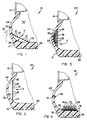
- a first embodiment of a transducer in accordance with the invention is designated generally by reference numeral 10.
- the transducer 10 is associated with a pneumatic tyre 12 which is mounted on a rim 14 to form a wheel for a vehicle (not shown).
- the transducer 10 comprises a passive monitoring means which is essentially formed from a length of copper wire which is coiled to form a coil 11 having a plurality of turns 16.
- the diameter of the turns increases in a direction away from a side wall 24 of the tyre 12 so that the coil is substantially frusto-conical.
- the turns 16 are secured to a flexible membrane 18 which is of a suitable resiliently flexible rubber or plastics material.
- the smaller end 20 of the membrane 18 is secured to the inner surface of the side wall 24 of the tyre 12 and the other, larger end 22 is secured to the inner surface of a tread portion 26 of the tyre 12, so that the membrane stretches between the side wall portion 24 and the tread portion 26 inside the tyre.
- the membrane 18 accordingly defines a chamber 28 together with that portion of the inside surface of the tyre 12 which it spans.
- the ends of the first turn and the last turn are open-circuited. It will be appreciated that the ends of the first turn and the last turn could also be terminated with a discrete impedance component.
- the coil 11 formed by the turns 16 will have a self-inductance and a self-capacitance only and it will oscillate at a particular natural frequency. It will further be appreciated that the selfinductance and the self-capacitance will vary in accordance with the spacing of the turns. Thus, if the membrane 18 flexes, thereby varying the spacing of the turns 16, the natural frequency of oscillation will vary. Thus, as the pressure with in a general chamber 30 defined by the tyre 12 and the rim 14 varies in relation to the pressure in the chamber 28, so the membrane 18 will flex and the resulting natural frequency of oscillation will be representative of the pressure within the wheel.
- the coil 11 formed by the turns 16 may be excited by means of an excitation coil 32 positioned adjacent the wheel in register with the turns 16. Similarly, once the coil 11 has been excited, the frequency of oscillation may be sensed by a similar coil 34 (see Figure 11) which is also positioned adjacent the wheel, but in a diametrically opposed position to the coil 32.
- the coil 32 is supplied with pulses from an amplifier 36 that is connected in turn to a pulse generator 38.
- the amplifier 36 supplies the excitation coil 32 with pulses at a repetition rate that is substantially lower than the natural frequency of oscillation of the coil 11 in the tyre, so that damped oscillations occur in the coil 11.
- the excitation coil 32 and the coil 11 are loosely electrically and magnetically coupled so that the coil 11 is sufficiently excited without perturbing the signal in the coil 32 to any significant extent.
- the sensing coil 34 is connected to a series circuit comprising an amplifier 40, a signal-conditioning circuit 42, a frequency-to-D.C. voltage convertor 44 and a comparator 46.
- the coil 34 senses the oscillations in the coil 11 and provides a signal representative thereof.
- the coil 34 and the coil 11 are also loosely magnetically and electrically coupled so that the sensing coil 34 does not affect the natural frequency of oscillation of the coil 11.
- the signal provided by the sensing coil 34 is amplified by the amplifier 40, conditioned by the circuit 42, and is converted to a D.C.
- FIG. 2 a further embodiment of a transducer 50 is shown therein.
- This transucer 50 is similar to the embodiment 10 shown in Figure 1 and is similarly referenced.
- the turns 16 of the coil 11 are all in the same plane in a spiral manner and the membrane 18 is annular.
- One end of the membrane 18 is secured to the side wall portion 24 close to the rim 14 and the other end 22 is secured to the side wall portion close to the tread portion 26 to define a chamber 52.
- the operation of this system is similar to that of Figure 1 and is not discussed further.
- transducer 60 has four layers, with a first layer of turns secured to the side wall portion 24 and successive turns 16 being secured to three membranes 18.
- a series of chambers 54 are defined and the operation of the system is again similar to the transducers 10 and 50 and will be understood by those skilled in the art without further discussion thereof.
- FIG. 4 a further embodiment of a transducer 70 is shown.
- different turns 16 of the coil are separated by members 72 which are of a suitable dielectric material having a predetermined permittivity.
- the members 72 are connected to a cylindrical base portion 78, the ends of which are flexibly connected to the inner surface of the tread portion 26 by membranes 76 to define a chamber.
- the members 72 are mounted in any suitable resilient manner, for example by spring elements 74 so that the degree to which the members 72 extend between the turns 16 varies in accordance with the pressure within the tyre 12.
- a single turn coil 79 is provided adjacent the side wall portion 24 of the tyre 12 to act as a pick-up.
- the operation of this embodiment 70 is similar to the previous embodiments, it being appreciated that the self-inductance and self-capacitance of the coil formed by the turns 16 will vary in accordance with the extent to which the members 72 extend between the turns 16.
- a further embodiment of a transducer 80 is shown.
- the turns 16 of the coil 11 are secured to raised formations 82 which project inwardly from the inner surface of the side wall portion 24.
- the degree of flexing of the side wall portion 24 will vary, thereby varying the separation of the turns 16 which accordingly affects the self-inductance and self-capacitance to vary the natural frequency of oscillation thereof.
- the transducer 10 comprises a coil 90, the coil 90 being formed from a spiral circular winding 92 of conductive wire. As illustrated in Figure 7, the windings 92 are arranged in layers, with adjacent layers, and adjacent turns of the coil 90 within each layer being separated by corresponding turns of a resilient hollow tube 94 of a non-conductive material such as a synthetic plastics material. Each section of tube 94 separates adjacent turns of the conductors 92.
- the tube 94 and the conductors 12 are encapsulated in a resilient potting compound 96 such as silicone rubber.
- Figures 8 and 9 illustrate various embodiments of the tranducer 10.
- the conductors 92 are wound in three layers, with the turns of adjacent layers being separated by corresponding turns of the tube 94. Adjacent turns in the same layer are separated only by the resilient potting compound 96.
- the conductors 12 are arranged about a central resilient tube 98 which is of a non-conducting material, such as a synthetic plastics material.
- the conductors 92 are held in place about the tube by the potting compound 96.
- the pressure which is applied to the transducer 10 will cause the tubes 94 or 98 to be compressed thereby varying the self-capacitance or self-inductance of the coil 90, and in so doing the frequency of oscillation of the coil 90 will vary.
- the variation of the frequency of oscillation of the coil 90 will be directly proportional to the pressure applied to the coil 90 by the air within the tyre 12.
- a coil having a natural frequency of oscillation of about 1600 kHz may be excited with pulses having a repetition rate of about 160 k-pulses per second in order that suitable damped oscillations are generated in the coil.
Landscapes
- Physics & Mathematics (AREA)
- General Physics & Mathematics (AREA)
- Engineering & Computer Science (AREA)
- Mechanical Engineering (AREA)
- Acoustics & Sound (AREA)
- Health & Medical Sciences (AREA)
- Life Sciences & Earth Sciences (AREA)
- Chemical & Material Sciences (AREA)
- Analytical Chemistry (AREA)
- Biochemistry (AREA)
- General Health & Medical Sciences (AREA)
- Immunology (AREA)
- Pathology (AREA)
- Power Engineering (AREA)
- Measuring Fluid Pressure (AREA)
- Magnetic Resonance Imaging Apparatus (AREA)
- Investigating Or Analyzing Materials By The Use Of Electric Means (AREA)
Claims (21)
- Un système de contrôle passif à commande éléctrique (10, 50, 60, 70, 80) pour un transtraducteur contrôlant la pression d'un pneu, le système de contrôle ayant seulement une résistance ihnérente, une capacitance et une inductance propres, caractérisé en ce que le système de contrôle est disposé de telle façon que la pression contrôlée provoque des variations dans la capacitance et l'inductance propres du système de contrôle, faisant ainsi varier la fréquence propre d'oscillation du système de contrôle, en relation avec les variations de pression.
- Le système de contrôle (10, 50, 60, 80) selon la revendication 1, caractérisé en ce qu'il consiste en une longueur de câble conducteur enroulé en forme de bobine (11, 90) avec des espaces prévus entre les spires adjacentes (16, 92) de la bobine (11, 90).
- Le système de contrôle (10, 50, 60, 80) selon la revendication 2, caractérisé en ce que les spires (16, 92) sont disposées en liaison élastque l'une par rapport à l'autre.
- Le système de contrôle (10, 50, 60, 80) selon la revendication 3, caractérisé en ce qu'une trame flexible élastque (18) est disposée entre les spires (16) de la bobine (11), les dites spires (16) étant fixées sur la trame (18) de telle façon qu'en cours d'utilisation, lorsque la trame (18) fléchit sous l'effet de la pression contrôlée, l'espace entre les spires (16) varie modifiant de ce fait l'inductance et la capacitance propres de la bobine (11) et, par conséquent, sa fréquence propre d'oscillation.
- Le système de contrôle selon la revendication 1, caractérisé en ce que ledit système de contrôle est constitué par, au moins, deux longueurs de conducteurs espacés, disposés en une ligne de transmission bi-câble ou en un câble co-axial.
- Le système de contrôle selon la revendication 5, caractérisé en ce que l'espace entre les conducteurs ou la longueur effective de ceux-ci est variable, pour modifier la fréquence propre d'oscillation du système de contrôle.
- Le système de contrôle (70) selon la revendication 2, caractérisé en ce qu'un élément diélectrique (72, 78) est intercalé entre les spires (16) de la bobine (11), la constante diélectrique de l'élément diélectrique (72, 78) étant variable en réponse aux variations de pression appliquées à ce dispositif pour faire varier la fréquence propre d'oscillation.
- Le système de contrôle selon la revendication 5, caractérisé en ce qu'un élément diélectrique est intercalé entre les longueurs des conducteurs, la constante de l'élément diélectrique étant variable en réponse aux variations de la pression qui lui est appliquée pour faire varier la fréquence propre d'oscillation du système.
- Un transducteur pour contrôler la pression dans un pneu caractérisé en ce qu'il comprend :
- un système de contrôle (10, 50, 60, 70, 80) selon l'une des revendications précédentes ;- un système générant un courant électrique pour fournir de l'énergie au système de contrôle (10, 50, 60, 70, 80) ; et- un capteur pour capter la fréquence propre d'oscillation du système de contrôle (10, 50, 60, 70, 80). - Le transducteur selon la revendication 9, caractérisé en ce que le système générant le courant électrique comporte une bobine (32) de génération de courant électrique qui est couplée électriquement et/ou magnétiquement au système de contrôle (10, 50, 60, 70, 80) par une liaison sans fil pour entretenir le courant dans le système de contrôle (10, 50, 60, 70, 80) et amener ledit système de contrôle à osciller sur sa fréquence propre d'oscillation.
- Le transducteur selon la revendication 10, caractérisé en ce qu'un système générateur d'impulsions (38) est connecté à la bobine de courant électrique (32) pour générer une chaîne d'impulsions à une fréquence suffisamment plus basse que la fréquence propre d'oscillation du système de contrôle (10, 50, 60, 70, 80) de telle façon que des oscillations amorties se produisent dans le système de contrôle (10, 50, 60, 70, 80) en cours d'utilisation.
- Le transducteur selon la revendication 11, caractérisé en ce sens que le capteur comporte une bobine de détection (34) qui est couplée électroniquement et/ou magnétiquement au système de contrôle (10, 50, 60, 70, 80) par un dispositif sans fil.
- Un pneu (12) avec une enveloppe (24, 26), caractérisé en ce qu'un système de contrôle, selon l'une des revendications 1 à 8, est monté à l'intérieur et peut tourner avec ladite enveloppe (24, 26).
- Une méthode de contrôle de pression dans un pneu qui comprend :
- la génération d'un courant électrique dans un système de contrôle passif à commande électrique (10, 50, 60, 70, 80) ayant une résistance inhérente, une capacitance et une inductance propres seulement pour que le système de contrôle (10, 50, 60, 70, 80) oscille à sa fréquence propre d'oscillation ;- la variation de la fréquence propre d'oscillation du dispositif de contrôle (10, 50, 60, 70, 80) en relation avec les variations de pression ; et- le captage des variations de la fréquence propre d'oscillation du dispositif de contrôle (10, 50, 60, 70, 80) pour fournir une indication concernant les variations de pression contrôlées, caractérisée en ce que le fréquence propre d'oscillation du système de contrôle (10, 50, 60, 70, 80) est modifiée en faisant varier la capacitance et l'inductance propres du système de contrôle (10, 50, 60, 70, 80) en relation avec les variations de la pression contrôlée. - La méthode selon la revendication 14, caractérisée en ce que le système de contrôle (10, 50, 60, 70, 80) comprend une longueur de câble conducteur enroulée en forme de bobine (11, 90) comportant une pluralité de spires espacées (16, 92) caractérisée, en outre, en ce que la méthode associe la variation de l'espace entre les spires (16, 92) à la variation de la capacitance et de l'inductance propres de la bobine (11, 90) et, par conséquent, sa fréquence propre d'oscillation en relation avec les variations de la pression qui est appliquée à la bobine (11, 90).
- La méthode selon la revendication 14, caractérisée en ce que le système de contrôle comprend au moins deux longueurs de conducteur qui sont disposées pour former une ligne de transmission bi-câble ou co-axiale caractérisée, en outre, en ce que la méthode consiste, notamment, à faire varier l'espace entre les conducteurs.
- La méthode selon la revendication 14, caractérisée en ce que le système de contrôle (70) comprend une longueur de câble conducteur enroulé en forme de bobine (11) pour fournir une pluralité de spires espacées (16) caractérisée, en outre, en ce que la méthode consiste, notamment, à faire varier la constante diélectrique ou la perméabilité d'un élément (72, 78) intercalé entre les spires (16), ce qui fait varier la fréquence propre d'oscillation de la bobine (11).
- La méthode selon la revendication 17, caractérisée en ce qu'elle comporte la mise en place d'un matériel adéquat entre les spires (16), ledit matériel pouvant se dilater ou se comprimer lors des variations de la pression contrôlée qui est exercée sur le matériel de telle façon que la constante piézo-électrique du dit matériel varie.
- La méthode selon la revendication 18, caractérisée en ce qu'elle comporte l'introduction entre les éléments d'un matériel adéquat (72) approprié à la pression à contrôler de telle façon que la constante piézo-électrique de l'élément (72, 78), entre les spires, varie.
- La méthode selon la revendication 14, caractérisée en ce qu'elle comporte la transmission d'un courant électrique au système de contrôle (10, 50, 60, 70, 80) avec une chaîne d'impulsions.
- La méthode selon la revendication 20, caractérisée en ce qu'elle comporte la transmission d'un courant électrique au système de contrôle (10, 50, 60, 70, 80) avec une chaîne d'impulsions qui a une fréquence suffisamment basse par rapport à la fréquence propre d'oscillation du système de contrôle (10, 50, 60, 70, 80) pour que des oscillations amorties se produisent dans le système de contrôle (10, 50, 60, 70, 80).
Priority Applications (1)
| Application Number | Priority Date | Filing Date | Title |
|---|---|---|---|
| AT87305932T ATE70356T1 (de) | 1986-07-04 | 1987-07-03 | Umsetzer. |
Applications Claiming Priority (4)
| Application Number | Priority Date | Filing Date | Title |
|---|---|---|---|
| ZA864988 | 1986-07-04 | ||
| ZA864988 | 1986-07-04 | ||
| ZA869672 | 1986-12-23 | ||
| ZA869672 | 1986-12-23 |
Publications (2)
| Publication Number | Publication Date |
|---|---|
| EP0254445A1 EP0254445A1 (fr) | 1988-01-27 |
| EP0254445B1 true EP0254445B1 (fr) | 1991-12-11 |
Family
ID=27137217
Family Applications (1)
| Application Number | Title | Priority Date | Filing Date |
|---|---|---|---|
| EP87305932A Expired - Lifetime EP0254445B1 (fr) | 1986-07-04 | 1987-07-03 | Transducteur |
Country Status (5)
| Country | Link |
|---|---|
| US (1) | US4953393A (fr) |
| EP (1) | EP0254445B1 (fr) |
| CA (1) | CA1302730C (fr) |
| DE (1) | DE3775129D1 (fr) |
| ES (1) | ES2028870T3 (fr) |
Families Citing this family (20)
| Publication number | Priority date | Publication date | Assignee | Title |
|---|---|---|---|---|
| US5146203A (en) * | 1990-10-15 | 1992-09-08 | Leonid Simuni | Automobile for racing |
| DE4033053C1 (fr) * | 1990-10-18 | 1992-03-05 | Hottinger Baldwin Messtechnik Gmbh, 6100 Darmstadt, De | |
| GB9107462D0 (en) * | 1991-04-09 | 1991-05-22 | Fluidrive Eng Co Ltd | Measuring temperature |
| SE470561B (sv) * | 1992-12-23 | 1994-08-22 | Ove Linde | Sätt vid övervakning av sträckningsförhållanden vid en fluidbehållare, särskilt en stomipåse jämte en anordning för genomförande av sättet |
| US5541574A (en) * | 1993-12-22 | 1996-07-30 | Palomar Technologies Corporation | Transponder system for communicating with a vehicle tire |
| GB2307044A (en) * | 1995-11-07 | 1997-05-14 | John Michael Jessop | Tyre mileage monitoring apparatus and method |
| US5749984A (en) * | 1995-12-29 | 1998-05-12 | Michelin Recherche Et Technique S.A. | Tire monitoring system and method |
| US5971046A (en) | 1997-09-17 | 1999-10-26 | Bridgestone/Firestone, Inc. | Method and apparatus for bonding an active tag to a patch and a tire |
| US7009506B2 (en) * | 1998-02-10 | 2006-03-07 | Bridgestone Firestone North American Tire, Llc | Electronic monitoring device and patch assembly |
| US6030478A (en) | 1998-02-10 | 2000-02-29 | Bridgestone/Firestone, Inc. | Method and apparatus for removably inserting an electric tire tag into a tire |
| US6244104B1 (en) | 1998-12-04 | 2001-06-12 | Bridgestone/Firestone Research, Inc. | Method for preparing an innerliner of a pneumatic tire for the quick bonding of an electronic monitoring device |
| US6474380B1 (en) | 1999-04-29 | 2002-11-05 | Bridgestone/Firestone North American Tire, Llc | Pneumatic tire and monitoring device including dipole antenna |
| US6970076B1 (en) | 2000-01-14 | 2005-11-29 | Schrader-Bridgeport International, Inc. | Method and apparatus for communication of data in a remote tire monitoring system |
| US8266465B2 (en) | 2000-07-26 | 2012-09-11 | Bridgestone Americas Tire Operation, LLC | System for conserving battery life in a battery operated device |
| US7161476B2 (en) | 2000-07-26 | 2007-01-09 | Bridgestone Firestone North American Tire, Llc | Electronic tire management system |
| JP4231254B2 (ja) * | 2002-08-02 | 2009-02-25 | 横浜ゴム株式会社 | タイヤの歪み状態検出方法、歪み状態検出装置及びそのタイヤ |
| JP4255048B2 (ja) * | 2002-08-02 | 2009-04-15 | 横浜ゴム株式会社 | タイヤの歪み状態検出方法、歪み状態検出装置及びそのセンサユニット並びにこれを備えたタイヤ |
| US7202778B2 (en) * | 2003-08-25 | 2007-04-10 | Rosemount Aerospace Inc. | Wireless tire pressure sensing system |
| CA2511272C (fr) | 2004-06-30 | 2013-12-31 | Socpra Sciences Et Genie S.E.C. | Reseau de capteurs a base d'oscillateurs |
| US9620283B2 (en) | 2014-02-27 | 2017-04-11 | GM Global Technology Operations LLC | Low cost wireless (resistive) sensor based on impedance coupling/modulation using MRC |
Citations (1)
| Publication number | Priority date | Publication date | Assignee | Title |
|---|---|---|---|---|
| DE2262032A1 (de) * | 1972-12-19 | 1974-07-11 | Industrie Automation Gmbh & Co | Mechanisch-elektrischer kraft- oder druckmesswandler |
Family Cites Families (8)
| Publication number | Priority date | Publication date | Assignee | Title |
|---|---|---|---|---|
| US2982127A (en) * | 1957-06-07 | 1961-05-02 | George F Cummings Jr | Strain gage |
| SE410123B (sv) * | 1978-01-31 | 1979-09-24 | Ahlstrom Bengt | Tryckkennande anordning med minst en till en reaktansberoende detekteringskrets, foretredesvis oscillatorkrets, ansluten ledarslinga |
| US4335608A (en) * | 1980-06-23 | 1982-06-22 | Wood Russell J | Submersible pressure transducer device |
| US4409586A (en) * | 1981-05-26 | 1983-10-11 | Hochstein Peter A | Tire condition monitor converter |
| US4389884A (en) * | 1981-06-15 | 1983-06-28 | Gianluigi Agulia | Remote tire pressure indicator |
| DE3205705C2 (de) * | 1982-02-17 | 1986-04-24 | Jakob Dipl.-Ing. 8025 Unterhaching Schillinger | Einrichtung zur Messung einer physikalischen Größe mit einer verformbaren Feder |
| US4578992A (en) * | 1982-11-05 | 1986-04-01 | Philip E. Galasko | Detection of a low pressure condition of a vehicle tire |
| EP0108176A1 (fr) * | 1982-11-05 | 1984-05-16 | Philip Elliot Galasko | Détection d'une condition de sous-pression d'un pneumatique de véhicule |
-
1987
- 1987-07-02 US US07/069,309 patent/US4953393A/en not_active Expired - Fee Related
- 1987-07-03 ES ES198787305932T patent/ES2028870T3/es not_active Expired - Lifetime
- 1987-07-03 EP EP87305932A patent/EP0254445B1/fr not_active Expired - Lifetime
- 1987-07-03 DE DE8787305932T patent/DE3775129D1/de not_active Expired - Lifetime
- 1987-07-03 CA CA000541218A patent/CA1302730C/fr not_active Expired - Lifetime
Patent Citations (1)
| Publication number | Priority date | Publication date | Assignee | Title |
|---|---|---|---|---|
| DE2262032A1 (de) * | 1972-12-19 | 1974-07-11 | Industrie Automation Gmbh & Co | Mechanisch-elektrischer kraft- oder druckmesswandler |
Also Published As
| Publication number | Publication date |
|---|---|
| DE3775129D1 (de) | 1992-01-23 |
| EP0254445A1 (fr) | 1988-01-27 |
| CA1302730C (fr) | 1992-06-09 |
| ES2028870T3 (es) | 1992-07-16 |
| US4953393A (en) | 1990-09-04 |
Similar Documents
| Publication | Publication Date | Title |
|---|---|---|
| US4953393A (en) | Transducer | |
| EP0202375B1 (fr) | Dispositif d'indication de pression de pneu | |
| JP3372503B2 (ja) | タイヤ圧検知システム | |
| US4283780A (en) | Resonant acoustic transducer system for a well drilling string | |
| US3968694A (en) | Gauge for remotely indicating the pressure of a subterranean formation | |
| US4025912A (en) | Method and apparatus for remotely transducing and transmitting pressure and temperature changes | |
| US5790016A (en) | Tire pressure sensing system | |
| US4014015A (en) | Absolute digital position measurement system | |
| US7159774B2 (en) | Magnetic field response measurement acquisition system | |
| US7636052B2 (en) | Apparatus and method for monitoring acoustic energy in a borehole | |
| EP2005221B1 (fr) | Procédé et dispositif servant à détecter une caractéristique de trou de sondage | |
| US4987776A (en) | Level indicator | |
| US6335690B1 (en) | Fluid sensing system | |
| EP0182488A1 (fr) | Mesure à distance de conditions | |
| US4409586A (en) | Tire condition monitor converter | |
| JPH04507289A (ja) | センサ | |
| EP1095800A2 (fr) | Système de mesure de pression d'un pneumatique | |
| JP5934309B2 (ja) | 目的物までの距離を測定するための装置および方法 | |
| US20030102966A1 (en) | Tire pressure sensing system | |
| CA1059233A (fr) | Transducteur acoustique | |
| SE470561B (sv) | Sätt vid övervakning av sträckningsförhållanden vid en fluidbehållare, särskilt en stomipåse jämte en anordning för genomförande av sättet | |
| US4541081A (en) | Electroacoustic transducer | |
| JPH0835893A (ja) | 物理量センサ装置及び当該センサ装置を用いた機器 | |
| US2964730A (en) | Electro-acoustic transducer having coaxially spaced cylindrical coils | |
| WO2001083948A1 (fr) | Sondes de diagraphie prevues pour etre utilisees dans des trous de forage |
Legal Events
| Date | Code | Title | Description |
|---|---|---|---|
| PUAI | Public reference made under article 153(3) epc to a published international application that has entered the european phase |
Free format text: ORIGINAL CODE: 0009012 |
|
| AK | Designated contracting states |
Kind code of ref document: A1 Designated state(s): AT BE CH DE ES FR GB GR IT LI LU NL SE |
|
| 17P | Request for examination filed |
Effective date: 19880718 |
|
| 17Q | First examination report despatched |
Effective date: 19891027 |
|
| GRAA | (expected) grant |
Free format text: ORIGINAL CODE: 0009210 |
|
| AK | Designated contracting states |
Kind code of ref document: B1 Designated state(s): AT BE CH DE ES FR GB GR IT LI LU NL SE |
|
| PG25 | Lapsed in a contracting state [announced via postgrant information from national office to epo] |
Ref country code: SE Effective date: 19911211 Ref country code: NL Effective date: 19911211 Ref country code: GR Free format text: LAPSE BECAUSE OF FAILURE TO SUBMIT A TRANSLATION OF THE DESCRIPTION OR TO PAY THE FEE WITHIN THE PRESCRIBED TIME-LIMIT Effective date: 19911211 Ref country code: BE Effective date: 19911211 Ref country code: AT Effective date: 19911211 |
|
| REF | Corresponds to: |
Ref document number: 70356 Country of ref document: AT Date of ref document: 19911215 Kind code of ref document: T |
|
| REF | Corresponds to: |
Ref document number: 3775129 Country of ref document: DE Date of ref document: 19920123 |
|
| ITF | It: translation for a ep patent filed | ||
| ET | Fr: translation filed | ||
| NLV1 | Nl: lapsed or annulled due to failure to fulfill the requirements of art. 29p and 29m of the patents act | ||
| REG | Reference to a national code |
Ref country code: ES Ref legal event code: FG2A Ref document number: 2028870 Country of ref document: ES Kind code of ref document: T3 |
|
| PG25 | Lapsed in a contracting state [announced via postgrant information from national office to epo] |
Ref country code: LU Free format text: LAPSE BECAUSE OF NON-PAYMENT OF DUE FEES Effective date: 19920731 |
|
| PLBE | No opposition filed within time limit |
Free format text: ORIGINAL CODE: 0009261 |
|
| STAA | Information on the status of an ep patent application or granted ep patent |
Free format text: STATUS: NO OPPOSITION FILED WITHIN TIME LIMIT |
|
| 26N | No opposition filed | ||
| PGFP | Annual fee paid to national office [announced via postgrant information from national office to epo] |
Ref country code: CH Payment date: 19930625 Year of fee payment: 7 |
|
| PGFP | Annual fee paid to national office [announced via postgrant information from national office to epo] |
Ref country code: GB Payment date: 19930705 Year of fee payment: 7 |
|
| PGFP | Annual fee paid to national office [announced via postgrant information from national office to epo] |
Ref country code: ES Payment date: 19930714 Year of fee payment: 7 |
|
| PGFP | Annual fee paid to national office [announced via postgrant information from national office to epo] |
Ref country code: FR Payment date: 19930721 Year of fee payment: 7 |
|
| PGFP | Annual fee paid to national office [announced via postgrant information from national office to epo] |
Ref country code: DE Payment date: 19930831 Year of fee payment: 7 |
|
| PG25 | Lapsed in a contracting state [announced via postgrant information from national office to epo] |
Ref country code: GB Effective date: 19940703 |
|
| PG25 | Lapsed in a contracting state [announced via postgrant information from national office to epo] |
Ref country code: ES Free format text: LAPSE BECAUSE OF EXPIRATION OF PROTECTION Effective date: 19940704 |
|
| PG25 | Lapsed in a contracting state [announced via postgrant information from national office to epo] |
Ref country code: LI Effective date: 19940731 Ref country code: CH Effective date: 19940731 |
|
| GBPC | Gb: european patent ceased through non-payment of renewal fee |
Effective date: 19940703 |
|
| PG25 | Lapsed in a contracting state [announced via postgrant information from national office to epo] |
Ref country code: FR Effective date: 19950331 |
|
| REG | Reference to a national code |
Ref country code: CH Ref legal event code: PL |
|
| PG25 | Lapsed in a contracting state [announced via postgrant information from national office to epo] |
Ref country code: DE Effective date: 19950401 |
|
| REG | Reference to a national code |
Ref country code: FR Ref legal event code: ST |
|
| REG | Reference to a national code |
Ref country code: ES Ref legal event code: FD2A Effective date: 19990601 |
|
| PG25 | Lapsed in a contracting state [announced via postgrant information from national office to epo] |
Ref country code: IT Free format text: LAPSE BECAUSE OF NON-PAYMENT OF DUE FEES;WARNING: LAPSES OF ITALIAN PATENTS WITH EFFECTIVE DATE BEFORE 2007 MAY HAVE OCCURRED AT ANY TIME BEFORE 2007. THE CORRECT EFFECTIVE DATE MAY BE DIFFERENT FROM THE ONE RECORDED. Effective date: 20050703 |