EP0253288A2 - Combined mixing and transporting device for high viscous liquids - Google Patents
Combined mixing and transporting device for high viscous liquids Download PDFInfo
- Publication number
- EP0253288A2 EP0253288A2 EP87109850A EP87109850A EP0253288A2 EP 0253288 A2 EP0253288 A2 EP 0253288A2 EP 87109850 A EP87109850 A EP 87109850A EP 87109850 A EP87109850 A EP 87109850A EP 0253288 A2 EP0253288 A2 EP 0253288A2
- Authority
- EP
- European Patent Office
- Prior art keywords
- housing part
- conveying device
- mixing
- combined mixing
- rotor shaft
- Prior art date
- Legal status (The legal status is an assumption and is not a legal conclusion. Google has not performed a legal analysis and makes no representation as to the accuracy of the status listed.)
- Granted
Links
Images

Classifications
-
- B—PERFORMING OPERATIONS; TRANSPORTING
- B29—WORKING OF PLASTICS; WORKING OF SUBSTANCES IN A PLASTIC STATE IN GENERAL
- B29B—PREPARATION OR PRETREATMENT OF THE MATERIAL TO BE SHAPED; MAKING GRANULES OR PREFORMS; RECOVERY OF PLASTICS OR OTHER CONSTITUENTS OF WASTE MATERIAL CONTAINING PLASTICS
- B29B7/00—Mixing; Kneading
- B29B7/74—Mixing; Kneading using other mixers or combinations of mixers, e.g. of dissimilar mixers ; Plant
- B29B7/7404—Mixing devices specially adapted for foamable substances
- B29B7/7409—Mixing devices specially adapted for foamable substances with supply of gas
- B29B7/7414—Mixing devices specially adapted for foamable substances with supply of gas with rotatable stirrer, e.g. using an intermeshing rotor-stator system
-
- B—PERFORMING OPERATIONS; TRANSPORTING
- B01—PHYSICAL OR CHEMICAL PROCESSES OR APPARATUS IN GENERAL
- B01F—MIXING, e.g. DISSOLVING, EMULSIFYING OR DISPERSING
- B01F33/00—Other mixers; Mixing plants; Combinations of mixers
- B01F33/80—Mixing plants; Combinations of mixers
- B01F33/82—Combinations of dissimilar mixers
- B01F33/822—Combinations of dissimilar mixers with moving and non-moving stirring devices in the same receptacle
-
- B—PERFORMING OPERATIONS; TRANSPORTING
- B01—PHYSICAL OR CHEMICAL PROCESSES OR APPARATUS IN GENERAL
- B01F—MIXING, e.g. DISSOLVING, EMULSIFYING OR DISPERSING
- B01F27/00—Mixers with rotary stirring devices in fixed receptacles; Kneaders
- B01F27/80—Mixers with rotary stirring devices in fixed receptacles; Kneaders with stirrers rotating about a substantially vertical axis
- B01F27/90—Mixers with rotary stirring devices in fixed receptacles; Kneaders with stirrers rotating about a substantially vertical axis with paddles or arms
- B01F27/902—Mixers with rotary stirring devices in fixed receptacles; Kneaders with stirrers rotating about a substantially vertical axis with paddles or arms cooperating with intermeshing elements fixed on the receptacle walls
-
- B—PERFORMING OPERATIONS; TRANSPORTING
- B29—WORKING OF PLASTICS; WORKING OF SUBSTANCES IN A PLASTIC STATE IN GENERAL
- B29B—PREPARATION OR PRETREATMENT OF THE MATERIAL TO BE SHAPED; MAKING GRANULES OR PREFORMS; RECOVERY OF PLASTICS OR OTHER CONSTITUENTS OF WASTE MATERIAL CONTAINING PLASTICS
- B29B7/00—Mixing; Kneading
- B29B7/74—Mixing; Kneading using other mixers or combinations of mixers, e.g. of dissimilar mixers ; Plant
- B29B7/7404—Mixing devices specially adapted for foamable substances
- B29B7/7409—Mixing devices specially adapted for foamable substances with supply of gas
- B29B7/7419—Mixing devices specially adapted for foamable substances with supply of gas with static or injector mixer elements
- B29B7/7423—Mixing devices specially adapted for foamable substances with supply of gas with static or injector mixer elements preceded or followed by rotatable stirring device
Definitions
- the invention relates to a combined mixing and conveying device for highly viscous liquids according to the preamble of claim 1.
- DE-OS 33 13 710 describes a stirring device with which both a mixing and conveying effect can be achieved.
- This mixing and conveying device consists essentially of a cylindrical housing, on the inner wall of which several stationary guide vanes, forming guide wheels, are attached and to which a rotor shaft with impellers runs coaxially, the cylindrical housing with the stationary guide vanes forming on its inner wall
- the stator and the rotor shaft with the impellers arranged thereon form the rotor. It also has a mechanical seal that seals off a mixing chamber from the outside and has lateral inlet openings for the entry of the liquids to be mixed and an outlet opening for the finished mixture.
- the mixing and conveying effect can be increased considerably, especially for work in fiber technology or e.g. in the production of photo emulsions, but the manufacture of the fixed guide vanes forming guide vanes is in the form of complicated shaped spikes for the stator as well the guide wheels for the rotor, which also consist of spikes and are arranged on the rotor shaft, are very complex and correspondingly expensive. Since the characteristics of the stirring device resemble that of a screw conveyor, because of the intensive mixing effect to be achieved, it is still too long and is therefore also expensive to manufacture.
- DE-AS 1 150 360 discloses a kneading and grinding machine for paste-like compositions, in particular for viscous or initially very coarse paste-like compositions such as chocolate compositions, coloring materials and other chemical and pharmaceutical products.
- the kneading and grinding machine has a horizontally arranged double-cylinder trough and two shafts, one of whose cylinder axes is rotatable, revolves at the same speed, and has inclined kneading and grinding elements that reach as far as the cylinder inner surfaces, the spacing of which is smaller than the diameter of the outer edges the circles described in the kneading and grinding organs.
- the kneading and grinding elements of this machine are designed in a manner known per se as circular sector-shaped, preferably flat, arranged in rows and provided with perforations, the wings of one kneading shaft being opposite to those of the other knewing shaft.
- the two shafts are inevitably coupled to one another in such a way that they can be driven in the same direction of rotation and at the same speed and that the rows of wings of the two shafts mesh through one another in the middle of the trough.
- Sector angle and the inclination of the wings and their mutual distance are chosen so that during one revolution of the shafts Cylinder inner surfaces are completely brushed by the outer edges of the wings and that only a small movement distance remains between the side edges of the wings that run past each other when combing through the rows of wings.
- this kneading and grinding machine With this kneading and grinding machine, a particularly strong kneading and rubbing action, e.g. for viscous or initially very coarse paste-like masses, such as chocolate masses, dyes and other chemical and pharmaceutical products, but this kneading and grinding machine is not suitable as a mixing and conveying device for highly viscous liquids. One or more components of the masses in question cannot be mixed in either.
- FR-PS 15 23 920 describes a device for mixing two liquids or gases for producing fuels.
- the components of the liquids or gases are each separately supplied via a line pipe connected by a connection to a housing and arranged perpendicular to this at a higher pressure and a feed pipe which is coaxial to the housing and is flanged to it at a lower pressure End of the mixing process is discharged via an outlet pipe which is also connected by a flange.
- a supply pipe arranged coaxially in the housing and fastened with flanges has a plurality of openings on the periphery, which are connected to an annular chamber created by this pipe.
- a central tube which is attached to this conduit and extends in the longitudinal direction of the housing has a series of openings provided on the circumference, from which the liquid or the gas, after being supplied via a bend and can finally flow into a passage via a hemispherical wall of the inner tube. Because the individual components of the liquids or gases to be mixed can be supplied under different pressures, the movement of the components required for thorough mixing is generated.
- the invention is therefore based on the object of proposing a combined mixing and conveying device for highly viscous liquids, the mixing and conveying device being designed as a single- or multi-stage axial centrifugal pump in which the highly viscous liquids to be mixed can be fed in laterally and during mixing. and conveyors should be arranged so that an upper housing part with essential parts of the device can be lifted off from a lower housing part, so that a changeover from one component to the other is possible without retrofitting and time-consuming cleaning of the device.
- the advantages achieved by the invention consist essentially in the fact that when switching from one component to the other to be mixed and conveyed highly viscous liquids, it is no longer necessary to retrofit devices and their time-consuming cleaning because the combined mixing and conveying device as a single-stage or multi-stage axial centrifugal pump is formed, in which the mixing and delivery elements are arranged in such a way that an upper housing part with essential parts of the device can be easily lifted off the lower housing part after loosening screws. This greatly simplifies the maintenance and cleaning of the mixing and conveying device.
- the individual components are fed in via a lateral connecting piece before they can act on the first impeller.
- the mixing of the relevant, in part highly viscous, liquids is only carried out in the pump itself, a seal fitted in an annular groove preventing the penetration of liquids into the upper housing part, so that the bearing of the rotor shaft cannot be damaged.
- the fact that at least one mixing nozzle is provided in the lateral connection piece allows a second component of a highly viscous liquid to be supplied during the mixing.
- Several holes in the mixing nozzle advantageously ensure better pre-distribution of the second component.
- the impeller blades of the impellers in particular are provided with at least one hole in a known manner.
- Fig. 1 shows a sectional view of an embodiment of the mixing and conveying device according to the invention, which is designed here as a two-stage axial centrifugal pump.
- the axial centrifugal pump is housed in a two-part housing, consisting of a lower housing part 1 and an upper housing part 6.
- the lower housing part 1 has on an inner wall 1i of its cylindrical housing section 1a first and second guide wheels 2a and 2b, which consist of at least two symmetrically arranged guide vanes 2 ⁇ , 2 ⁇ and are arranged opposite one another at the same height.
- a rotor shaft 3 mounted in the upper housing part 6 can be inserted into a mixing chamber 1h of the lower housing part 1.
- At least two inclined impeller blades 4 ⁇ , 4 ⁇ are provided on the rotor shaft 3, each forming first and second impellers 4a and 4b with at least one hole 5.
- the lower housing part 1 has a discharge funnel 1b with an outlet nozzle 1c arranged thereon, which has an outlet opening 1d for the finished mixture and a connection thread 11 on one end side of the lower housing part 1, onto which a union thread (not shown) of a discharge line can be screwed.
- On the right-hand side of the lower housing part 1 there is arranged at right angles to this a connecting piece 1e with a connecting thread 10 for screwing on a union nut of a feed line (not shown) and an inlet opening 1f for a highly viscous liquid.
- the neck 1e has a bore 1g on its underside for inserting a mixing nozzle 12, which has a plurality of outlet holes 13 in its upper part projecting into the neck 1e for better pre-distribution of the second liquid component of the mixture to be mixed.
- a flange 1j On the left side of the lower housing part 1, a flange 1j is provided with a threaded bore 1k, into which a cylinder screw 16 can be screwed for screwing the upper housing part 6 to be described to the lower housing part 1.
- the rotor shaft 3 is supported in ball bearings 7 and 8, which are kept at a distance by a spacer sleeve 7 ⁇ .
- the ball bearing 7 is held in position by a shoulder 3b of the rotor shaft 3 and an annular shoulder 6h in the cylindrical housing section 6a of the upper housing part 6.
- the ball bearing 8, on the other hand, is held firmly in position by a retaining ring 8a which can be inserted into an annular groove 3c of the rotor shaft 3 and by a retaining ring 8b which can be inserted into an annular groove 6i of the upper housing section 1a.
- the Rotor shaft 3 has at one end a cone 3a and at the other end a feather key 9b and a bearing journal 9a with which the rotor shaft 3 can be driven by a motor, not shown.
- the upper housing part 6 has a left flange 6c with a bore 6d, so that the cylinder screw 16 can be inserted therein and the upper housing part 6 can be screwed to the lower housing part 1 by screwing into the threaded bore 1k of the flange 1j.
- a ring shoulder 6f of the upper housing section 6a can be inserted into the lower housing part 1 and at the same time a right flange 6e of the upper housing part 6 also fits the shoulder piece 1e.
- the ring extension 6f has an annular groove 6g on the rotor shaft side for a seal 14 which prevents mixed liquid from the mixing chamber 1h of the axial centrifugal pump from penetrating into the upper housing part 6, where it can possibly damage the bearing of the rotor shaft 3.
- a pressure relief and control opening 15 is provided directly above the right flange 6e of the cylindrical housing section 6a.
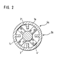
- FIG. 2 shows a cross-sectional view through a lower housing section 1a of the mixing and conveying device according to the invention.
- Opposing guide vanes 2 ⁇ of the first guide wheel 2a are arranged on the inner wall 1i of the housing section 1a.
- the rotor shaft 3 carries four opposing, inclined impeller blades 4 ⁇ , each with two holes. All the impellers 4a, 4b provided on the rotor shaft 3 and all on the inner wall 1i of the housing Section 1a attached guide wheels 2a, 2b are arranged so that the housing part 6 together with the rotor shaft 3 with their bearings 7, 8 and the impellers 4a, 4b can be lifted axially after loosening cylinder screws, not shown here, so that the maintenance and cleaning of the mixing and conveyor is very simplified.
Landscapes
- Chemical & Material Sciences (AREA)
- Chemical Kinetics & Catalysis (AREA)
- Engineering & Computer Science (AREA)
- Mechanical Engineering (AREA)
- Accessories For Mixers (AREA)
- Structures Of Non-Positive Displacement Pumps (AREA)
- Mixers Of The Rotary Stirring Type (AREA)
- Processing And Handling Of Plastics And Other Materials For Molding In General (AREA)
- Feeding, Discharge, Calcimining, Fusing, And Gas-Generation Devices (AREA)
Abstract
Description
Die Erfindung betrifft eine kombinierte Misch-und Fördereinrichtung für hochviskose Flüssigkeiten gemäß dem Oberbegriff des Anspruchs 1.The invention relates to a combined mixing and conveying device for highly viscous liquids according to the preamble of
Wenn es auf sehr homogene Gemische hochviskoser Flüssigkeiten aus zwei oder mehreren Komponenten ankommt, wobei zumindest eine dieser Komponenten hochviskos ist, wird normalerweise in getrennten Einruchtungen gemischt und gefördert. Ein besonderer Nachteil dieser Einrichtungen besteht dann darin, daß bei Umstellung von der einen auf die andere Komponente beide Einrichtungen umgerüstet und zeitraubend gesäubert werden müssen, was bei der Verarbeitung hockviskoser Flüssigkeiten, speziell in der Kunststoffindustrie, zu einem hohen Arbeitsaufwand führt.When it comes to very homogeneous mixtures of highly viscous liquids consisting of two or more components, at least one of these components being highly viscous, mixing and conveying are usually carried out in separate devices. A particular disadvantage of these devices is that when switching from one component to the other, both devices have to be converted and time-consuming cleaned, which leads to a high workload when processing high-viscosity liquids, especially in the plastics industry.
Kombinierte Misch- und Fördereinrichtungen für hochviskose Flüssigkeiten der eingangs genannten Art sind bereits bekannt. So ist in der DE-OS 33 13 710 eine Rührvorrichtung beschrieben, mit der sowohl eine Misch-als auch Förderwirkung erzielt werden kann. Diese Misch- und Fördereinrichtung besteht im wesentlichen aus einem zylindrischen Gehäuse, an dessen Innenwand mehrere feststehende Leitschaufeln, Leiträder bildent, angebracht sind und zu dem koaxial eine Läuferwelle mit Laufrädern verläuft, wobei das zylindrische Gehäuse mit den an seiner Innenwand feststehenden, Leiträder bildenden Leitschaufeln den Stator und die Läuferwelle mit den daran angeordneten Laufrädern den Rotor bilden. Sie weist ferner eine Gleitringdichtung auf, die einen Mischraum nach außen hin abdichtet und hat seitliche Eintrittsöffnungen zum Eintreten der zu mischenden Flüssigkeiten und eine Austrittsöffnung für die fertige Mischung.Combined mixing and conveying devices for highly viscous liquids of the type mentioned are already known. DE-OS 33 13 710 describes a stirring device with which both a mixing and conveying effect can be achieved. This mixing and conveying device consists essentially of a cylindrical housing, on the inner wall of which several stationary guide vanes, forming guide wheels, are attached and to which a rotor shaft with impellers runs coaxially, the cylindrical housing with the stationary guide vanes forming on its inner wall The stator and the rotor shaft with the impellers arranged thereon form the rotor. It also has a mechanical seal that seals off a mixing chamber from the outside and has lateral inlet openings for the entry of the liquids to be mixed and an outlet opening for the finished mixture.
Mit dieser Rührvorrichtung kann zwar die Misch- und Förderwirkung, insbesondere für Arbeiten in der Fasertechnik oder z.B. bei der Herstellung von Fotoemulsionen beträchtlich erhöht werden, doch ist die Fertigung der feststehenden, Leiträder bildenden Leitschaufeln in Form von kompliziert geformten Stacheln für den Stator wie auch die der ebenfalls aus Stacheln bestehenden, an der Läuferwelle angeordneten Leiträder für den Rotor sehr aufwendig und entsprechend teuer. Da die Rührvorrichtung in ihrer Charakteristik einer Förderschnecke ähnelt, hat sie wegen der zu erzielenden intensiven Mischwirkung auch eine noch zu lange Baulänge und ist daher ebenfalls teuer in der Herstellung. Auch ist, wenn in getrennten Rührvorrichtungen gemischt und gefördert wird, für die Umstellung von der einen auf die andere Komponente eine Umrüstung und zeitraubende Säuberung dieser Vorrichtungen notwendig, was bei der Verarbeitung hochviskoser Flüssigkeiten, speziell in der Kunststoffindustrie, zu einem hohen Arbeitsaufwand führt. Eine Zumischung einer oder mehrerer Komponenten während des Mischens oder Förderns ist ebenfalls nicht möglich.With this stirring device, the mixing and conveying effect can be increased considerably, especially for work in fiber technology or e.g. in the production of photo emulsions, but the manufacture of the fixed guide vanes forming guide vanes is in the form of complicated shaped spikes for the stator as well the guide wheels for the rotor, which also consist of spikes and are arranged on the rotor shaft, are very complex and correspondingly expensive. Since the characteristics of the stirring device resemble that of a screw conveyor, because of the intensive mixing effect to be achieved, it is still too long and is therefore also expensive to manufacture. Also, when mixing and conveying in separate stirring devices, one is for the changeover from one component to the other Retrofitting and time-consuming cleaning of these devices is necessary, which leads to a high workload when processing highly viscous liquids, especially in the plastics industry. It is also not possible to add one or more components during mixing or conveying.
Aus der DE-AS 1 150 360 ist eine Knet- und Verreibungsmaschine für pastenartige Massen, insbesondere für zähe oder angänglich sehr grobstückige pastenartige Massen, wie Schokoladenmassen, Farbgrundstoffe sowie andere chemische und pharmazeutische Erzeugnisse, bekannt. Die Knet- und Verreibungsmaschine hat einen liegend angeordneten Doppelzylindertrog und zwei ein dessen Zylinderachsen drehbar gelagerten, mit gleicher Drehzahl umlaufenden sowie mit schräg stehenden und bis an die Zylinderinnenflächen heranreichenden Knet- und Verreibungsorganen versehenen Wellen, deren Abstand kleiner ist als der Durchmesser der von den Außenkanten der Knet- und Verreibungsorgane beschriebenen Kreise. Die Knet- und Verreibungsorgane dieser Maschine sind in an sich bekannter Weise als kreissektorförmige, vorzugsweise ebene, in Reihen angeordnete und mit Durchbrechungen versehene Flügel ausgebildet, wobei die Flügel der einen Knetwelle zu denen der anderen Knewtwelle entgegengesetzt schräg gestellt sind.DE-AS 1 150 360 discloses a kneading and grinding machine for paste-like compositions, in particular for viscous or initially very coarse paste-like compositions such as chocolate compositions, coloring materials and other chemical and pharmaceutical products. The kneading and grinding machine has a horizontally arranged double-cylinder trough and two shafts, one of whose cylinder axes is rotatable, revolves at the same speed, and has inclined kneading and grinding elements that reach as far as the cylinder inner surfaces, the spacing of which is smaller than the diameter of the outer edges the circles described in the kneading and grinding organs. The kneading and grinding elements of this machine are designed in a manner known per se as circular sector-shaped, preferably flat, arranged in rows and provided with perforations, the wings of one kneading shaft being opposite to those of the other knewing shaft.
Die beiden Wellen sind derart zwangsläufig miteinander gekuppelt, daß sie im gleichen Drehsinn und mit gleicher Geschwindigkeit antreibbar sind und daß die Flügelreihen der beiden Wellen in der Trogmitte durcheinander hindurchkämmen. Sektorwinkel und die Schrägstellung der Flügel sowie ihr gegenseitiger Abstand sind so gewählt, daß während einer Umdrehung der Wellen die Zylinderinnenflächen vollständig von den Außenkanten der Flügel bestrichen werden und daß zwischen den beim Hindurchkämmen der Flügelreihen aneinander vorbeilaufenden Seitenkanten der Flügel nur ein geringer Bewegungsabstand verbleibt.The two shafts are inevitably coupled to one another in such a way that they can be driven in the same direction of rotation and at the same speed and that the rows of wings of the two shafts mesh through one another in the middle of the trough. Sector angle and the inclination of the wings and their mutual distance are chosen so that during one revolution of the shafts Cylinder inner surfaces are completely brushed by the outer edges of the wings and that only a small movement distance remains between the side edges of the wings that run past each other when combing through the rows of wings.
Mit dieser Knet- und Verreibungsmaschine kann zwar eine besonders starke Knet- und Reibwirkung, z.B. für zähe oder anfänglich sehr grobstückige pastenartige Massen, wie Schokoladenmassen, Farbstoffe sowie andere chemische und pharmazeutische Erzeugnisse erzielt werden, doch ist diese Knet- und Verreibungsmaschine nicht als Misch- und Fördereinrichtung für hochviskose Flüssigkeiten geeignet. Eine oder mehrere Komponenten der infrage stehenden Massen können auch nicht zusätzlich zugemischt werden.With this kneading and grinding machine, a particularly strong kneading and rubbing action, e.g. for viscous or initially very coarse paste-like masses, such as chocolate masses, dyes and other chemical and pharmaceutical products, but this kneading and grinding machine is not suitable as a mixing and conveying device for highly viscous liquids. One or more components of the masses in question cannot be mixed in either.
In der FR-PS 15 23 920 ist eine Einruchtung zum Mischen zweier Flüssigkeiten oder Gase zur Hertellung von Brennstoffen beschrieben. Die Komponenten der Flüssigkeiten bzw. Gase werden jeweils getrennt über ein durch einen Anschluß mit einem Gehäuse verbundenen und senkrecht zu diesem angeordneten Leitungsrohr bei höherem Druck und ein Zuführungsrohr, das koaxial zum Gehäuse liegt und an diesem angeflanscht ist, bei schwächerem Druck zugeführt bzw. nach Beenden des Mischvorganges über ein ebenfalls durch einen Flansch verbundenes Ausgangsrohr abgeführt. Ein koxial im Gehäuse angeordnetes und mit Flanschen befestigtes Zuleitungsrohr weist am Umfang mehrere Öffnungnen auf, die mit einer durch dieses Leitungsrohr geschaffenen Ringkammer in Verbindung stehen. Ein an diesem Leitungsrohr angebrachtes zentrales und sich in Längsrichtung des Gehäuses erstreckendes Innenrohr hat eine Reihe von am Umfang vorgesehenen Öffnung, aus denen die Flüssigkeit bzw. das Gas nach Zuführen über einen Krümmer und schließlich über eine Halbkugelwand des Innenrohres in einen Durchgang einfließen bzw. einströmen kann. Dadurch, daß die einzelnen Lomponenten der zu mischenden Flüssigkeiten bzw. der Gase unter unterschiedlichen Drucken zuführbar sind, wird die erforderliche Bewegung der Kompenenten für ihre gründliche Durchmischung erzeugt.FR-
Aus der Beschreibung dieser Einrichtung geht somit deutlich hervor, daß sie zwar zur Herstellung homogener Mischungen aus zwei Flüssigkeiten oder Gasen durchaus geeignet ist, daß sie aber zum kombinierten Mischen und Fördern hochviskoser Flüssigkeiten wegen ihres Aufbaues überhaupt nicht verwendbar ist. Bei dem senkrecht zum Gehäuse angebrachten Zuleitungsrohr handelt es sich auch nicht um eine Mischdüse.From the description of this device it is clear that it is indeed suitable for producing homogeneous mixtures of two liquids or gases, but because of its structure it cannot be used for the combined mixing and conveying of highly viscous liquids. The supply pipe attached perpendicular to the housing is also not a mixing nozzle.
Der Erfindung liegt daher die Aufgabe zugrunde, eine kombinierte Misch- und Fördereinrichtung für hochviskose Flüssigkeiten vorzuschlagen, wobei die Misch- und Fördereinrichtung als ein- oder mehrstufige Axialkreiselpumpe ausgebildet sein soll, bei der die zu mischenden hochviskosen Flüssigkeiten seitlich zuführbar sind und bei der Misch- und Förderorgane so angeordnet sein sollen, daß ein oberes Gehäuseteil mit wesentlichen Teilen der Einrichtung von einem unteren Gehäuseteil abhebbar ist, so daß eine Umstellung von der einen auf die andere Komponente ohne Umrüstung und aufwendige Säuberung der Einrichtung möglich ist.The invention is therefore based on the object of proposing a combined mixing and conveying device for highly viscous liquids, the mixing and conveying device being designed as a single- or multi-stage axial centrifugal pump in which the highly viscous liquids to be mixed can be fed in laterally and during mixing. and conveyors should be arranged so that an upper housing part with essential parts of the device can be lifted off from a lower housing part, so that a changeover from one component to the other is possible without retrofitting and time-consuming cleaning of the device.
Diese Aufgabe wird mit den Merkmalen des kennzeichnenden Teils von Anspruch 1 gelöst.This object is achieved with the features of the characterizing part of
Weitere Ausgestaltungen der Erfindung ergeben sich aus den Unteransprüchen 2 bis 12.Further refinements of the invention result from
Die mit der Erfindung erzielten Vorteile bestehen im wesentlichen darin, daß bei der Umstellung von der einen auf die andere Komponente von zu mischenden und fördernden hochviskosen Flüssigkeiten ein Umrüsten von Einrichtungen und ihr zeitraubended Reinigen nicht mehr erforderlich sind, weil die kombinierte Misch- und Fördereinrichtung als eine ein- oder mehrstufige Axialkreiselpumpe ausgebildet ist, bei der Misch- und Förderorgane so angeordnet sind, daß ein oberes Gehäuseteil mit wesentlichen Teilen der Einruchtung nach Lösen von Schrauben vom unteren Gehäusteil leicht abhebbar ist. Hierdurch wird die Wartung und Reinigung der Misch- und Fördereinrichtung sehr vereinfacht. Die einzelnen Komponenten werden erfindungsgemäß über einen seitlichen Ansatzstutzen zugeführt, bevor sie das erste Laufrad beaufschlagen können. Das Mischen der betreffenden, zum Teil hochviskosen Flüssigkeiten wird nur in der Pumpe selbst vorgenommen, wobei eine in einer Ringnut angebrachte Dichtung das Eindringen von Flüssigkeiten in das obere Gehäuseteil verhindert, so daß die Lagerung der Läuferwelle nicht beschädigt werden kann. Dadurch, daß mindestens eine Mischdüse im seitlichen Ansatzstutzen vorgesehen ist, kann eine zweite Komponente einer hochviskosen Flüssigkeit während des Mischens zugeführt werden. Mehrere Löcher in der Mischdüse sorgen in vorteilhafter Weise für eine bessere Vorverteilung der zweiten Komponente. Zur besseren Verwirbelung der Mischung in der Axialkreiselpumpe sind insbesondere die Laufradschaufeln der Laufräder in bekannter Weise mit mindestens einem Loch versehen.The advantages achieved by the invention consist essentially in the fact that when switching from one component to the other to be mixed and conveyed highly viscous liquids, it is no longer necessary to retrofit devices and their time-consuming cleaning because the combined mixing and conveying device as a single-stage or multi-stage axial centrifugal pump is formed, in which the mixing and delivery elements are arranged in such a way that an upper housing part with essential parts of the device can be easily lifted off the lower housing part after loosening screws. This greatly simplifies the maintenance and cleaning of the mixing and conveying device. According to the invention, the individual components are fed in via a lateral connecting piece before they can act on the first impeller. The mixing of the relevant, in part highly viscous, liquids is only carried out in the pump itself, a seal fitted in an annular groove preventing the penetration of liquids into the upper housing part, so that the bearing of the rotor shaft cannot be damaged. The fact that at least one mixing nozzle is provided in the lateral connection piece allows a second component of a highly viscous liquid to be supplied during the mixing. Several holes in the mixing nozzle advantageously ensure better pre-distribution of the second component. To improve the swirling of the mixture in the axial centrifugal pump, the impeller blades of the impellers in particular are provided with at least one hole in a known manner.
Ausführungsbeispiele der Erfindung sind in der Zeichnung dargestellt und werden im folgenden näher beschrieben. Es zeigen
- Fig. 1 eine Schnittansicht der erfindungsgemäßen Misch- und Fördereinrichtung und
- Fig. 2 eine Querschnittsansicht durch das untere Gehäuseteil der erfindungsgemäßen Misch- und Fördereinrichtung.
- Fig. 1 is a sectional view of the mixing and conveying device according to the invention and
- Fig. 2 is a cross-sectional view through the lower housing part of the mixing and conveying device according to the invention.
Fig. 1 zeigt in einer Schnittansicht eine Ausführungsform der erfindungsgemäßen Misch- und Fördereinrichtung, die hier als zweistufige Axialkreiselpumpe ausgebildet ist. Bei geringeren Ansprüchen an die Qualität der zu mischenden Flüssigkeiten genügt jedoch nur eine Stufe, während bei besonders hohen Qualitätsanforderungen mehr als zwei Stufen benutzt werden müssen. Die Axialkreiselpumpe ist in einem zweiteiligen Gehäuse, bestehend aus einem unteren Gehäusteil 1 und einem oberen Gehäuseteil 6, untergebracht. Das untere Gehäuseteil 1 weist an einer Innenwand 1i ihres zylindrischen Gehäuseabschnitts 1a erste und zweite Leiträder 2a und 2b auf, die aus mindestens zwei symmetrisch zueinander angeordneten Leitschaufeln 2ʹ, 2ʺ bestehen und in gleicher Höhe einander gegenüberliegend angeordnet sind. Sie können zwecks besserer Verwirbelung einer hochviskosen Flüssigkeit bzw. Mischung mit mindestens einem Loch versehen sein. In einen Mischraum 1h des unteren Gehäuseteils 1 ist eine im oberen Gehäuseteil 6 gelagerte Läuferwelle 3 einsetzbar. An der Läuferwelle 3 sind mindestens zwei schräg gestellte Laufradschaufeln 4ʹ, 4ʺ vorgesehen, die jeweils erste und zweite Laufräder 4a und 4b mit mindestens einem Loch 5 bilden.Fig. 1 shows a sectional view of an embodiment of the mixing and conveying device according to the invention, which is designed here as a two-stage axial centrifugal pump. With lower demands on the quality of the liquids to be mixed, however, only one step is sufficient, while with particularly high quality requirements more than two steps have to be used. The axial centrifugal pump is housed in a two-part housing, consisting of a
Das untere Gehäuseteil 1 weist einen Abflußtrichter 1b mit einem daran angeordneten Abzugstutzen 1c auf, der an einer Endseite des unteren Gehäuseteils 1 eine Austrittsöffnung 1d für die fertige Mischung und ein Anschlußgewinde 11 hat, auf das ein nicht dargestelltes Überwurfgewinde einer Abführleitung aufschraubbar ist. Auf der rechten Seite des unteren Gehäuseteils 1 ist rechtwinklig dazu ein Ansatzstutzen 1e mit einem Anschlußgewinde 10 zum Aufschrauben einer Überwurfmutter einer nicht gezeigten Zufuhrleitung und eine Eintrittsöffnung 1f für eine hochviskose Flüssigkeit angeordnet. Der Ansatzstutzen 1e hat an einer Unterseite eine Bohrung 1g zum Einsetzen einer Mischdüse 12, die in ihrem, in den Ansatzstutzen 1e hineinragenden oberen Teil mehrere Austrittslöcher 13 für eine bessere Vorverteilung der zuzumischenden zweiten flüssigen Komponente der Mischung aufweist.The
Auf der linken Seite des unteren Gehäuseteils 1 ist ein Flansch 1j mit einer Gewindebohrung 1k vorgesehen, in die eine Zylinderschraube 16 zum Verschrauben des noch zu beschreibenden oberen Gehäuseteils 6 mit dem unteren Gehäusteil 1 einschraubbar ist.On the left side of the
Im oberen zylindrischen Gehäuseteil 6 ist die Läuferwelle 3 in Kugellagern 7 und 8 gelagert, die durch eine Distanzhülse 7ʹ auf Abstand gehalten sind. Das Kugellager 7 ist dabei durch einen Absatz 3b der Läuferwelle 3 und einen Ringansatz 6h im zylindrischen Gehäuseabschnitt 6a des oberen Gehäuseteils 6 in Position gehalten. Das Kugellager 8 wird hingegen durch einen in eine Ringnut 3c der Läuferwelle 3 einsetzbaren Haltering 8a sowie durch einen in eine Ringnut 6i des oberen Gehäuseabschnittes 1a einsetzbaren Haltering 8b fest in Position gehalten. Die Läuferwelle 3 hat an dem einen Ende einen Konus 3a und am anderen Ende eine Paßfeder 9b sowie einen Lagerzapfen 9a, mit dem die Läuferwelle 3 von einem nicht gezeigten Motor antreibbar ist.In the upper
Das obere Gehäusteil 6 weist einen linken Flansch 6c mit einer Bohrung 6d auf, so daß die Zylinderschraube 16 in diese einsetzbar und durch Einschrauben in die Gewindebohrung 1k des Flansches 1j das obere Gehäuseteil 6 mit dem unteren Gehäuseteil 1 verschraubbar ist. Hierbei ist ein Ringansatz 6f des oberen Gehäuseabschnittes 6a in das untere Gehäuseteil 1 passend einsetzbar und wobei zugleich ein rechter Flansch 6e des oberen Gehäuseteils 6 dem Ansatzstutzen 1e ebenfalls passend anliegt.The
Der Ringansatz 6f weist läuferwellenseitig eine Ringnut 6g für eine Dichtung 14 auf, die verhindert, daß Mischflüssigkeit aus dem Mischraum 1h der Axialkreiselpumpe in das obere Gehäuseteil 6 eindringt, wo sie möglicherwise die Lagerung der Läuferwelle 3 beschädigen kann. Unmittelbar über dem rechten Flansch 6e des zylindrischen Gehäuseabschnittes 6a ist eine Druckentlastungs- und Kontrollöffnung 15 vorgesehen.The
Fig. 2 zeigt eine Querschnittsansicht durch einen unteren Gehäuseabschnitt 1a der erfindungsgemäßen Misch- und Fördereinrichtung. An der Innenwand 1i des Gehäuseabschnittes 1a sind einander gegenüberstehende Leitschaufeln 2ʹ des ersten Leitrades 2a angeordnet. Die Läuferwelle 3 trägt vier einander gegenüberstehende, schräg gestellte Laufradschaufeln 4ʹ mit jeweils zwei Löchern. Alle an der Läuferwelle 3 vorgesehenen Laufräder 4a, 4b und alle an der Innenwand 1i des Gehäuse abschnitts 1a angebrachten Leiträder 2a, 2b sind so angeordnet, daß das Gehäuseteil 6 samt Läuferwelle 3 mit deren Lagerung 7, 8 und den Laufrädern 4a, 4b nach Lösen von hier nicht gezeigten Zylinderschrauben axial heraushebbar ist, so daß die Wartung und Reiningung der Misch- und Fördereinrichtung sehr vereinfacht ist.2 shows a cross-sectional view through a
Als besonders vorteilhaft hat es sich herausgestellt, wenn die in den Ansatzstutzen 1e eingesetzte Mischdüse 12 um ihre Achse rotierend ausgebildet ist. Hierdurch wird eine noch effektivere Mischung erhalten.It has turned out to be particularly advantageous if the mixing
Claims (13)
Priority Applications (1)
| Application Number | Priority Date | Filing Date | Title |
|---|---|---|---|
| AT87109850T ATE69995T1 (en) | 1986-07-16 | 1987-07-08 | COMBINED MIXING AND CONVEYING DEVICE FOR HIGH VISCOSE LIQUIDS. |
Applications Claiming Priority (2)
| Application Number | Priority Date | Filing Date | Title |
|---|---|---|---|
| DE3623932 | 1986-07-16 | ||
| DE3623932A DE3623932A1 (en) | 1986-07-16 | 1986-07-16 | COMBINED MIXING AND CONVEYING DEVICE FOR HIGH VISCOSE LIQUIDS |
Publications (3)
| Publication Number | Publication Date |
|---|---|
| EP0253288A2 true EP0253288A2 (en) | 1988-01-20 |
| EP0253288A3 EP0253288A3 (en) | 1989-11-29 |
| EP0253288B1 EP0253288B1 (en) | 1991-12-04 |
Family
ID=6305255
Family Applications (1)
| Application Number | Title | Priority Date | Filing Date |
|---|---|---|---|
| EP87109850A Expired - Lifetime EP0253288B1 (en) | 1986-07-16 | 1987-07-08 | Combined mixing and transporting device for high viscous liquids |
Country Status (4)
| Country | Link |
|---|---|
| US (1) | US4805154A (en) |
| EP (1) | EP0253288B1 (en) |
| AT (1) | ATE69995T1 (en) |
| DE (2) | DE3623932A1 (en) |
Cited By (6)
| Publication number | Priority date | Publication date | Assignee | Title |
|---|---|---|---|---|
| EP0394007A2 (en) * | 1989-04-18 | 1990-10-24 | Halliburton Company | Mixing apparatus for fluids |
| FR2680983A1 (en) * | 1991-09-10 | 1993-03-12 | Inst Francais Du Petrole | CONTINUOUS MIXER DEVICE, METHOD AND USE IN A PUMPING PLANT OF A HIGH VISCOSITY FLUID. |
| EP0614812A1 (en) * | 1993-03-12 | 1994-09-14 | Dow Corning Corporation | Nozzle mixer assembly |
| CN102059067A (en) * | 2011-01-17 | 2011-05-18 | 西安华晶电子技术有限公司 | Multi-shaft mortar and high-viscosity fluid stirrer for axial turbulent flow pattern multi-wire cutting machine |
| CN101693171B (en) * | 2009-10-22 | 2012-04-18 | 天津大学 | High speed dynamic state on-line mixing device applicable to large-scale mixing |
| WO2016019213A1 (en) * | 2014-07-31 | 2016-02-04 | Dow Global Technologies Llc | In-line dynamic mixing apparatus for flocculating and dewatering oil sands fine tailings |
Families Citing this family (19)
| Publication number | Priority date | Publication date | Assignee | Title |
|---|---|---|---|---|
| JPH0710337B2 (en) * | 1988-07-04 | 1995-02-08 | 三洋化成工業株式会社 | Stirrer |
| US4934828A (en) * | 1989-06-07 | 1990-06-19 | Ciba-Geigy Corporation | Apparatus for mixing viscous materials |
| DE4028108C1 (en) * | 1990-09-05 | 1992-05-27 | Imcatec-Gmbh Maschinen Fuer Die Verfahrenstechnik, 6800 Mannheim, De | |
| DE4140731C2 (en) * | 1991-12-11 | 2003-12-24 | Teves Gmbh Alfred | Washing system, in particular for windows of a motor vehicle |
| US5304355A (en) * | 1992-09-08 | 1994-04-19 | Quantum Technologies Inc. | Mixer-reactor equipment for treating fine solids with gaseous reagents |
| DE9318098U1 (en) * | 1993-11-26 | 1994-03-17 | Schneider Friedhelm | Mixing device for highly viscous liquids |
| DE19812407A1 (en) * | 1998-03-20 | 1999-09-23 | Michael Marmetschke | Water-oil emulsion-based impregnant production containing additive e.g. pigment or gelling agent, useful for wood treatment |
| US20050040386A1 (en) * | 2001-02-20 | 2005-02-24 | Fow-Sen Choa | Multiple quantum well broad spectrum gain medium and method for forming same |
| DE10141459C2 (en) * | 2001-08-23 | 2003-08-07 | Polymaterials Ag | Method and device for the production and testing of moldings |
| FR2840546B1 (en) * | 2002-06-07 | 2005-02-25 | Atofina | METHOD FOR MIXING CONTENT DYNAMICALLY AT LEAST TWO FLUIDS AND MICROMELANGER |
| DE10242100A1 (en) * | 2002-09-11 | 2004-03-25 | Hennecke Gmbh | Continuous mixing of polyol and isocyanate to produce reactive polyurethane mixture involves use of an impeller mixer with a specified number of angled blades in planes along the shaft |
| US20080037361A1 (en) * | 2006-02-15 | 2008-02-14 | Jerry Fleishman | Mixer apparatus |
| ATE467453T1 (en) * | 2006-09-12 | 2010-05-15 | Voss Chemie | DEVICE SYSTEM FOR PRODUCING A READY-TO-USE FILLING COMPOUND BY MIXING A BINDER AND A HARDENER COMPONENT |
| DE202007016136U1 (en) * | 2007-05-31 | 2008-03-27 | Vosschemie Gmbh | Device for producing a ready-to-use filler by mixing a binder and a hardener component |
| US20080267005A1 (en) * | 2007-04-24 | 2008-10-30 | Tyco Healthcare Group Lp | Applicator system and method of use |
| US8672029B2 (en) * | 2009-12-30 | 2014-03-18 | Schlumberger Technology Corporation | System for reducing foam in mixing operations |
| GB2511476A (en) * | 2012-12-07 | 2014-09-10 | Thomas Andreas Guenther | Device and system for hydrocarbon conversion |
| CN106040065A (en) * | 2016-05-26 | 2016-10-26 | 广西梧州龙鱼漆业有限公司 | Paint pre-dispersing device |
| DE102019103945B4 (en) | 2019-02-15 | 2022-04-28 | Hennecke Gmbh | Process for the continuous mixing of at least one polyol component with at least one isocyanate component and stirrer mixer |
Citations (10)
| Publication number | Priority date | Publication date | Assignee | Title |
|---|---|---|---|---|
| DE575198C (en) * | 1931-08-25 | 1933-04-26 | Steckborn Kunstseide Akt Ges | Device for producing emulsions |
| GB856708A (en) * | 1958-10-09 | 1960-12-21 | Union Carbide Corp | Method and apparatus for mixing materials forming viscous masses |
| US2991503A (en) * | 1958-01-06 | 1961-07-11 | Rietz Mfg Co | Breaking, mixing, and extrusion apparatus |
| DE1155234B (en) * | 1958-02-06 | 1963-10-03 | Dunlop Rubber Co | Method and device for producing polyurethane foams |
| US3207486A (en) * | 1963-02-21 | 1965-09-21 | Gabriel Williams Co Inc | Mixing apparatus for quickly reactive components |
| GB1071082A (en) * | 1962-10-25 | 1967-06-07 | Perameters Company Ltd | Improvements in or relating to the manufacture of moulded polyurethane foams |
| FR2183570A1 (en) * | 1972-05-10 | 1973-12-21 | Serre | Foam polymn and dispensing head - incorporating several rotary impellers for homogenising or expulsion of mixt |
| US3873072A (en) * | 1971-08-02 | 1975-03-25 | Monsanto Co | Melt extrusion |
| US3920225A (en) * | 1974-10-01 | 1975-11-18 | Raymond Lee Organization Inc | Centrifugal chemical mixer |
| US3938783A (en) * | 1970-10-30 | 1976-02-17 | The Upjohn Company | Method for continuous mixing of foam materials |
Family Cites Families (8)
| Publication number | Priority date | Publication date | Assignee | Title |
|---|---|---|---|---|
| US214729A (en) * | 1879-04-22 | Improvement in combined churn and ice-cream freezer | ||
| DE1150360B (en) * | 1960-05-09 | 1963-06-20 | Richard Frisse Maschinenfabrik | Kneading and triturating machine for pasty masses |
| FR1523920A (en) * | 1967-05-24 | 1968-05-03 | Zink Co John | Device for mixing fluids |
| CH460718A (en) * | 1967-06-22 | 1968-08-15 | Buss Ag | Additional device on a mixing and kneading device for the further treatment of soft pasty products |
| GB1390190A (en) * | 1971-07-01 | 1975-04-09 | Wisz E | Mixing apparatus and method |
| DE2852499A1 (en) * | 1978-12-05 | 1980-06-19 | Schwing Gmbh F | MIXERS FOR DICKERS, e.g. FOR FILTER CAKE, SLUDGE OR THE LIKE |
| US4334788A (en) * | 1980-07-15 | 1982-06-15 | Miner Robert M | Pin action mixing pump |
| DE3313710A1 (en) * | 1983-04-15 | 1984-10-18 | Bayer Ag, 5090 Leverkusen | STIRRING DEVICE |
-
1986
- 1986-07-16 DE DE3623932A patent/DE3623932A1/en not_active Ceased
-
1987
- 1987-07-08 EP EP87109850A patent/EP0253288B1/en not_active Expired - Lifetime
- 1987-07-08 DE DE8787109850T patent/DE3774949D1/en not_active Expired - Lifetime
- 1987-07-08 AT AT87109850T patent/ATE69995T1/en active
- 1987-07-09 US US07/071,990 patent/US4805154A/en not_active Expired - Lifetime
Patent Citations (10)
| Publication number | Priority date | Publication date | Assignee | Title |
|---|---|---|---|---|
| DE575198C (en) * | 1931-08-25 | 1933-04-26 | Steckborn Kunstseide Akt Ges | Device for producing emulsions |
| US2991503A (en) * | 1958-01-06 | 1961-07-11 | Rietz Mfg Co | Breaking, mixing, and extrusion apparatus |
| DE1155234B (en) * | 1958-02-06 | 1963-10-03 | Dunlop Rubber Co | Method and device for producing polyurethane foams |
| GB856708A (en) * | 1958-10-09 | 1960-12-21 | Union Carbide Corp | Method and apparatus for mixing materials forming viscous masses |
| GB1071082A (en) * | 1962-10-25 | 1967-06-07 | Perameters Company Ltd | Improvements in or relating to the manufacture of moulded polyurethane foams |
| US3207486A (en) * | 1963-02-21 | 1965-09-21 | Gabriel Williams Co Inc | Mixing apparatus for quickly reactive components |
| US3938783A (en) * | 1970-10-30 | 1976-02-17 | The Upjohn Company | Method for continuous mixing of foam materials |
| US3873072A (en) * | 1971-08-02 | 1975-03-25 | Monsanto Co | Melt extrusion |
| FR2183570A1 (en) * | 1972-05-10 | 1973-12-21 | Serre | Foam polymn and dispensing head - incorporating several rotary impellers for homogenising or expulsion of mixt |
| US3920225A (en) * | 1974-10-01 | 1975-11-18 | Raymond Lee Organization Inc | Centrifugal chemical mixer |
Cited By (11)
| Publication number | Priority date | Publication date | Assignee | Title |
|---|---|---|---|---|
| EP0394007A2 (en) * | 1989-04-18 | 1990-10-24 | Halliburton Company | Mixing apparatus for fluids |
| EP0394007A3 (en) * | 1989-04-18 | 1992-08-19 | Halliburton Company | Mixing apparatus for fluids |
| FR2680983A1 (en) * | 1991-09-10 | 1993-03-12 | Inst Francais Du Petrole | CONTINUOUS MIXER DEVICE, METHOD AND USE IN A PUMPING PLANT OF A HIGH VISCOSITY FLUID. |
| EP0532397A1 (en) * | 1991-09-10 | 1993-03-17 | Institut Francais Du Petrole | Continuous mixing device, process and use in a pumping plant for high viscosity fluid |
| US5320500A (en) * | 1991-09-10 | 1994-06-14 | Institut Francais Du Petrole | Continuous mixing device, method and use in an installation for pumping a high viscosity fluid |
| EP0614812A1 (en) * | 1993-03-12 | 1994-09-14 | Dow Corning Corporation | Nozzle mixer assembly |
| AU665300B2 (en) * | 1993-03-12 | 1995-12-21 | Dow Corning Corporation | Nozzle mixer assembly |
| CN101693171B (en) * | 2009-10-22 | 2012-04-18 | 天津大学 | High speed dynamic state on-line mixing device applicable to large-scale mixing |
| CN102059067A (en) * | 2011-01-17 | 2011-05-18 | 西安华晶电子技术有限公司 | Multi-shaft mortar and high-viscosity fluid stirrer for axial turbulent flow pattern multi-wire cutting machine |
| CN102059067B (en) * | 2011-01-17 | 2011-10-26 | 西安华晶电子技术股份有限公司 | Multi-shaft mortar and high-viscosity fluid stirrer for axial turbulent flow pattern multi-wire cutting machine |
| WO2016019213A1 (en) * | 2014-07-31 | 2016-02-04 | Dow Global Technologies Llc | In-line dynamic mixing apparatus for flocculating and dewatering oil sands fine tailings |
Also Published As
| Publication number | Publication date |
|---|---|
| EP0253288A3 (en) | 1989-11-29 |
| DE3623932A1 (en) | 1988-01-21 |
| DE3774949D1 (en) | 1992-01-16 |
| EP0253288B1 (en) | 1991-12-04 |
| ATE69995T1 (en) | 1991-12-15 |
| US4805154A (en) | 1989-02-14 |
Similar Documents
| Publication | Publication Date | Title |
|---|---|---|
| EP0253288B1 (en) | Combined mixing and transporting device for high viscous liquids | |
| DE1158480B (en) | Rotary cone mixer | |
| DE3304129A1 (en) | METHOD AND MIXER FOR CONTINUOUSLY GLUING FROM WOOD CHIPS, FIBERS OD. DGL. EXISTING MIXTURE | |
| EP0090257A2 (en) | Mixing apparatus for producing a chemically reactive mixture of at least two liquid plastics components | |
| DE2028336C3 (en) | Apparatus for screening aqueous slurries, in particular pulp slurries | |
| DE6910964U (en) | MIXING DEVICE | |
| DE3342304A1 (en) | HOMOGENIZING MACHINE | |
| DE102007025832B4 (en) | Homogenizer device with horizontally mounted sprockets | |
| EP0835843A2 (en) | Device for mixing a flocculation liquid in a sewage sludge stream and use of the device | |
| DE2418967C2 (en) | Eccentric screw pump | |
| DE3612853C2 (en) | ||
| EP0716878B1 (en) | Apparatus for manufacturing paint | |
| AT395872B (en) | DEVICE FOR SCREENING A CELLULOSE-FIBER-MIXED SUSPENSION | |
| DE19719638C2 (en) | Device for mixing flocculant into a sewage sludge flow and application of the device | |
| EP1106242A2 (en) | Loop reactor | |
| DE3406648C2 (en) | ||
| EP0902189A2 (en) | Feed pump | |
| DE1224138B (en) | Bleaching tower for pulp | |
| DE69730068T2 (en) | mixing device | |
| DE19821516A1 (en) | Assembly for combining dry pasta and fluid to produce extrudable semi-fluid mass | |
| DE3307911C2 (en) | ||
| EP0262585B1 (en) | Mixing device with a rotating nozzle | |
| DE1403859C (en) | Device for crushing, mixing and similar processing of solids permeated with liquid | |
| AT404333B (en) | DEVICE FOR CONTINUOUSLY PRODUCING A PUMPABLE CONSTRUCTION MATERIAL | |
| DE1632408C3 (en) | Mixing head for atomizing system |
Legal Events
| Date | Code | Title | Description |
|---|---|---|---|
| PUAI | Public reference made under article 153(3) epc to a published international application that has entered the european phase |
Free format text: ORIGINAL CODE: 0009012 |
|
| AK | Designated contracting states |
Kind code of ref document: A2 Designated state(s): AT BE CH DE FR GB IT LI NL SE |
|
| PUAL | Search report despatched |
Free format text: ORIGINAL CODE: 0009013 |
|
| AK | Designated contracting states |
Kind code of ref document: A3 Designated state(s): AT BE CH DE FR GB IT LI NL SE |
|
| 17P | Request for examination filed |
Effective date: 19900119 |
|
| 17Q | First examination report despatched |
Effective date: 19901011 |
|
| GRAA | (expected) grant |
Free format text: ORIGINAL CODE: 0009210 |
|
| ITF | It: translation for a ep patent filed |
Owner name: BARZANO' E ZANARDO MILANO S.P.A. |
|
| AK | Designated contracting states |
Kind code of ref document: B1 Designated state(s): AT BE CH DE FR GB IT LI NL SE |
|
| REF | Corresponds to: |
Ref document number: 69995 Country of ref document: AT Date of ref document: 19911215 Kind code of ref document: T |
|
| REF | Corresponds to: |
Ref document number: 3774949 Country of ref document: DE Date of ref document: 19920116 |
|
| GBT | Gb: translation of ep patent filed (gb section 77(6)(a)/1977) | ||
| ET | Fr: translation filed | ||
| PLBE | No opposition filed within time limit |
Free format text: ORIGINAL CODE: 0009261 |
|
| STAA | Information on the status of an ep patent application or granted ep patent |
Free format text: STATUS: NO OPPOSITION FILED WITHIN TIME LIMIT |
|
| 26N | No opposition filed | ||
| PGFP | Annual fee paid to national office [announced via postgrant information from national office to epo] |
Ref country code: CH Payment date: 19930706 Year of fee payment: 7 |
|
| PGFP | Annual fee paid to national office [announced via postgrant information from national office to epo] |
Ref country code: SE Payment date: 19930707 Year of fee payment: 7 |
|
| PGFP | Annual fee paid to national office [announced via postgrant information from national office to epo] |
Ref country code: GB Payment date: 19930708 Year of fee payment: 7 |
|
| PGFP | Annual fee paid to national office [announced via postgrant information from national office to epo] |
Ref country code: AT Payment date: 19930723 Year of fee payment: 7 |
|
| PG25 | Lapsed in a contracting state [announced via postgrant information from national office to epo] |
Ref country code: GB Effective date: 19940708 Ref country code: AT Effective date: 19940708 |
|
| PG25 | Lapsed in a contracting state [announced via postgrant information from national office to epo] |
Ref country code: SE Effective date: 19940709 |
|
| PG25 | Lapsed in a contracting state [announced via postgrant information from national office to epo] |
Ref country code: LI Effective date: 19940731 Ref country code: CH Effective date: 19940731 |
|
| EUG | Se: european patent has lapsed |
Ref document number: 87109850.5 Effective date: 19950210 |
|
| GBPC | Gb: european patent ceased through non-payment of renewal fee |
Effective date: 19940708 |
|
| REG | Reference to a national code |
Ref country code: CH Ref legal event code: PL |
|
| EUG | Se: european patent has lapsed |
Ref document number: 87109850.5 |
|
| PGFP | Annual fee paid to national office [announced via postgrant information from national office to epo] |
Ref country code: FR Payment date: 20010628 Year of fee payment: 15 |
|
| PGFP | Annual fee paid to national office [announced via postgrant information from national office to epo] |
Ref country code: BE Payment date: 20010709 Year of fee payment: 15 |
|
| PGFP | Annual fee paid to national office [announced via postgrant information from national office to epo] |
Ref country code: DE Payment date: 20010726 Year of fee payment: 15 |
|
| PGFP | Annual fee paid to national office [announced via postgrant information from national office to epo] |
Ref country code: NL Payment date: 20010731 Year of fee payment: 15 |
|
| PG25 | Lapsed in a contracting state [announced via postgrant information from national office to epo] |
Ref country code: BE Free format text: LAPSE BECAUSE OF NON-PAYMENT OF DUE FEES Effective date: 20020731 |
|
| BERE | Be: lapsed |
Owner name: *SCHNEIDER FRIEDHELM Effective date: 20020731 |
|
| PG25 | Lapsed in a contracting state [announced via postgrant information from national office to epo] |
Ref country code: NL Free format text: LAPSE BECAUSE OF NON-PAYMENT OF DUE FEES Effective date: 20030201 Ref country code: DE Free format text: LAPSE BECAUSE OF NON-PAYMENT OF DUE FEES Effective date: 20030201 |
|
| PG25 | Lapsed in a contracting state [announced via postgrant information from national office to epo] |
Ref country code: FR Free format text: LAPSE BECAUSE OF NON-PAYMENT OF DUE FEES Effective date: 20030331 |
|
| NLV4 | Nl: lapsed or anulled due to non-payment of the annual fee |
Effective date: 20030201 |
|
| REG | Reference to a national code |
Ref country code: FR Ref legal event code: ST |
|
| PG25 | Lapsed in a contracting state [announced via postgrant information from national office to epo] |
Ref country code: IT Free format text: LAPSE BECAUSE OF NON-PAYMENT OF DUE FEES;WARNING: LAPSES OF ITALIAN PATENTS WITH EFFECTIVE DATE BEFORE 2007 MAY HAVE OCCURRED AT ANY TIME BEFORE 2007. THE CORRECT EFFECTIVE DATE MAY BE DIFFERENT FROM THE ONE RECORDED. Effective date: 20050708 |