EP0253282A2 - Thin-film having large kerr rotation angle and production process thereof - Google Patents
Thin-film having large kerr rotation angle and production process thereof Download PDFInfo
- Publication number
- EP0253282A2 EP0253282A2 EP87109803A EP87109803A EP0253282A2 EP 0253282 A2 EP0253282 A2 EP 0253282A2 EP 87109803 A EP87109803 A EP 87109803A EP 87109803 A EP87109803 A EP 87109803A EP 0253282 A2 EP0253282 A2 EP 0253282A2
- Authority
- EP
- European Patent Office
- Prior art keywords
- film
- halogen
- rotation angle
- perpendicular magnetic
- kerr rotation
- Prior art date
- Legal status (The legal status is an assumption and is not a legal conclusion. Google has not performed a legal analysis and makes no representation as to the accuracy of the status listed.)
- Granted
Links
- 239000010409 thin film Substances 0.000 title claims abstract description 21
- 238000004519 manufacturing process Methods 0.000 title claims description 18
- 239000010408 film Substances 0.000 claims abstract description 122
- 229910052736 halogen Inorganic materials 0.000 claims abstract description 36
- 150000002367 halogens Chemical class 0.000 claims abstract description 36
- 239000000758 substrate Substances 0.000 claims abstract description 16
- 150000001875 compounds Chemical class 0.000 claims abstract description 13
- 229910052742 iron Inorganic materials 0.000 claims abstract description 13
- 229910052751 metal Inorganic materials 0.000 claims abstract description 13
- 239000002184 metal Substances 0.000 claims abstract description 13
- 239000000203 mixture Substances 0.000 claims abstract description 10
- 150000002366 halogen compounds Chemical class 0.000 claims abstract description 8
- 229910052794 bromium Inorganic materials 0.000 claims abstract description 5
- 229910052731 fluorine Inorganic materials 0.000 claims abstract description 5
- 229910052740 iodine Inorganic materials 0.000 claims abstract description 5
- 229910052782 aluminium Inorganic materials 0.000 claims abstract description 4
- 229910052787 antimony Inorganic materials 0.000 claims abstract description 4
- 229910052785 arsenic Inorganic materials 0.000 claims abstract description 4
- 229910052799 carbon Inorganic materials 0.000 claims abstract description 4
- 229910052801 chlorine Inorganic materials 0.000 claims abstract description 4
- 229910052804 chromium Inorganic materials 0.000 claims abstract description 4
- 229910052732 germanium Inorganic materials 0.000 claims abstract description 4
- 229910052748 manganese Inorganic materials 0.000 claims abstract description 4
- 229910052750 molybdenum Inorganic materials 0.000 claims abstract description 4
- 229910052758 niobium Inorganic materials 0.000 claims abstract description 4
- 229910052698 phosphorus Inorganic materials 0.000 claims abstract description 4
- 229910052710 silicon Inorganic materials 0.000 claims abstract description 4
- 229910052720 vanadium Inorganic materials 0.000 claims abstract description 4
- 229910052726 zirconium Inorganic materials 0.000 claims abstract description 4
- 238000000354 decomposition reaction Methods 0.000 claims abstract description 3
- 230000005291 magnetic effect Effects 0.000 claims description 81
- 230000003287 optical effect Effects 0.000 claims description 22
- 238000000034 method Methods 0.000 claims description 12
- 230000008569 process Effects 0.000 claims description 7
- XEEYBQQBJWHFJM-UHFFFAOYSA-N iron Substances [Fe] XEEYBQQBJWHFJM-UHFFFAOYSA-N 0.000 description 34
- 239000000463 material Substances 0.000 description 24
- 239000007789 gas Substances 0.000 description 17
- 229910052761 rare earth metal Inorganic materials 0.000 description 14
- 230000005415 magnetization Effects 0.000 description 10
- 150000002910 rare earth metals Chemical class 0.000 description 9
- 229910052723 transition metal Inorganic materials 0.000 description 9
- 230000005374 Kerr effect Effects 0.000 description 7
- SHXXPRJOPFJRHA-UHFFFAOYSA-K iron(iii) fluoride Chemical compound F[Fe](F)F SHXXPRJOPFJRHA-UHFFFAOYSA-K 0.000 description 7
- 238000004544 sputter deposition Methods 0.000 description 7
- 239000000126 substance Substances 0.000 description 7
- 229910018499 Ni—F Inorganic materials 0.000 description 4
- 230000005307 ferromagnetism Effects 0.000 description 4
- 239000011521 glass Substances 0.000 description 4
- 125000005843 halogen group Chemical group 0.000 description 4
- 239000012071 phase Substances 0.000 description 4
- 150000003624 transition metals Chemical class 0.000 description 4
- KRHYYFGTRYWZRS-UHFFFAOYSA-M Fluoride anion Chemical compound [F-] KRHYYFGTRYWZRS-UHFFFAOYSA-M 0.000 description 3
- 229910016629 MnBi Inorganic materials 0.000 description 3
- 238000002083 X-ray spectrum Methods 0.000 description 3
- 125000004429 atom Chemical group 0.000 description 3
- 230000015572 biosynthetic process Effects 0.000 description 3
- 239000013078 crystal Substances 0.000 description 3
- 230000007423 decrease Effects 0.000 description 3
- 230000000694 effects Effects 0.000 description 3
- 230000005294 ferromagnetic effect Effects 0.000 description 3
- FZGIHSNZYGFUGM-UHFFFAOYSA-L iron(ii) fluoride Chemical compound [F-].[F-].[Fe+2] FZGIHSNZYGFUGM-UHFFFAOYSA-L 0.000 description 3
- 230000005381 magnetic domain Effects 0.000 description 3
- 150000002739 metals Chemical class 0.000 description 3
- 230000001681 protective effect Effects 0.000 description 3
- 230000009257 reactivity Effects 0.000 description 3
- 238000002310 reflectometry Methods 0.000 description 3
- 239000011347 resin Substances 0.000 description 3
- 229920005989 resin Polymers 0.000 description 3
- 238000001228 spectrum Methods 0.000 description 3
- 238000004846 x-ray emission Methods 0.000 description 3
- XKRFYHLGVUSROY-UHFFFAOYSA-N Argon Chemical compound [Ar] XKRFYHLGVUSROY-UHFFFAOYSA-N 0.000 description 2
- 229910017061 Fe Co Inorganic materials 0.000 description 2
- -1 FeF2 compound Chemical class 0.000 description 2
- 229910021587 Nickel(II) fluoride Inorganic materials 0.000 description 2
- 229910045601 alloy Inorganic materials 0.000 description 2
- 239000000956 alloy Substances 0.000 description 2
- 230000005540 biological transmission Effects 0.000 description 2
- 238000005516 engineering process Methods 0.000 description 2
- 229910001291 heusler alloy Inorganic materials 0.000 description 2
- 239000012535 impurity Substances 0.000 description 2
- 230000015654 memory Effects 0.000 description 2
- DBJLJFTWODWSOF-UHFFFAOYSA-L nickel(ii) fluoride Chemical compound F[Ni]F DBJLJFTWODWSOF-UHFFFAOYSA-L 0.000 description 2
- 239000000843 powder Substances 0.000 description 2
- 238000001552 radio frequency sputter deposition Methods 0.000 description 2
- 238000005546 reactive sputtering Methods 0.000 description 2
- 238000011160 research Methods 0.000 description 2
- 235000015067 sauces Nutrition 0.000 description 2
- 229910016964 MnSb Inorganic materials 0.000 description 1
- 238000002441 X-ray diffraction Methods 0.000 description 1
- 238000010521 absorption reaction Methods 0.000 description 1
- 230000009471 action Effects 0.000 description 1
- 230000003321 amplification Effects 0.000 description 1
- 238000000137 annealing Methods 0.000 description 1
- 230000005303 antiferromagnetism Effects 0.000 description 1
- 229910052786 argon Inorganic materials 0.000 description 1
- 229910052797 bismuth Inorganic materials 0.000 description 1
- 229910052796 boron Inorganic materials 0.000 description 1
- 239000012159 carrier gas Substances 0.000 description 1
- 230000008859 change Effects 0.000 description 1
- 238000005229 chemical vapour deposition Methods 0.000 description 1
- 239000002178 crystalline material Substances 0.000 description 1
- 238000000151 deposition Methods 0.000 description 1
- 230000008021 deposition Effects 0.000 description 1
- 230000006866 deterioration Effects 0.000 description 1
- 238000009792 diffusion process Methods 0.000 description 1
- 238000001312 dry etching Methods 0.000 description 1
- 230000002708 enhancing effect Effects 0.000 description 1
- 230000007774 longterm Effects 0.000 description 1
- 230000001050 lubricating effect Effects 0.000 description 1
- 230000007246 mechanism Effects 0.000 description 1
- 239000007769 metal material Substances 0.000 description 1
- 229910052752 metalloid Inorganic materials 0.000 description 1
- 150000002738 metalloids Chemical class 0.000 description 1
- 238000002156 mixing Methods 0.000 description 1
- 230000004048 modification Effects 0.000 description 1
- 238000012986 modification Methods 0.000 description 1
- 229910052759 nickel Inorganic materials 0.000 description 1
- 229910052755 nonmetal Inorganic materials 0.000 description 1
- 150000002843 nonmetals Chemical class 0.000 description 1
- 238000003199 nucleic acid amplification method Methods 0.000 description 1
- 230000003647 oxidation Effects 0.000 description 1
- 238000007254 oxidation reaction Methods 0.000 description 1
- 230000001590 oxidative effect Effects 0.000 description 1
- 230000003071 parasitic effect Effects 0.000 description 1
- 238000005086 pumping Methods 0.000 description 1
- 230000002441 reversible effect Effects 0.000 description 1
- 239000004065 semiconductor Substances 0.000 description 1
- 238000003860 storage Methods 0.000 description 1
- 229910052714 tellurium Inorganic materials 0.000 description 1
- 230000009466 transformation Effects 0.000 description 1
- 150000003671 uranium compounds Chemical class 0.000 description 1
- 238000007738 vacuum evaporation Methods 0.000 description 1
- 239000012808 vapor phase Substances 0.000 description 1
- XLYOFNOQVPJJNP-UHFFFAOYSA-N water Substances O XLYOFNOQVPJJNP-UHFFFAOYSA-N 0.000 description 1
Images


Classifications
-
- G—PHYSICS
- G11—INFORMATION STORAGE
- G11B—INFORMATION STORAGE BASED ON RELATIVE MOVEMENT BETWEEN RECORD CARRIER AND TRANSDUCER
- G11B11/00—Recording on or reproducing from the same record carrier wherein for these two operations the methods are covered by different main groups of groups G11B3/00 - G11B7/00 or by different subgroups of group G11B9/00; Record carriers therefor
- G11B11/10—Recording on or reproducing from the same record carrier wherein for these two operations the methods are covered by different main groups of groups G11B3/00 - G11B7/00 or by different subgroups of group G11B9/00; Record carriers therefor using recording by magnetic means or other means for magnetisation or demagnetisation of a record carrier, e.g. light induced spin magnetisation; Demagnetisation by thermal or stress means in the presence or not of an orienting magnetic field
- G11B11/105—Recording on or reproducing from the same record carrier wherein for these two operations the methods are covered by different main groups of groups G11B3/00 - G11B7/00 or by different subgroups of group G11B9/00; Record carriers therefor using recording by magnetic means or other means for magnetisation or demagnetisation of a record carrier, e.g. light induced spin magnetisation; Demagnetisation by thermal or stress means in the presence or not of an orienting magnetic field using a beam of light or a magnetic field for recording by change of magnetisation and a beam of light for reproducing, i.e. magneto-optical, e.g. light-induced thermomagnetic recording, spin magnetisation recording, Kerr or Faraday effect reproducing
- G11B11/10582—Record carriers characterised by the selection of the material or by the structure or form
- G11B11/10586—Record carriers characterised by the selection of the material or by the structure or form characterised by the selection of the material
-
- H—ELECTRICITY
- H01—ELECTRIC ELEMENTS
- H01F—MAGNETS; INDUCTANCES; TRANSFORMERS; SELECTION OF MATERIALS FOR THEIR MAGNETIC PROPERTIES
- H01F10/00—Thin magnetic films, e.g. of one-domain structure
- H01F10/08—Thin magnetic films, e.g. of one-domain structure characterised by magnetic layers
- H01F10/10—Thin magnetic films, e.g. of one-domain structure characterised by magnetic layers characterised by the composition
- H01F10/18—Thin magnetic films, e.g. of one-domain structure characterised by magnetic layers characterised by the composition being compounds
- H01F10/187—Amorphous compounds
-
- Y—GENERAL TAGGING OF NEW TECHNOLOGICAL DEVELOPMENTS; GENERAL TAGGING OF CROSS-SECTIONAL TECHNOLOGIES SPANNING OVER SEVERAL SECTIONS OF THE IPC; TECHNICAL SUBJECTS COVERED BY FORMER USPC CROSS-REFERENCE ART COLLECTIONS [XRACs] AND DIGESTS
- Y10—TECHNICAL SUBJECTS COVERED BY FORMER USPC
- Y10S—TECHNICAL SUBJECTS COVERED BY FORMER USPC CROSS-REFERENCE ART COLLECTIONS [XRACs] AND DIGESTS
- Y10S428/00—Stock material or miscellaneous articles
- Y10S428/90—Magnetic feature
Definitions
- FIG. 2 illustrates the shifts of La and L ⁇ peaks, the ratios of La peak heights to corresponding L ⁇ peak heights, namely, L ⁇ /L ⁇ (height ratio ), and the F-content dependence of the half widths of the La. peaks, in comparison with the corresponding data of Fe, FeF 2 and FeF 3 .
- the water-cooled substrate holder 8 was turned over 180° so that the substrate 5 was set on the side of the Rf target 2.
- the Rf target 2 was produced by press-forming the halogen compound, FeF 3 , by way of example. After evacuating the interior of the vacuum compartment 3 to 5 x 10- 7 Torr, Ar gas was introduced to raise the interior pressure of the vacuum compartment to 5 x 10- 3 Torr.
- compositions of thin film samples which contain halogen elements, fall in composition within the composition recited in Claim 1, show optical transparency and perpendicular magnetic anisotropy and have large Kerr rotation angles, along with their Kerr rotation angles.
- the optically-transparent and perpendicular magnetic film of this invention is effective in enhancing the Kerr rotation angle so that the value of ⁇ K increases.
- FIG. 12 shematically illustrates a system making use of the medium of this invention, which permits writing by a perpendicular magnetic head and optical reading (perpendicular magnetic recording and magneto-optical reading system).
- Numeral 11 indicates a glass disk or a resin disk.
- Designated at numeral 12 is the optically-transparent and perpendicular magnetic film of this invention.
- Designated at numeral 13 is a perpendicular magnetic film of a rare earth element-Fe-Co system. This film may not be required in some instances.
- a plate 14 which serves not only as a reflective plate but also as a plate for lubricating the slide of a perpendicular magnetic recording head 15.
- the thus-written magnetic domains are then read out by a laser beam as shown in FIG. 12.
- the laser system is used exclusively for reading. Accordingly, the output of a semiconductor laser may be low and the stability of the laser beam source is high.
- the temperature of the recording medium do not increase substantially because it is no longer required to perform recording at the compensation or Curie point.
- the stability of the recording medium has hence been improved significantly compared with the present magneto-optical recording system. Since it is a recording method not accompained by thermal diffusion, the writing, reading and over-writing speeds can be increased to those of current hard disks.
- the use of the optically-transparent film of this invention which has perpendicular magnetic anisotropy, makes it possible to complete a highly stable recording system which features high-speed and high-density writing, high-speed reading and high-speed erasing.
Abstract
- J: at least one of F, Cl, Br and I;
- L: at least one of B, C, Al, Si, P, As, Sb, Bi, Se, Te, Ti, V, Cr, Mn, Ni, Ga, Ge, Zr, Nb and Mo;
- Q: at least one of Fe and Co;
- x: a value of 3-80; and
- y: a value satisfying the following equation (II):

Description
- This invention relates to a thin film of a magneto-optical material, especially, a thin film having a large Kerr rotation angle and a thin film capable of showing transparency and perpendicular magnetic anisotropy, and to a production process thereof.
- As an optical technology making use of the magneto-optical Kerr effect, there is now magneto-optical recording. The present invention is applicable satisfactorily to optical recording media which are indispensable for magneto-optical recording.
- As a magneto-optical material having a large Kerr rotation angle, there are halogen compound systems, typically, CrX3 (X: C1, Br or I). This material shows a rotation angle as large as 8K = 3.5° near 425.5 nm at a low temperature of 1.5 K.
- Among oxide systems, there are not many materials having large Kerr rotation angles. CoFe204 and Eu3Fe5O12 may however be mentioned by way of example. It has been reported that
CoFe 204 shows θF = 3.3X 10⁴ deg/cm at 780 nm and exhibits θK = 0.6 when enhanced by a refecting plate. In the case of Eu3Fe5O12, a value θK = 0.17° (at 297 nm) has been reported. - There are a variety of magneto-optical materials among metal systems. As polycrystalline materials, may be mentioned thin MnBi alloy film and thin PtMnSb Heusler alloy film. This thin PtMnSb film shows θK = 1.82° (at 5 kOe) at 725 - 716.7 nm and room temperature. No perpendicular magnetic films have however been produced yet.
- Turning next to amorphous materials, perpendicular magnetic films can be obtained from rare earth systems. They show θK = 0.3 - 0.4°.
- Metallic materials are accompanied by an inherent problem that they lose optical transparency at a film ° thickness of about 1000 A even when a metalloid such as Mn is contained.
- The following properties may be mentioned as typical properties required for magneto-optical recording media:
- (1) Perpendicular magnetic film:
- It is required to be a perpendicular magnetic film in order to achieve a high recording density. Relationship K ⊥> 2πMs2 (K⊥: perpendicular magnetic anisotropy constant, Ms: saturation magnetization) should be satisfied.
- (2) Writing power:
- As methods for thermally writing information in a perpendicular magnetic film, may be mentioned the thermo-magnetic recording at Curie-point, the thermo-magnetic recording at compensation-point, etc. From the parallel consideration of the thermal stability of recorded information and the desire for smaller writing power, 100 - 200°C seems to be appropriate as the temperature increase.
- (3) SN ratio (signal-to-noise ratio):
- The following causes may be contemplated as noise sauces for magneto-optical disk devices:
- i) Variations of a light source.
- ii) Noises generated from a medium.
- iii) Noises attributed to the incompleteness of an analyzer and/or polarizer.
- iv) Noises of an amplifier in an amplification circuit for electrical signals.
- S/N ∝: R·θK (R: reflectivity of film, 0 : Kerr rotation angle). In order to increase the S/N ratio, it is hence necessary to reduce the noise, to increase the reflectivity of the material and to increase the effective Kerr rotation angle.
- The following causes may be contemplated as noise sauces for magneto-optical disk devices:
- (4) Stability and possibility of easy production:
- i) The medium should be stable mechanically, thermally and chemically. It should permit several writing operations and long-term storage.
- ii) Disks should be produced easily. The cost per bit should be reasonable.
- Magneto-optical materials have both merits and demerits.
- When the magneto-optical Kerr effect is utilized, the purpose is primarily to produce a magneto-optical recording medium. An extremely large number of materials has been developed to date making use of the magneto-optical Kerr effect.
- MnBi drew attention at the beginning. With a view toward improving drawbacks of MnBi that it has a high Curie temperature and undergoes phase transformation, MnSb, MnAlGe and Mn1-xTixBi were then developed. It was however CuMnBi that brought about the best data as a magneto-optical disk among polycrystalline media. Since CuMnBi is polycrystalline, it is said to be the most serious problem of this material that it produces a lot of medium noise. On the other hand, PtMnSb which shows the largest Kerr rotation angle at room temperature requires annealing at a high temperature and for a long period of time in order to form a super lattice as a Heusler alloy. Moreover, it cannot be converted into a perpendicular magnetic film as mentioned above. It is hence not a material which can be used actually now on.
CoFe 2047 is also interesting because of its large Faraday rotation angle upon use of an enhancement. However, it also requires a refractory substrate for vacuum evaporation. Some materials having very large performance indexes
- It may be contemplated to use either a single crystal or an amorphous material in order to get rid of intergranular noise which is a drawback inherent to polycrystalline materials. Among single crystalline materials, GdIG (or a perpendicular magnetic film of BiYIG) has a compensation temperature close to room temperature and its performance index 2F/a (F: Faraday rotation coefficient, a : absorption coefficient) as a Faraday device is sufficiently large. However, a is small. A thick film is thus required. The above material is therefore accompanied by such problems that difficulties are encountered in reducing the bit dimensions and also in producing a large disk-type recording medium and the production cost is high. Researches are now underway using metals and oxides with a view toward producing a desired medium on a substrate by forming a multilayer film in which atoms are superposed in groups of several atoms per layer. None of these researches have however resulted in a practically-usable material.
- From the viewpoint of practical utility, the development of rare earth element-Co and Fe (transition metal) alloy amorphous materials is now the subject of a great deal of work and practical data will be reported.
- A description will next be made of rare earth- transition metal amorphous films.
- The spins of a rare earth element and an iron- group transition metal are arranged in antiparallel relation. The magnetic moment of the rare earth element and iron family transition metal is therefore the sum of both sublattices in the case of a light rare earth element and the difference between both sublattices in the case of a heavy rare earth element. In the case of a heavy rare earth element, Ms, Hc and Tc can therefore be adjusted by choosing the composition. It is hence possible to satisfy the condition for a perpendicular magnetic film, namely, K ⊥> 2πMs2 so that the formation of a perpendicular magnetic film is facilitated.
- A rare earth element-transition metal film has large perpendicular magnetic anisotropic energy, which may be attributed, for example, to:
- i) Oriented arrangement of rare-earth atoms pair and magnetic anisotropy; and
- ii) Shape anisotropy due to a film structure such as prismatic structure, and internal stress and magnetostriction of the film.
- Since perpendicular magnetic anisotropy varies easily in accordance with the Ar partial pressure and composition, the large perpendicular magnetic anisotropic energy has not been fully elucidated as to its sauces.
- The mechanism of occurrence of coercive force has not been elucidated. When there is a single cylindrical magnetic domain of reverse magnetization in a perpendicular magnetic film, the minimum domain diameter, dmin, which can remain stable is approximated as:

- Since the magnetic field dependence of the Kerr rotation angles of rare earth element-transition metal films is shown by figures similar to their M-H curves in many instances, Kerr rotation angle is considered to be proportional with M. However, it is not very large, namely, 0.3 - 0.4°.
- It is the greatest drawback of rare earth element-transition metal amorphous films that they are susceptible to oxidation and are hence prone to deterioration when left over without protective films. There is another problem that optimal conditions for their formation are severe.
- The current magneto-optical recording media are primarily made of rare earth element-transition metal systems as has been described above. The Kerr rotation angles (eK) of these media are however on the order of 0.3° -0.4°. Compared with other optical recording apparatus, for example, a system in which the intensity of reflection is read by using the ruggedness of a medium, they are accompanied by a drawback that their S/N ratios are small, namely, below 60 dB. For this reason, they tend to develop errors and are usable in certain limited fields only. Their merit that they permit rewriting have not been utilized fully.
- There is hence a strong desire for the development of a recording material having a large Kerr rotation angle and a film capable of enlarging the Kerr rotation angle.
- An object of this invention is to provide a halogen-containing ferromagnetic transparent film which in spite of bonding with the halogen atoms, does not cause any excessively large peak shift compared with a 3d transition metal (Fe, Co or Ni) in a soft X-ray spectrum, in other words, is metallic, retains ferromagnetism, gives a great reflected light quantity, and has transparency owing to the inclusion of halogen atoms, a large Faraday coefficient and a large Kerr rotation angle, particularly, a halogen-containing transparent film having perpendicular magnetic isotropy, as well as a production process thereof.
- In one aspect of this invention, there is thus provided a thin film [hereinafter called "halogen-containing thin transparent film" having a large Kerr rotation angle, comprising a compound having a composition represented by the following formula (I):

- J: an element represented by any one of element symbols F, Cl, Br and I, or a combination thereof;
- L: an element represented by any one of element symbols B, C, Al, Si, P, As, Sb, Bi, Se, Te, Ti, V, Cr, Mn, Ni, Ga, Ge, Zr, Nb and Mo, or a combination thereof;
- Q: either one of Fe or Co, or a combination thereof;
- x: a value of 3 - 80; and
- y: a value satisfying the following equation (II):

- The thin film preferably shows both transparency and perpendicular magnetic anisotropy. Namely, it is preferably a perpendicular magnetic thin transparent film (this preferable thin film will hereinafter be called "perpendicular magnetic thin transparent film").
- In another aspect of this invention, there is also provided a process for the production of a halogen-containing thin film having a large Kerr rotation angle and composed of a compound of the above-described composition, which comprises reacting a halogen or halogen-containing gas, which has occurred as a result of decomposition of a hologen compound, with a metal plasma or halogen-containing metal plasma and allowing the resultant compound to deposit as a thin film on a substrate.
- The present invention has brought about numerous advantages, including the following representative advantages:
- (1) The halogen-containing thin transparent film of this invention has a large Kerr rotation angle (θK) of 0.5° at an F content of 50 at.% (atomic %) in the wavelength range of He-Ne laser. At 700 - 800 nm, θK, increased to 0.7°. It can therefore be used suitably for magneto-optical recording media which make use of the magneto-optical Kerr effect.
- (2) The halogen-containing thin transparent film of this invention contains chemical bonds which do not cause peak shifts with respect to La and Lβ rays in its X-ray emission spectrum even if it has a high halogen content. It hence has both ferromagnetism and optical transparency.
- (3) The hysteresis of theBK-H curve of the perpendicular magnetic thin transparent film of this invention presents a curve specific to perpendicular magnetic films. Although the perpendicular magnetic thin transparent film can itself serve as a magneto-optical recording material, it may be combined with another perpendicular magnetic film such as TbFeCo film so that a still greater Kerr rotation angle can be obtained owing to the provision of the enhancement and the combined Faraday rotation. The thus combined material is very useful as a magneto-optical disk memory medium.
- (4) The halogen-containing thin transparent film can be obtained in any one of amorphous, crystalline and metastable forms by the production process of this invention. It is also possible to control the degree of chemical bonds as desired. It is also feasible to change the proportions of J and L in the compound of the above formula (I) as desired, so that the halogen-containing thin transparent film is obtained with a desired large rotation angle.
- (5) According to the production process of this invention, a highly-reactive halogen gas is not introduced directly into a production apparatus. The materials of the production apparatus are therefore not corroded. This also prevents impurities from mixing in a thin film to be deposited.
- The above and other objects, features and advantages of the present invention will become apparent from the following description and the appended claims, taken in conjunction with the accompanying drawings, in which:
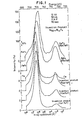
- FIG. 1 shows the profiles of soft X-ray spectra of films of Fe and Fe-Fn compounds (n: 2, 3) and those of invention films having large Kerr rotation angles respectively;
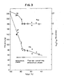
- FIG. 2 is a graph showing the peak positions of La and Lβ of Fe, the peak height ratios of Lα/Lβ and the half widths of the La in soft X-ray spectra of the invention films having large Kerr rotation angles in comparison with F, FeF2 compound and FeF3 compound;
- FIG. 3 graphically shows the Fe dependence of the saturation magnetization Ms of an Fe-B-F film and that of the average magnetic moment µFe(µB per iron atom);
- FIG. 4 diagrammatically illustrates the wavelength dependence of the
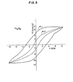
Kerr rotation angle 8K of an Fe-B-F film and the magnetic field dependence of the Kerr rotation angle θK of Fe44.0B3.6F52.4 in He-Ne laser; - FIG. 5 depicts M-H hysteresis curves of a transparent and perpendicular magnetic Fe40F60 film;
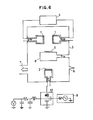
- FIG. 6 is a simplified schematic view of an opposing-target DC,Rf sputtering apparatus employed in Examples of this invention;
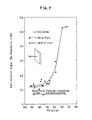
- FIG. 7 is a graph showing the Fe dependence of the Kerr rotation angles of a sputtered Fe-B film and an Fe-B-F film produced using Fe90B10, both, in He-Ne laser;
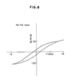
- FIG. 8 illustrates a θK-H hysteresis curve of a transparent and perpendicular magnetic film of Fe40F60 in He-Ne laser;
- FIG. 9 is a plane view of a disks made of glass or a resin;
- FIG. 10 shows a 8K-H hysteresis curve of a perpendicular magnetic TbFeCo film;
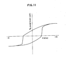
- FIG. 11 depicts a 8K-H hysteresis curve of a perpendicular magnetic film of Fe40F60 + TbFeCo;
- FIG. 12 schematically illustates a system making use of a medium of this invention, which permits writing by a perpendicular magnetic recording head and reading by optical head;
- FIG. 13 illustrates θF-H hysteresis curves of an Fe-F film upon optical transmission of He-Ne laser therethrough and the magnetic field dependence of magnetization; and
- FIG. 14 shows magnetic characteristics of an Ni-F film and its θF-H hysteresis curve.
- The present invention will now be described in detail below.
- The above halogen-containing thin transparent film and perpendicular magnetic thin transparent film may have various crystalline structures. Namely, they may take amorphous, crystalline or metastable state. Since their interatomic bonds do not give substantial influence to the 3d orbital, they do not give any large influence to the magnetic characteristics of the transparent films. The above thin films show therefore metallic and ferromagnetic properties and these films have optical transparency owing to the halogen element or elements, has transparency to light. Owing to their metallic nature, they can give large reflectivity. By the addition of rotations of light-deflecting angles both at the surface of the films and inside the films upon reflection, they exhibit large Kerr rotation angles.
- The above films having the large Kerr rotation angles are applicable as optical modulators, which make use of the magneto-optical Kerr effect in magneto- optics, in integrated optical circuits such as optical switches, optical isolators and circulators. In magneto-optical disk memories making use of the magneto-optical Kerr effect, Kerr rotation angles can be increased further by using a multilayer structure which exhibits both magneto-optical Kerr effect and Faraday effect in combination. In view of such high applicability, they are indispensable for the present and future optical technology.
- As properties characteristic to the halogen-containing thin transparent film of this invention, the following properties may be mentioned.
- a) Its chemical bonds do not cause any substantial chemical shift of the La ray peak in a soft X-ray emission spectrum even if the element F is contained as much as 50 at.% or so.
- b) Accordingly, it can produce large magnetization. As a material capable of showing optical transparency, its magnetization is at least 60 emu/g at an F content of about 50 at.%. The average magnetic moment µB per Fe atom is about 1ug.
- c) Kerr rotation angle increases in proportion to the content of F. At an F content of 50 at.%, a rotation angle of 0.5° is shown in the wavelength range of He-Ne laser. A rotation angle as large as 0.7° was exhibited at 700 - 800 nm.
The perpendicular magnetic thin transparent film of this invention has the following property d) in addition to the above-described properties a) through c). - d) A film having perpendicular magnetic anisotropy can be formed by adjusting its production conditions, i.e., the ultimate vacuum of the backing pressure, the partial pressure of Ar, the sputtering temperature and the sputtering power.
- The above properties a) - d) will hereinafter be described in further detail.
- a) Halogen atoms react with any metal and also react with many non-metals. Of such halogen atoms, F is most reactive. The reactivity decreases as the atomic number increases. This high reactivity of the element F is attributed to the low energy of an F-F bond, its extremely strong oxidizing power and its high electronegativity.
- Due to this violent reactivity, halogen gases have not been contained at varied contents in metals. They have been used primarily as reactive gases in the dry etching technique or as carrier gases in the chemical vapor deposition process.
- When bonded chemically with a metal, a halogen element is converted into crystals having optical transparency. It is however the general characteristics of halogen compounds that like FeF2 and FeF3 shown in FIG. 1, a considerable peak shift of La is observed along with an increase to its peak width, significant influence is given to the 3d level of the electron state of Fe, and antiferromagnetism or parasitic ferromagnetism is exhibited.
- It is a characteristic feature of the production process of this invention that the La peak shift is small. The profiles of La and Lβ peaks in a soft X-ray emission spectrum of Fe in the halogen-containing thin transparent film of this invention are shown for various halogen contents in FIG. 1. FIG. 2 illustrates the shifts of La and Lβ peaks, the ratios of La peak heights to corresponding Lβ peak heights, namely, Lβ/Lα (height ratio ), and the F-content dependence of the half widths of the La. peaks, in comparison with the corresponding data of Fe, FeF2 and FeF3.
- As apparent from FIG. 1 and FIG. 2, the halogen-containing thin transparent film of this invention, for example, the Fe-B-F film shows the same La and Lβ peak positions and peak half width as Fe and the height ratio of Lβ/Lα increases as the content of the element F becomes higher. It is hence appreciated that no La peak shift occurred unlike FeF2 or FeF3. This means that the chemical bond Fe-F are formed between their respective outermost orbitals and the inner orbital which affects considerable on the magneto-optical effect, namely, the 3d orbital is not affected. The halogen-containing thin transparent film of this invention is therefore ferromagnetic and exhibits large magneto-optical effect owing, for example, to the action of the magnetic moment of the electron on the orbital of the 3d level.
- b) FIG. 3 shows the Fe dependence of the saturation magnetization Ms of the Fe-B-F film and that of the average magnetic moment µFe(µB per iron atom). Owing to the existence of such an electron state as described above in a), good optical transparency and high magnetic characteristics are exhibited even at an F content of about 50 at.%. The element F is an amorphous-forming element, and no large variations take place with respect to Curie temperature and cyrstallization temperature even when the F content increases. However, the saturation magnetization Ms becomes smaller as the F content drops. When the fluoride begins to grow in the amorphous phase, the degree of decrease of Ms is reduced. µFe (at 77 K) decreases in the amorphous phase as the F content increases. However, µFe reaches about 1µB when a fluoride phase appears.
This is a typical reflection of Fe-F bonds. - c) Owing to such a characteristic electron state of metal-gas elements as described above, the quantity of reflected light is large, the Kerr rotation angle increases as the content of F increases. At F contents of 40 - 50 at.%, high Kerr rotation angles were exhibited, namely, 8K = 0.5° in the wavelength range of He-Ne laser and 8K = 0.7° at 700 - 800 nm.
- FIG. 4 shows the wavelength dependence of the Kerr rotation angles 8K of Fe-B-F films by way of example. The films depicted in FIG. 4 are in-plane magnetizable films. Regarding their dependence on magnetic field, their rotation angles at 633 nm increase as the magnetic field becomes stronger. The higher the content of F, the higher the θK. 8K tends to become still higher on the side of longer wavelengths. The special Fe-F bond and the optical transparency of the element F seem to be combined together so that the resulting rotations at the surface of the film and inside the film probably contribute to the production of a large Kerr rotation angle. In the case of oxides, Kerr rotation angles by reflection without reflective plates are usually extremely small. The film of this invention shows a large Kerr rotation angle without any reflecting plate.
- d) Turning next to the perpendicular magnetic thin transparent film, it is an in-plane magnetizable film. It can however be obtained as a transparent film having perpendicular magnetic anisotropy provided that film-forming conditions are chosen suitably. In FIG. 5, M-H hysteresis curves of an Fe40F60 film is shown by way of example. Out of the in-plane and perpendicular directions, anisotropy is shown clearly in the perpendicular direction. Vertical magnetic anisotropy energy has a positive value.
- The process of this invention for the production of the halogen-containing thin transparent film makes use of reactive film formation process. This process is carried out in a state in which at least one of the components of a compound to be formed in the form of a thin film is contained in a vapor phase.
- A reactive Rf,DC sputtering apparatus may be used by way of example as a production apparatus. This reactive sputtering involves both physical sputtering and chemical sputtering. On a substrate, a thin film is formed at a low temperature and in a state that the energy of bombardment to the substrate is low. Because of reactive sputtering, it is possible to vary the gas partial pressure and the output to the target so that optically-transparent films of various structures, namely, in amorphous, crystalline and metastable forms can be obtained. It is also possible to adjust the degree of chemical bonds (ionization degree) into various levels.
- A halogen compound is decomposed in the production process of this invention, whereby a halogen gas and its compound gas are produced as reactive gases. These halogen gases are then reacted with a metal plasma which may contain the same kind of halogen gas, so that the resulting compound is allowed to deposit as a thin film on the substrate. This process has merits that the danger of introduction of a highly-reactive halogen gas through a piping system is avoided and inclusion of impurities is also prevented.
- The present invention will hereinafter be described specifically by the following Examples.
- An opposing-target DC,Rf sputtering apparatus depicted in FIG. 6 was used. Fe90B10 (at.%) was attached to opposing DC targets 1, which were cooled with water.
- An
Rf target 2 had been produced by press forming a halogen compound, FeF3. After evacuating the interior of a vacuum compartment 3 to 5 x 10⁻⁷ Torr, Ar gas was introduced to raise the interior pressure of the vacuum compartment to 1 x 10⁻²,Torr. There are also shown aDC power supply 4, asubstrate 5, afeed port 6 for the argon gas, a pumpingport 7, a water-cooledsubstrate holder 8, anRf power supply 9, and amatching circuit 10. - By setting the Rf output for the production of the halogen gas at 300 W for example and changing the DC output of the opposing DC Fe90B10 targets 1, it was possible to vary with ease the contents of B and F in an optically-transparent film to be formed on the
substrate 5. Their crystalline structures were amorphous at F contents of 25 at.% and lower but peaks corresponding to fluoride crystals appeared in x-ray diffractions at F contents above 25 at.%. - FIG. 7 shows the Fe dependence of the Kerr rotation angles of sputtered Fe-B films and that of the Kerr rotation angles of Fe-B-F films produced from Fe90B10, both, in He-Ne laser. At about 50 at.% Fe, 8K of 0.5° was exhibited.
- The value of θK can be improved by incorporating Co and/or one or more of the elements recited in the claims in the Fe-B-F film.
- Using such a sputtering apparatus as depicted in FIG. 6, the water-cooled
substrate holder 8 was turned over 180° so that thesubstrate 5 was set on the side of theRf target 2. - The
Rf target 2 was produced by press-forming the halogen compound, FeF3, by way of example. After evacuating the interior of the vacuum compartment 3 to 5 x 10⁻⁷ Torr, Ar gas was introduced to raise the interior pressure of the vacuum compartment to 5 x 10⁻³ Torr. - By setting the Rf output of the press-formed FeF3 target at 250 W for example, a sputtered film was allowed to deposit on the
substrate 5. Magnetic characteristics of the thus-obtained sputtered film were measured by VSM (vibrating sample magnetometer). As a result, there was obtained a film having perpendicular magnetic anisotropy, namely, large anisotropy in a direction perpendicular to the plane of the film as depicted by way of example in FIG. 5. In addition, the magnetic field dependence of the Kerr rotation angle upon reflection by the Fe-F film was determined. A 8K-H hysteresis curve as shown in FIG. 8 was obtained. The value of θK was found to be 0.32° in He-Ne laser. This value was improved further on the side of longer wavelengths. It was also improved when a reflective plate was attached. - The Faraday rotation angle of an Fe-F film upon transmission of He-Ne laser therethrough and the magnetic field dependence of magnetization were then determined. A 8F-H hysteresis curve was obtained as shown in FIG. 13. The Faraday coefficient was found to be 2.2 x 10⁴ deg/cm. The shape of the θF-H hysteresis curve was similar to that of the M-H curve for Ml, which is shown above the θF-H hysteresis in the same figure. A 8K-H hysteresis curve was also obtained with a reflective plate. The value of θK was found to be 2.20° in a magnetic field of 7 kOe.
- The perpendicular magnetic anisotropy energy and 8K can be improved by incorporating one or more of Co and other elements, which are recited in the claims, in the Fe-F film.
- In the same manner as in Example 2, NiF2 was press-formed as an exemplary halogen compound to provide the
Rf target 2. After depressurizing the interior of the vacuum compartment 3 to 5 x 10⁻⁷ Torr, Ar gas was introduced to adjust the interior pressure of the compartment to 5 x 10 -3 Torr. - While maintaining the Rf output of the press-formed NiF2 powder target, for example, at 250 W, a sputtered film was allowed to deposit on the
substrate 5. Magnetic characteristics and Faraday rotation angle of the resultant sputtered film were measured. There was obtained a perpendicular magnetic film which had positive perpendicular magnetic anisotropy energy in the perpendicular direction of the surface of the film as illustrated in FIG. 14. In addition, the magnetic field dependence of the Faraday rotation angle of the Ni-F film at He-Ne laser light source was determined. The magnetic field dependence of OF is shown in the lower part of FIG. 14. It has a similar figure as the M-H hysteresis curve for M⊥ illustrated in the upper part of FIG. 14. - A reflective plate was applied to the Ni-F film and the K err rotation angle was measured. It was found to be 1.21° in He-Ne laser. The Kerr rotation angle was found to be 0.7 at H=0.
- The perpendicular magnetic anisotropy energy and 8K can be improved by incorporating one or more of Fe, Co and other elements, which are recited in the claims, in the Ni-F film.
- Shown as Examples in the following table are the compositions of thin film samples, which contain halogen elements, fall in composition within the composition recited in Claim 1, show optical transparency and perpendicular magnetic anisotropy and have large Kerr rotation angles, along with their Kerr rotation angles.

- Using the sputtering apparatus shown in FIG. 6, a glass or resin disk of 200 mm x 35 mm x 1.2 mmt depicted in FIG. 9 were set on the water-cooled
substrate holder 8. The disk was rotated at 20 - 200 rpm from the outside of the vacuum compartment 3. FeF3 powder containing fine particulate metals such as Co, Bi and Te was placed by way of example on the Rf electrode, so that an optically-transparent and perpendicular magnetic film was caused to deposit to 0 500 A on the glass disk. Thereafter, TbFeCo was placed 0 on the Rf electrode so as to deposit it to 1500 A on the film. A protective plate of SiO was then caused to deposit to 100 A on the TbFeCo film. - A magneto-optical disk produced in the above manner had the following characteristics.
- A θK-H hysteresis curve of a perpendicular magnetic film of TbFeCo alone is shown in FIG. 10. The hysteresis of 8K has a similar figure to the figure of the Ms-H hysteresis curve measured by VSM, thereby indicating that the TbFeCo film was a perpendicular magnetic film. Its Kerr rotation angle8K was 0.2 in He-Ne laser.
- An optically-transparent and perpendicular magnetic film of 500 A according to this invention was then caused to deposit in advance on the disk, followed by deposition of a TbFeCo film having a thickness of 1500 A. The θK-H hystersis curve of the thus-produced film substantially reflected the hysteresis of the8K-H curve of TbFeCo as shown in FIG. 11. Its 8Kwas found to be 0.7° in the wavelength range of He-Ne laser. This value increased further on the side of longer wavelengths. The S/N ratio of the thus-produced magneto-optical disk was then determined. An LED (wavelength: 800 nm) was used as a light source. The S/N ratio was found to be at least 60 dB.
- As has been demonstrated above, the optically-transparent and perpendicular magnetic film of this invention is effective in enhancing the Kerr rotation angle so that the value of θK increases.
- Use of an optically-transparent and perpendicular magnetic film of this invention as an optical recording medium will next be described by way of example.
- FIG. 12 shematically illustrates a system making use of the medium of this invention, which permits writing by a perpendicular magnetic head and optical reading (perpendicular magnetic recording and magneto-optical reading system).
Numeral 11 indicates a glass disk or a resin disk. Designated atnumeral 12 is the optically-transparent and perpendicular magnetic film of this invention. Designated atnumeral 13 is a perpendicular magnetic film of a rare earth element-Fe-Co system. This film may not be required in some instances. There is also shown aplate 14, which serves not only as a reflective plate but also as a plate for lubricating the slide of a perpendicularmagnetic recording head 15. - The above system will next be described in detail. This system has been developed in order to improve the drawbacks of the present magneto-optical recording system. The optical disks 11 - 14 are rotated at a high speed of 1,000 - 1,800 rpm. The perpendicular 0
magnetic head 15 is spaced with a gap of about 50 A from theprotective plate 14. High-frequency writing is performed in thefilms 12, 1 3 as recording layers by thehead 15. Although numeral 13 indicates the perpendicular magnetic film of the rare earth element-Fe-Co system, thefilm 12 has the same properties as thefilm 13. Information may therefore be written primarily in the optically-transparent and perpendicularmagnetic film 12. Written magnetic domains are more stable when written in the multilayer film. The thus-written magnetic domains are then read out by a laser beam as shown in FIG. 12. The laser system is used exclusively for reading. Accordingly, the output of a semiconductor laser may be low and the stability of the laser beam source is high. In addition, the temperature of the recording medium do not increase substantially because it is no longer required to perform recording at the compensation or Curie point. The stability of the recording medium has hence been improved significantly compared with the present magneto-optical recording system. Since it is a recording method not accompained by thermal diffusion, the writing, reading and over-writing speeds can be increased to those of current hard disks. - It is also possible to solve the drawback of the perpendicular magnetic recording method. It is the drawback of the vertical magnetic recording method that a high S/N ratio may not be fully ensured upon reading when writing bit areas are rendered smaller. The system making use of the present invention however permits use of small bit areas because the reading is performed magneto-optically. The recording density can therefore be maintained at substantially the same level as those of magneto-optical systems presently in use.
- As has been described above, the use of the optically-transparent film of this invention, which has perpendicular magnetic anisotropy, makes it possible to complete a highly stable recording system which features high-speed and high-density writing, high-speed reading and high-speed erasing.
- Having now fully described the invention, it will be apparent to one of ordinary skill in the art that many changes and modifications can be made thereto without departing from the spirit or scope of the invention as set forth herein.
Claims (3)
which comprises reacting a halogen or halogen-containing gas, which has occurred as a result of decomposition of a halogen compound, with a metal plasma or halogen-containing metal plasma and allowing the resultant compound to deposit as a thin film on a substrate.
Applications Claiming Priority (2)
| Application Number | Priority Date | Filing Date | Title |
|---|---|---|---|
| JP168093/86 | 1986-07-18 | ||
| JP61168093A JPS63107008A (en) | 1986-07-18 | 1986-07-18 | Thin-film having large kerr's angle of rotation and manufacture thereof |
Publications (3)
| Publication Number | Publication Date |
|---|---|
| EP0253282A2 true EP0253282A2 (en) | 1988-01-20 |
| EP0253282A3 EP0253282A3 (en) | 1989-11-15 |
| EP0253282B1 EP0253282B1 (en) | 1992-11-04 |
Family
ID=15861714
Family Applications (1)
| Application Number | Title | Priority Date | Filing Date |
|---|---|---|---|
| EP87109803A Expired EP0253282B1 (en) | 1986-07-18 | 1987-07-07 | Thin-film having large kerr rotation angle and production process thereof |
Country Status (4)
| Country | Link |
|---|---|
| US (1) | US4925742A (en) |
| EP (1) | EP0253282B1 (en) |
| JP (1) | JPS63107008A (en) |
| DE (1) | DE3782460T2 (en) |
Cited By (2)
| Publication number | Priority date | Publication date | Assignee | Title |
|---|---|---|---|---|
| EP0464941A1 (en) * | 1990-07-02 | 1992-01-08 | Eastman Kodak Company | Phase-change optical recording media |
| EP0529795A1 (en) * | 1991-07-22 | 1993-03-03 | Canon Kabushiki Kaisha | Magnetooptic recording medium |
Families Citing this family (6)
| Publication number | Priority date | Publication date | Assignee | Title |
|---|---|---|---|---|
| JP2612966B2 (en) * | 1990-04-13 | 1997-05-21 | インターナショナル・ビジネス・マシーンズ・コーポレーション | Amorphous uranium alloy, magneto-optical storage medium and magneto-optical storage system using the same |
| US5534360A (en) * | 1991-12-13 | 1996-07-09 | International Business Machines Corporation | Amorphous uranium alloy and use thereof |
| US5493220A (en) * | 1993-03-05 | 1996-02-20 | Northeastern University | Magneto-optic Kerr effect stress sensing system |
| US5631559A (en) * | 1993-03-05 | 1997-05-20 | Northeastern University | Method and apparatus for performing magnetic field measurements using magneto-optic kerr effect sensors |
| US5968678A (en) * | 1995-08-31 | 1999-10-19 | Sanyo Electric., Ltd. | Magneto-optical recording medium and manufacturing method thereof |
| KR100468827B1 (en) * | 1998-04-03 | 2005-08-31 | 삼성전자주식회사 | Amorphous light rare earth-alloy and manufacturing method of transition metal and semimetal |
Citations (2)
| Publication number | Priority date | Publication date | Assignee | Title |
|---|---|---|---|---|
| US3572894A (en) * | 1968-12-27 | 1971-03-30 | Bell Telephone Labor Inc | Ferric fluoride devices |
| JPS6286807A (en) * | 1985-10-14 | 1987-04-21 | Res Dev Corp Of Japan | Ferromagnetic light transmission film and its manufacture |
Family Cites Families (9)
| Publication number | Priority date | Publication date | Assignee | Title |
|---|---|---|---|---|
| US2945744A (en) * | 1958-02-14 | 1960-07-19 | Bell Telephone Labor Inc | Magnetic materials |
| US3676082A (en) * | 1967-05-19 | 1972-07-11 | Rca Corp | Magnetic compositions |
| US3485551A (en) * | 1967-07-17 | 1969-12-23 | Bell Telephone Labor Inc | Rubidium iron fluoride magneto-optical devices |
| US3399957A (en) * | 1968-01-16 | 1968-09-03 | Ibm | Magnetic materials and process of preparation |
| US3527577A (en) * | 1968-05-03 | 1970-09-08 | Ibm | Magneto-optical materials |
| JPS5388014A (en) * | 1977-01-13 | 1978-08-03 | Hoya Glass Works Ltd | Faraday rotation glass |
| JPS60133542A (en) * | 1983-12-21 | 1985-07-16 | Olympus Optical Co Ltd | Production of magnetic recording medium |
| JPS60253039A (en) * | 1984-05-30 | 1985-12-13 | Toshiba Corp | Thin film magnetic recording medium |
| JPH0573042A (en) * | 1991-09-17 | 1993-03-26 | Dainippon Printing Co Ltd | Electronic score display device |
-
1986
- 1986-07-18 JP JP61168093A patent/JPS63107008A/en active Pending
-
1987
- 1987-07-07 DE DE8787109803T patent/DE3782460T2/en not_active Expired - Lifetime
- 1987-07-07 EP EP87109803A patent/EP0253282B1/en not_active Expired
-
1988
- 1988-10-18 US US07/259,489 patent/US4925742A/en not_active Expired - Lifetime
Patent Citations (2)
| Publication number | Priority date | Publication date | Assignee | Title |
|---|---|---|---|---|
| US3572894A (en) * | 1968-12-27 | 1971-03-30 | Bell Telephone Labor Inc | Ferric fluoride devices |
| JPS6286807A (en) * | 1985-10-14 | 1987-04-21 | Res Dev Corp Of Japan | Ferromagnetic light transmission film and its manufacture |
Non-Patent Citations (1)
| Title |
|---|
| PATENT ABSTRACTS OF JAPAN, vol. 11, no. 288 (E-542)[2735], 17th September 1987; & JP-A-62 086 807 (RES. DEV. CORP. OF JAPAN) 21-04-1987 * |
Cited By (3)
| Publication number | Priority date | Publication date | Assignee | Title |
|---|---|---|---|---|
| EP0464941A1 (en) * | 1990-07-02 | 1992-01-08 | Eastman Kodak Company | Phase-change optical recording media |
| EP0529795A1 (en) * | 1991-07-22 | 1993-03-03 | Canon Kabushiki Kaisha | Magnetooptic recording medium |
| US5370945A (en) * | 1991-07-22 | 1994-12-06 | Canon Kabushiki Kaisha | Magnetooptic recording medium |
Also Published As
| Publication number | Publication date |
|---|---|
| EP0253282A3 (en) | 1989-11-15 |
| DE3782460D1 (en) | 1992-12-10 |
| JPS63107008A (en) | 1988-05-12 |
| DE3782460T2 (en) | 1993-03-18 |
| US4925742A (en) | 1990-05-15 |
| EP0253282B1 (en) | 1992-11-04 |
Similar Documents
| Publication | Publication Date | Title |
|---|---|---|
| US5747136A (en) | High-density magneto-optic disk and method of manufacturing the same | |
| US4880694A (en) | Magneto-optical recording material | |
| US5112701A (en) | Magneto-optic recording media and process for producing the same | |
| US5660929A (en) | Perpendicular magnetic recording medium and method of producing same | |
| JPH0740380B2 (en) | Magneto-optical recording material | |
| EP0135322B2 (en) | An optical magnetic recording member | |
| US4925742A (en) | Thin-film having large Kerr rotation angle and production process thereof | |
| JPS6115308A (en) | Photomagnetic recording material | |
| US4995024A (en) | Magneto-optical recording element | |
| US5639563A (en) | Magneto-optical recording medium | |
| US5501913A (en) | Garnet polycrystalline film for magneto-optical recording medium | |
| US5100741A (en) | Magneto-optic recording systems | |
| JPS63179435A (en) | Thin film magnetic recording medium | |
| KR920007319B1 (en) | Magneto-optical recording media | |
| US5529854A (en) | Magneto-optic recording systems | |
| JPH0570922B2 (en) | ||
| JP3007239B2 (en) | Garnet double layer film for magneto-optical recording medium and magneto-optical recording disk | |
| JP2829321B2 (en) | Magneto-optical recording medium | |
| JPS62112252A (en) | Photomagnetic recording medium | |
| JP2876062B2 (en) | Magnetic film | |
| Das et al. | Thin films for secondary data storage | |
| JP3022642B2 (en) | Method for manufacturing magneto-optical recording medium | |
| JPH0536134A (en) | Magneto-optical recording medium | |
| Hashimoto et al. | Ultrathin Co/Pt and Co/Pd new magneto-optical recording media | |
| JPS62267949A (en) | Magneto-optical recording medium |
Legal Events
| Date | Code | Title | Description |
|---|---|---|---|
| PUAI | Public reference made under article 153(3) epc to a published international application that has entered the european phase |
Free format text: ORIGINAL CODE: 0009012 |
|
| AK | Designated contracting states |
Kind code of ref document: A2 Designated state(s): DE FR GB NL |
|
| PUAL | Search report despatched |
Free format text: ORIGINAL CODE: 0009013 |
|
| AK | Designated contracting states |
Kind code of ref document: A3 Designated state(s): DE FR GB NL |
|
| 17P | Request for examination filed |
Effective date: 19900118 |
|
| 17Q | First examination report despatched |
Effective date: 19920116 |
|
| GRAA | (expected) grant |
Free format text: ORIGINAL CODE: 0009210 |
|
| AK | Designated contracting states |
Kind code of ref document: B1 Designated state(s): DE FR GB NL |
|
| REF | Corresponds to: |
Ref document number: 3782460 Country of ref document: DE Date of ref document: 19921210 |
|
| ET | Fr: translation filed | ||
| ET1 | Fr: translation filed ** revision of the translation of the patent or the claims | ||
| PLBE | No opposition filed within time limit |
Free format text: ORIGINAL CODE: 0009261 |
|
| STAA | Information on the status of an ep patent application or granted ep patent |
Free format text: STATUS: NO OPPOSITION FILED WITHIN TIME LIMIT |
|
| 26N | No opposition filed | ||
| REG | Reference to a national code |
Ref country code: GB Ref legal event code: IF02 |
|
| PGFP | Annual fee paid to national office [announced via postgrant information from national office to epo] |
Ref country code: NL Payment date: 20060714 Year of fee payment: 20 Ref country code: FR Payment date: 20060714 Year of fee payment: 20 Ref country code: DE Payment date: 20060714 Year of fee payment: 20 |
|
| PGFP | Annual fee paid to national office [announced via postgrant information from national office to epo] |
Ref country code: GB Payment date: 20060720 Year of fee payment: 20 |
|
| PG25 | Lapsed in a contracting state [announced via postgrant information from national office to epo] |
Ref country code: NL Free format text: LAPSE BECAUSE OF EXPIRATION OF PROTECTION Effective date: 20070707 |
|
| REG | Reference to a national code |
Ref country code: GB Ref legal event code: PE20 |
|
| NLV7 | Nl: ceased due to reaching the maximum lifetime of a patent |
Effective date: 20070707 |
|
| PG25 | Lapsed in a contracting state [announced via postgrant information from national office to epo] |
Ref country code: GB Free format text: LAPSE BECAUSE OF EXPIRATION OF PROTECTION Effective date: 20070706 |