EP0253268A1 - Sonde à ultrasons - Google Patents
Sonde à ultrasons Download PDFInfo
- Publication number
- EP0253268A1 EP0253268A1 EP87109728A EP87109728A EP0253268A1 EP 0253268 A1 EP0253268 A1 EP 0253268A1 EP 87109728 A EP87109728 A EP 87109728A EP 87109728 A EP87109728 A EP 87109728A EP 0253268 A1 EP0253268 A1 EP 0253268A1
- Authority
- EP
- European Patent Office
- Prior art keywords
- transducer element
- casing
- ultrasonic
- motor
- ultrasonic probe
- Prior art date
- Legal status (The legal status is an assumption and is not a legal conclusion. Google has not performed a legal analysis and makes no representation as to the accuracy of the status listed.)
- Granted
Links
- 239000000523 sample Substances 0.000 title claims description 73
- 230000005540 biological transmission Effects 0.000 claims abstract description 10
- 238000003780 insertion Methods 0.000 claims abstract description 9
- 230000037431 insertion Effects 0.000 claims abstract description 9
- 239000002184 metal Substances 0.000 claims description 4
- 229920003002 synthetic resin Polymers 0.000 claims description 2
- 239000000057 synthetic resin Substances 0.000 claims description 2
- 230000007246 mechanism Effects 0.000 abstract description 8
- 239000007788 liquid Substances 0.000 description 9
- 210000000056 organ Anatomy 0.000 description 7
- 230000008054 signal transmission Effects 0.000 description 6
- 230000008878 coupling Effects 0.000 description 3
- 238000010168 coupling process Methods 0.000 description 3
- 238000005859 coupling reaction Methods 0.000 description 3
- 238000010586 diagram Methods 0.000 description 3
- 230000033001 locomotion Effects 0.000 description 3
- 238000000034 method Methods 0.000 description 3
- 230000008569 process Effects 0.000 description 3
- 230000026676 system process Effects 0.000 description 3
- 230000004913 activation Effects 0.000 description 2
- 238000004519 manufacturing process Methods 0.000 description 2
- 238000007789 sealing Methods 0.000 description 2
- 210000001835 viscera Anatomy 0.000 description 2
- CDQSJQSWAWPGKG-UHFFFAOYSA-N butane-1,1-diol Chemical compound CCCC(O)O CDQSJQSWAWPGKG-UHFFFAOYSA-N 0.000 description 1
- 230000008859 change Effects 0.000 description 1
- 239000011810 insulating material Substances 0.000 description 1
- 239000000463 material Substances 0.000 description 1
- 230000004048 modification Effects 0.000 description 1
- 238000012986 modification Methods 0.000 description 1
- 230000003287 optical effect Effects 0.000 description 1
- 230000004044 response Effects 0.000 description 1
- XLYOFNOQVPJJNP-UHFFFAOYSA-N water Substances O XLYOFNOQVPJJNP-UHFFFAOYSA-N 0.000 description 1
Images


Classifications
-
- A—HUMAN NECESSITIES
- A61—MEDICAL OR VETERINARY SCIENCE; HYGIENE
- A61B—DIAGNOSIS; SURGERY; IDENTIFICATION
- A61B8/00—Diagnosis using ultrasonic, sonic or infrasonic waves
- A61B8/12—Diagnosis using ultrasonic, sonic or infrasonic waves in body cavities or body tracts, e.g. by using catheters
-
- A—HUMAN NECESSITIES
- A61—MEDICAL OR VETERINARY SCIENCE; HYGIENE
- A61B—DIAGNOSIS; SURGERY; IDENTIFICATION
- A61B8/00—Diagnosis using ultrasonic, sonic or infrasonic waves
- A61B8/44—Constructional features of the ultrasonic, sonic or infrasonic diagnostic device
- A61B8/4444—Constructional features of the ultrasonic, sonic or infrasonic diagnostic device related to the probe
- A61B8/445—Details of catheter construction
-
- A—HUMAN NECESSITIES
- A61—MEDICAL OR VETERINARY SCIENCE; HYGIENE
- A61B—DIAGNOSIS; SURGERY; IDENTIFICATION
- A61B8/00—Diagnosis using ultrasonic, sonic or infrasonic waves
- A61B8/44—Constructional features of the ultrasonic, sonic or infrasonic diagnostic device
- A61B8/4444—Constructional features of the ultrasonic, sonic or infrasonic diagnostic device related to the probe
- A61B8/4461—Features of the scanning mechanism, e.g. for moving the transducer within the housing of the probe
- A61B8/4466—Features of the scanning mechanism, e.g. for moving the transducer within the housing of the probe involving deflection of the probe
-
- A—HUMAN NECESSITIES
- A61—MEDICAL OR VETERINARY SCIENCE; HYGIENE
- A61B—DIAGNOSIS; SURGERY; IDENTIFICATION
- A61B8/00—Diagnosis using ultrasonic, sonic or infrasonic waves
- A61B8/44—Constructional features of the ultrasonic, sonic or infrasonic diagnostic device
- A61B8/4483—Constructional features of the ultrasonic, sonic or infrasonic diagnostic device characterised by features of the ultrasound transducer
- A61B8/4494—Constructional features of the ultrasonic, sonic or infrasonic diagnostic device characterised by features of the ultrasound transducer characterised by the arrangement of the transducer elements
-
- G—PHYSICS
- G01—MEASURING; TESTING
- G01S—RADIO DIRECTION-FINDING; RADIO NAVIGATION; DETERMINING DISTANCE OR VELOCITY BY USE OF RADIO WAVES; LOCATING OR PRESENCE-DETECTING BY USE OF THE REFLECTION OR RERADIATION OF RADIO WAVES; ANALOGOUS ARRANGEMENTS USING OTHER WAVES
- G01S15/00—Systems using the reflection or reradiation of acoustic waves, e.g. sonar systems
- G01S15/88—Sonar systems specially adapted for specific applications
- G01S15/89—Sonar systems specially adapted for specific applications for mapping or imaging
- G01S15/8906—Short-range imaging systems; Acoustic microscope systems using pulse-echo techniques
- G01S15/8934—Short-range imaging systems; Acoustic microscope systems using pulse-echo techniques using a dynamic transducer configuration
- G01S15/8936—Short-range imaging systems; Acoustic microscope systems using pulse-echo techniques using a dynamic transducer configuration using transducers mounted for mechanical movement in three dimensions
-
- G—PHYSICS
- G01—MEASURING; TESTING
- G01S—RADIO DIRECTION-FINDING; RADIO NAVIGATION; DETERMINING DISTANCE OR VELOCITY BY USE OF RADIO WAVES; LOCATING OR PRESENCE-DETECTING BY USE OF THE REFLECTION OR RERADIATION OF RADIO WAVES; ANALOGOUS ARRANGEMENTS USING OTHER WAVES
- G01S15/00—Systems using the reflection or reradiation of acoustic waves, e.g. sonar systems
- G01S15/88—Sonar systems specially adapted for specific applications
- G01S15/89—Sonar systems specially adapted for specific applications for mapping or imaging
- G01S15/8906—Short-range imaging systems; Acoustic microscope systems using pulse-echo techniques
- G01S15/8934—Short-range imaging systems; Acoustic microscope systems using pulse-echo techniques using a dynamic transducer configuration
- G01S15/8938—Short-range imaging systems; Acoustic microscope systems using pulse-echo techniques using a dynamic transducer configuration using transducers mounted for mechanical movement in two dimensions
- G01S15/894—Short-range imaging systems; Acoustic microscope systems using pulse-echo techniques using a dynamic transducer configuration using transducers mounted for mechanical movement in two dimensions by rotation about a single axis
-
- G—PHYSICS
- G01—MEASURING; TESTING
- G01S—RADIO DIRECTION-FINDING; RADIO NAVIGATION; DETERMINING DISTANCE OR VELOCITY BY USE OF RADIO WAVES; LOCATING OR PRESENCE-DETECTING BY USE OF THE REFLECTION OR RERADIATION OF RADIO WAVES; ANALOGOUS ARRANGEMENTS USING OTHER WAVES
- G01S7/00—Details of systems according to groups G01S13/00, G01S15/00, G01S17/00
- G01S7/52—Details of systems according to groups G01S13/00, G01S15/00, G01S17/00 of systems according to group G01S15/00
- G01S7/52017—Details of systems according to groups G01S13/00, G01S15/00, G01S17/00 of systems according to group G01S15/00 particularly adapted to short-range imaging
- G01S7/52079—Constructional features
-
- G—PHYSICS
- G10—MUSICAL INSTRUMENTS; ACOUSTICS
- G10K—SOUND-PRODUCING DEVICES; METHODS OR DEVICES FOR PROTECTING AGAINST, OR FOR DAMPING, NOISE OR OTHER ACOUSTIC WAVES IN GENERAL; ACOUSTICS NOT OTHERWISE PROVIDED FOR
- G10K11/00—Methods or devices for transmitting, conducting or directing sound in general; Methods or devices for protecting against, or for damping, noise or other acoustic waves in general
- G10K11/18—Methods or devices for transmitting, conducting or directing sound
- G10K11/26—Sound-focusing or directing, e.g. scanning
- G10K11/35—Sound-focusing or directing, e.g. scanning using mechanical steering of transducers or their beams
- G10K11/352—Sound-focusing or directing, e.g. scanning using mechanical steering of transducers or their beams by moving the transducer
- G10K11/355—Arcuate movement
Definitions
- This invention relates to an ultrasonic probe usable in ultrasonic systems such as medical ultrasonic diagnostic systems.
- Some medical ultrasonic diagnostic systems produce sectional images of bodies. These systems generally have ultrasonic probes which scan beams of ultrasonic wave pulses to produce sectional images of bodies. There are ultrasonic probes of the mechanically scanning type. Some ultrasonic probes are inserted into and used in coeloms of a body to produce sectional images of internal organs. As will be described hereinafter, conventional ultrasonic probes have various problems.
- an ultrasonic transducer element is supported by a member.
- a casing accommodates the transducer element and the supporting member and is filled with ultrasonic wave propagation medium. At least part of the casing forms an ultrasonic wave transmission window.
- the supporting member is rotatable about a first axis and also about a second axis. The position of the supporting member is detected.
- an ultrasonic transducer element is supported by a member.
- a casing has a first portion and a second portion.
- the first casing portion accommodates the transducer element and the supporting member and is filled with ultrasonic wave propagation medium. At least part of the first casing portion forms an ultrasonic wave transmission window.
- the second casing portion extends in rear of the first casing portion and is narrower than the first casing portion.
- the transducer element is allowed to emit and receive ultrasonic wave to and from a region extending in front of the casing with respect to a direction of insertion of the casing into a body to be examined.
- an ultrasonic transducer element is supported by a member.
- a casing has a first portion and a second portion.
- the first casing portion accommodates the transducer element and the supporting member and is filled with ultrasonic wave propagation medium. At least part of the first casing portion forms an ultrasonic wave trasmission window.
- the second casing portion extends in rear of the first casing portion and is narrower than the first casing portion.
- a sensor detects at least one condition related to operation of a mechanism driving the supporting member. .
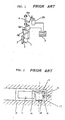
- Fig. l shows a known ultrasonic probe of the mechanically scanning type disclosed in Japanese published unexamined patent application 53-83370.
- an ultrasonic transducer element or head l is rotatably supported on a frame 3 via a shaft 2.
- the transducer element l is connected via a link 4A to a power source 5A, such as an electric motor, a pneumatic actuator, or a hydraulic actuator.
- the power source 5A can rotate the transducer element l about the shaft 2 in a limited angular range.
- a synchronizing device 7 controls operation of the power source 5A.
- the rotation of the transducer element l by the power source 5A allows a sector scan of a beam of ultrasonic wave pulses emitted from the transducer element l. This scan produces a sectoral section image of a body.
- a direction shaft 6 carrying the frame 3 is connected via a link 4B to a power source 5B, such as an electric motor, a pneumatic actuator, or a hydraulic actuator.
- the power source 5B can rotate the frame 3 about the direction shaft 6. Accordingly, at varying directions or angular positions of the frame 3, sectoral section images of the body are available.
- the synchronizing device 7 controls operation of the power source 5B.
- the transducer element drive mechanism composed of the link 4A and the power source 5A considerably limits the angle of the sector scan of the beam of ultrasonic wave pulses.
- the links 4A and 4B cause the probe to be large. Since the transducer element l and the frame 3 are subjected to reciprocating rotational movements in limited angular ranges, great mechanical vibrations tend to be generated.
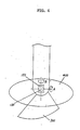
- Japanese published unexamined patent application 59-l3l339 discloses an ultrasonic probe designed to be used in coeloms of a body to produce sectional images of internal organs.
- Fig. 2 shows such a known ultrasonic probe.
- a pulse motor ll is connected to a damper l4 via a micro gear head l2 and a shaft l3.
- The, damper l4 carries an ultrasonic transducer element or head l5.
- the shaft l3 is supported by a plate l6.
- the devices ll-l6 are accommodated in a casing l7.
- the ultrasonic probe is inserted into an organ l8 of a body.
- the pulse motor ll serves to rotate the damper l4 and the transducer element l5 about the shaft l3.
- the micro gear head l2 reduces the rotational speed of the transducer element l5 in comparison with the rotational speed of the pulse motor ll.
- the rotation of the transducer element l5 by the pulse motor ll allows a sector scan of a beam of ultrasonic wave pulses emitted from the transducer element l5. This scan of the beam of ultrasonic wave pulses produces a sectoral section image of the organ l8.
- Fig. 3 shows an ultrasonic probe according to a first embodiment of this invention.
- a motor l9 and an encoder 20 are disposed within a cylindrical casing 40.
- a cable 30 containing electric leads extends into the casing 40 and is electrically connected to the motor l9 and the encoder 20.
- the cable 30 is also electrically connected to a main portion of a medical ultrasonic diagnostic system (not shown).
- Various signals are transmitted between the main portion of the diagnostic system and the motor l9, and between the main portion of the diagnostic system and the encoder 20 via the cable 30.
- a chassis 80 is disposed within a housing or container l00 fixed to the casing 40.
- An ultrasonic transducer element or head l30 is attached to an outer surface of a support l20 which is rotatably connected to the chassis 80 via a shaft ll0.
- the transducer element l30 is preferably provided with an acoustic matching layer and an acoustic lens in a known manner.
- a signal transmission device 50 preferably composed of a slip ring is mounted on the chassis 80.
- a rotary transformer (not shown) is disposed within the support l20.
- the transducer element l30 is electrically connected to the cable 30 via the signal transmission device 50, the rotary transformer, and leads (not shown). It should be noted that the rotary transformer may be replaced by a slip ring.
- the container l00 is filled with liquid ultrasonic wave propagation medium.
- An O-ring 60 provided between the chassis 80 and a shaft l90 prevents leakage of the ultrasonic wave propagation liquid.
- An O-ring 70 provided between the chassis 80 and the container l00 also prevents leakage of the ultrasonic wave propagation liquid.
- the container l00 is preferably made of a material permeable to ultrasonic waves so that the container l00 forms an ultrasonic wave transmission window. It should be noted that only a portion of the container l00 may be designed to form an ultrasonic wave transmission window.
- the motor l9 has a rotatable output shaft coaxial with the shaft l90.
- a clutch 200 provided between the motor shaft and the shaft l90 selectively connects and disconnects the shaft l90 to and from the motor shaft.
- the shaft l90 extends along a central axis of the chassis 80.
- a bevel gear 90 is fixedly mounted on a shaft 9l rotatably suppoted by the chassis 80.
- the shaft 9l extends perpendicular to the shaft l90.
- the bevel gear 90 meshes with a bevel gear l80 fixedly mounted on the shaft l90.
- a pulley l70 fixedly mounted on the shaft 9l is coupled via an endless belt l60 to a pulley l40 fixedly mounted on the shaft ll0.
- the shaft ll0 extends parallel to the shaft 9l and perpendicular to the shaft l90.
- the clutch 200 connects the shaft l90 to the motor shaft
- a rotational force is transmitted from the motor l9 to the support l20 via the motor shaft, the clutch 200, the shaft l90, the bevel gears 90 and l80, the shaft 9l, the pulley l70, the belt l60, the pulley l40, and the shaft ll0 so that the support l20 and the tranducer element l30 rotate about the shaft ll0.
- This rotation of the support l20 and the transducer element l30 is denoted by the arrow A in Fig. 4.
- the connection between the slider 230 and the motor shaft preferably includes a key coupling which allows the slider 230 to rotate together with the motor shaft and allows the slider 230 to move axially relative to the motor shaft. Since the gear 2l0 is fixed to the slider 230, the gear 2l0 rotates together with the motor shaft but is axially movable relative to the motor shaft.
- a gear 220 is secured to the chassis 80. As the gear 2l0 is moved axially by the slider 230, the gear 2l0 comes into and out of mesh with the gear 220.
- the chassis 80 is rotatably supported on the container l00 via bearings. The chassis 80 can rotate about the motor shaft and the shaft l90.
- the trasducer element l30 Since the transducer element l30 is connected to the chassis 80 via the support l20 and the shaft ll0, the trasducer element l30 rotates together with the chassis 80. In cases where the clutch 200 disconnects the motor shaft from the shaft l90, when the gear 2l0 is moved into mesh with the gear 220 and the motor l9 is activated, a rotational force is transmitted from the motor l9 to the chassis 80 so that the chassis 80 and the transducer element l30 rotate about the motor shaft and the shaft l90. This rotation of the transducer element l30 is denoted by the arrow B in Fig. 4.
- the clutch 200 is preferably of the electromagnetic type.
- the clutch 200 is electrically connected to the cable 30 via electric leads so that the clutch 200 is controllable via an electric signal outputted from the main portion of the diagnostic system.
- the clutch 200 may be controllable via a mechanical device which can be handled outside the casing 40.
- the slider 230 is preferably driven by an electric actuator or a solenoid disposed within the casing 40.
- the actuator or the solenoid is electrically connected to the cable 30 via electric leads so that the slider 230 is controllable via an electric signal outputted from the main portion of the diagnostic system.
- the slider 230 may be controllable via a mechanical device which can be handled outside the casing 40.
- the encoder 20 is associated with the motor shaft.
- the encoder 20 generates an electric signal or signals representing the angular position of the motor shaft and the rotational speed of the motor shaft. These signals are transmitted to the main portion of the diagnostic system via the cable 30.
- the encoder 20 is preferably of the optical type or the electromagnetic type generating electric pulses in accordance with the rotation of the motor shaft. Since the position of the transducer element l30 depends on the angular position of the motor shaft, the position of the transducer element l30 is detected via the signal representing the angular position of the motor shaft.
- the ultrasonic probe of Fig. 3 operates as follows.
- the ultrasonic probe is generally inserted into a coelom of a body to be examined.
- First, the operation of the ultrasonic probe will be described with respect to cases where the slider 230 is moved to a position at which the gear 2l0 separates from the gear 220, and where the clutch 200 is controlled so that the shaft l90 is coupled to the motor shaft.
- the support l20 and the transducer element l30 rotate about the shaft ll0 and in the direction denoted by the arrow A of Fig. 4.
- the main portion of the diagnostic system When the position of the transducer element l30 which is detected via the signal from the encoder 20 reaches a desired position or range, the main portion of the diagnostic system outputs an activation signal to the transducer element l30 via the cable 30, the signal transmission device 50, and the rotary transformer (not shown) within the support l20 so that the transducer element l30 is energized. Accordingly, the transducer element l30 emits a beam of ultrasonic wave pulses, which travels to the body via the ultrasonic wave propagation liquid l50 and the walls of the container l00. The body generally has uneven acoustic impedances which cause the ultrasonic wave pulses to be reflected.
- the reflected ultrasonic wave pulses return to the transducer element l30.
- the transducer element l30 converts the reflected and returned ultrasonic wave pulses into a corresponding electric signal, which is transmitted to the main portion of the diagnostic system via the rotary transformer within the support l20, the signal transmission device 50, and the cable 30.
- the main portion of the diagnostic system processes this electric signal and thereby derives a display data signal corresponding to one scanning line in a known way.
- the data signal is indicated by a display such as a cathode-ray tube.
- the previously-mentioned operation to derive a diaplay data signal corresponding one scanning line is periodically reiterated while the transducer element l30 is rotated through a desired angular range by the motor l9.
- the beam of ultrasonic wave pulses emitted from the transducer element l30 is scanned along a sector plane 300 as shown in Fig. 4, so that a corresponding sector sectional image of the body is obtained on the display.
- the main portion of the diagnostic system monitors the position of the transducer element l30 via the signal from the encoder 20 and controls the position of the transducer element l30 in accordance with the monitored information via the signal to the motor l9 in conventional closed loop control. Furthermore, the main portion of the diagnostic system controls the speed of the motor l9 in accordance with the speed signal from the encoder 20 to regulate the rotational speed of the support l20 and the transducer element l30 at a constant value.
- the angle of the sector scan of the ultrasonic wave beam is, for example, l00°.
- the sector scan angle may be 360° or other values.
- the support l20 and the transducer element l30 may be rotated in reciprocatory motion by a suitable actuator to produce a sector scan of the ultrasonic wave beam.
- the operation of the ultrasonic probe will be described with respect to cases where the clutch 200 is controlled so that the shaft l90 is disconnected from the motor shaft, and where the slider 230 is moved to a position at which the gear 2l0 meshes with the gear 220.
- the support l20 and the transducer element l30 rotate together with the chassis 80 about the motor shaft and the shaft l90 and in the direction denoted by the arrow B of Fig. 4.
- the transducer element l30 is generally prelocated so as to face in the direction perpendicular to the motor shaft and the shaft l90.
- the main portion of the diagnostic system When the position of the transducer element l30 which is detected via the signal from the encoder 20 reaches a desired position or range, the main portion of the diagnostic system outputs an activation signal to the transducer element l30 via the cable 30, the signal transmission device 50, and the rotary transformer (not shown) within the support l20 so that the transducer element l30 is energized. Accordingly, the transducer element l30 emits a beam of ultrasonic wave pulses, which travels to the body via the ultrasonic wave propagation liquid l50 and the walls of the container l00. The body generally has uneven acoustic impedances which cause the ultrasonic wave pulses to be reflected.
- the reflected ultrasonic wave pulses return to the transducer element l30.
- the transducer element l30 converts the reflected and returned ultrasonic wave pulses into a corresponding electric signal, which is transmitted to the main portion of the diagnostic system via the rotary transformer within the support l20, the signal transmission device 50, and the cable 30.
- the main portion of the diagnostic system processes this electric signal and thereby derives a display data signal corresponding to one scanning line in a known way.
- the data signal is indicated by the display.
- the previously-mentioned operation to derive a diaplay data signal corresponding one scanning line is periodically reiterated while the transducer element l30 is rotated through an angle of 360° by the motor l9.
- the beam of ultrasonic wave pulses emitted from the transducer element l30 is scanned along a circular plane 400 as shown in Fig. 4, so that a corresponding circular sectional image of the body is obtained on the display.
- the main portion of the diagnostic system monitors the position of the transducer element l30 via the signal from the encoder 20 and controls the position of the transducer element l30 in accordance with the monitored information via the signal to the motor l9 in conventional closed loop control. Furthermore, the main portion of the diagnostic system controls the speed of the motor l9 in accordance with the speed signal from the encoder 20 to regulate the rotational speed of the transducer element l30 at a constant value. It should be noted that the angle of the circular scan of the ultrasonic wave beam may be smaller than 360°.
- the ultrasonic probe of Figs. 3 and 4 can produce sectional imgages of a body over a wide range. Furthermore, the ultrasonic probe of Figs. 3 and 4 can produce a hemispherical imgage of a body when a sector scan and a circular scan are combined.
- the power drive train is basically composed of the gears and the pulleys so that the level of generated vibrations is acceptably low.
- Fig. 5 shows an ultrasonic probe according to a second embodiment of this invention.
- the second embodiment is similar to the embodiment of Figs. 3 and 4 except for design changes described hereinafter.
- a second motor l9A and a second encoder 20A are disposed within the casing 40.
- a gear 2l0 fixedly mounted on an output shaft of the motor l9A meshes with a gear 220 fixed to the chassis 80.
- the second motor l9A is electrically connected to the cable 30 so that the second motor l9A can be controlled via an electric signal outputted from the main portion of the diagnostic system.
- the second encoder 20A is associated with the output shaft of the second motor l9A.
- the second encoder 20A generates an electric signal or signals representing the angular position of the output shaft of the second motor l9A and the rotational speed of the output shaft of the second motor l9A.
- the second encoder 20A is electrically connected to the cable 30 so that the electric signals are transmitted from the second encoder 20A to the main portion of the diagnostic system via the cable 30.
- the shaft l90 rotates so that the support l20 and the transducer element l30 rotate about the shaft ll0. This rotation of the transducer element l30 allows a sector scan of the ultrasonic wave beam.
- the chassis 80 rotates so that the support l20 and the transducer element l30 rotate together with the chassis 80. This rotation of the transducer element l30 allows a circular scan of the ultrasonic wave beam.
- the position of the transducer element l30 depends on the angular position of the output shaft of the motor l9 and on the angular position of the output shaft of the second motor l9A so that the signals outputted from the encoders 20 and 20A represent the position of the transducer element l30.
- the main portion of the diagnostic system controls the motors l9 and l9A in accordance with the signals from the encorders 20 and 20A.
- the sector scanning mechanism and the circular scanning mechanism include separate motors and encoders respectively, so that a quick change between the sector scan and the circular scan is allowed.
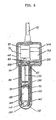
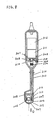
- Figs. 6 and 7 show an ultrasonic probe according to a third embodiment of this invention.
- the ultrasonic probe of Figs. 6 and 7 includes a casing 30l having a drive member accommodating portion 302, a narrow elongated portion 303, and a transducer element accommodating portion 304.
- a first enlarged end of the elongated portion 303 is connected to the drive member accommodating portion 302 by a connection member 305 fixed to the casing portions 302 and 303 via threads.
- a second enlarged end of the elongated portion 303 is connected to the transducer element accommodating portion 304.
- a motor 3ll and an encoder 3l2 are disposed within the casing portion 302.
- a drive shaft 3l0 is coaxially disposed within the casing portion 303.
- An ultrasonic transducer element 306 and a support 307 are disposed within the casing portion 304. At least part of the transducer element accommodating portion 304 is formed with an acoustic window.
- the ultrasonic probe When the ultrasonic probe is used, it is inserted into a coelom of a body in the direction D (see Fig. 6) corresponding to a longitudinal axis of the casing 30l.
- the transducer element 306 is attached to an outer surface of the support 307.
- the support 307 is rotatably connected to a frame 308 via a shaft 309 extending perpendicular to the longitudinal axis of the casing 30l or the insertion direction B.
- the shaft 309 is also perpendicular to the drive shaft 3l0.
- the support 307 and the transducer element 306 can rotate about the shaft 309.
- the frame 308 is supported by the casing portion 303.
- An end of the drive shaft 3l0 is rotatably supported by the frame 308.
- the other end of the drive shaft 3l0 is connected via a coupling 3l4 to an output shaft 3l3 of the motor 3ll so that the drive shaft 3l0 can be rotated by the motor 3ll.
- the motor 3ll is supported by the connection member 305.
- a power transmission mechanism connects the drive shaft 3l0 and the support 3l7 so that the support 3l7 rotates about the shaft 309 as the drive shaft 3l0 rotates.
- the power transmission mechanism changes the direction of a transmitted rotational force such that the axis of rotation of the support 3l7 is perpendicular to the axis of rotation of the drive shaft 3l0.
- the power transmission mechanism includes a combination of gears 3l5 and 3l6.
- the first gear 3l5 is fixedly mounted on the end of the drive shaft 3l0.
- the second gear 3l6 is attached to a side of the support 3l7.
- the gears 3l5 and 3l6 are in mesh.
- the motor 3ll is activated, the motor shaft 3l3 and the drive shaft 3l0 rotate together so that the support 307 and the transducer element 306 rotate together about the shaft 309.
- the elongated portion 303 and the transducer element accommodating portion 304 are filled with ultrasonic wave propagation liquid 3l7 composed of deaerated water, butanediol, or others.
- a sealing member 3l8 provided between the connection member 305 and the motor shaft 3l3 prevents leakage of the ultrasonic wave propagation liquid 3l7. Such a location of the sealing member 3l8 ensures the narrow design of a major part of the elongated casing portion 303.
- the elongated casing portion 303 includes an outer tube 3l9 and an inner tube 320 extending coaxially.
- the outer tube 3l9 is made of insulating material such as synthetic resin to prevent electric leakage from the ultrasonic probe to an examined body.
- the outer tube 320 is made of metal to increase the strength of the casing 30l.
- the motor 3ll is electrically connected via a cable (no reference character) to a main portion (not shown) of a medical ultrasonic diagnostic system so that the motor 3ll is controlled via an electric signal outputted from the main portion of the diagnostic system.
- the encoder 3l2 is associated with the motor shaft 3l3.
- the encoder 3l2 generates an electric signal or signals representing the angular position of the motor shaft 3l3 and the rotational speed of the motor shaft 3l3. Since the position of the transducer element 306 depends on the angular position of the motor shaft 3l3, the electric signal outputted by the encoder 3l2 also represents the position of the transducer element 306.
- the encoder 3l2 is electrically connected via the cable to the main portion of the diagnostic system so that the signal or signals are transmitted from the encoder 3l2 to the main portion of the diagnostic system.
- the transducer element 306 is electrically connected to the main portion of the diagnostic system so that electric signals are transmitted between the transducer element 306 and the main portion of the diagnostic system.
- the electrical connection between the transducer element 306 and the main portion of the diagnostic system includes the cable, and leads disposed in the casing 30l and extending between the transducer element 306 and the cable.
- the inner casing tube 320 has an axial hole 32l through which these leads extend.
- the metal inner tube 320 is electrically grounded to reduce the ingress of foreign noises into signals travelling along the leads. It should be noted that the leads are electrically insulated from the metal inner tube 320 by a suitable insulating arrangement.
- the transducer element accommodating portion 304 has an outside diameter of about 20 mm and a length of about 30 mm, and the elongated portion 303 has an outside diameter of about l0 mm and a length of about ll0 mm.
- the ultrasonic probe of Figs. 6 and 7 operates as follows. When the ultrasonic probe is used, it is inserted into a coelom of a body to be examined.
- the narrow design of the casing elongated portion 303 allows much eased pain to be inflicted on a patient during the insertion of the ultrasonic probe into the body of the patient.
- the motor 3ll is activated so that the drive shaft 3l0 rotates together with the motor shaft 3l3 and the coupling 3l4.
- the rotational force is transmitted from the drive shaft 3l0 to the support 307 via the gears 3l5 and 3l6, thereby rotating the support 307 and the transducer element 306.
- the transducer element 306 is activated so that a beam of ultrasonic wave pulses are emitted from the transducer element 306 into the examined body via the ultrasonic wave propagation liquid 3l7 and the acoustic window of the casing portion 304. Some of the emitted ultrasonic wave pulses are reflected by the examined body and return to the transducer element 306 via the acoustic window of the casing portion 304 and the ultrasonic wave propagation liquid 3l7. The transducer element 306 converts the reflected and returned ultrasonic wave pulses into a corresponding electric signal, which is transmitted to the main portion of the diagnostic system.
- the main portion of the diagnostic system processes this electric signal and thereby derives a display data signal corresponding to one scanning line in a known way.
- the data signal is indicated by a display such as a cathode-ray tube.
- the previously-mentioned operation to derive a diaplay data signal corresponding one scanning line is periodically reiterated while the transducer element 306 is rotated through a desired angle by the motor 3ll. In this way, the beam of ultrasonic wave pulses emitted from the transducer element 306 is scanned along a sector plane extending frontward of the ultrasonic probe with respect to the insertion direction D, so that a corresponding sector sectional image of the portion of the body extending frontward of the ultrasonic probe is obtained on the display.
- the main portion of the diagnostic system monitors the position of the transducer element 306 via the signal from the encoder 3l2 and controls the position of the transducer element 306 in accordance with the monitored information via the signal to the motor 3ll in conventional closed loop control. Furthermore, the main portion of the diagnostic system controls the speed of the motor 3ll in accordance with the speed signal from the encoder 3l2 to regulate the speed of rotation of the support 307 and the transducer element 306 at a constant value.
- Two or more ultrasonic transducer elements 306 may be arranged on the support 307.
- the support may be rotated in one direction only.
- the support 307 may be rotated through a given angular range in reciprocatory motion.
- the mechanical scanning arrangement may be replaced by an electronic scanning system in which the transducer element is of the linear array type, the faced array type, or the convex array type.
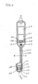
- Figs. 8 and 9 show an ultrasonic probe according to a fourth embodiment of this invention.
- the fourth embodiment is similar to the embodiment of Figs. 6 and 7 except for design changes described hereinafter.
- a condition sensor unit 322 disposed within the casing portion 302 generates an electric signal representing conditions related to operation of the motor 3ll.
- the condition sensor unit 322 is electrically connected to the main portion of the diagnostic system via the cable so that the electric signal is transmitted from the condition sensor unit 322 to the main portion of the diagnostic system.
- the condition sensor unit 322 includes a load section 323 and a temperature section 324 connected in series with a constant current supply (not shown).
- An electric line 325 connected between the condition sensor unit 322 and the main portion of the diagnostic system transmits the electric signal from the condition sensor unit 322 to the main portion of the diagnostic system.
- the load section 323 includes a variable resistor.
- the resistance of this variable resistor is predetermined as follows. After the assembly of the ultrasonic probe is completed, the motor 3ll is driven by a varying drive direct current at a given temperature, and the value of the drive current at which the speed of the motor 3ll equals a reference speed is detected. The resistance of the variable resistor is preset so as to correspond to this detected value of the drive current. Accordingly, the electric signal outputted via the electric line 325 represents this detected value of the drive current.
- the temperature section 324 includes a temperature responsive device or devices such as a diode and a thermistor.
- the reistance of the temperature section 324 varies with the temperature within the casing portion 302. Accordingly, the electric signal outputted via the electric line 325 represents the temperature within the casing portion 302.
- the main portion of the diagnostic system includes a phase-locked loop (PLL) circuit which basically serves to control the drive current of the motor 3ll in accordance with the signal from the encoder 3l2 so as to regulate the rotational speed of the support 307 and the transducer element 306 at a constant value.
- the signal outputted from the condition sensor unit 322 is used in the constant rotational speed control of the support 307 and the transducer element 306 to increase the reliability and the response characteristic of the control.
- the signal outputted from the condition sensor unit 322 is used to compensate variations in the load on the motor 3ll caused by dimensional errors of the parts and temperature changes. Accordingly, the PLL circuit can operate effectively and the yield during manufacture can be improved.
- condition sensor unit 322 may be located at other places.
- the condition sensor unit 322 may be embedded in the walls of the casing portion 302.
- One of the load section 323 and the temperature section 324 may be omitted from the condition sensor unit 322.
Landscapes
- Health & Medical Sciences (AREA)
- Life Sciences & Earth Sciences (AREA)
- Engineering & Computer Science (AREA)
- Physics & Mathematics (AREA)
- Surgery (AREA)
- Public Health (AREA)
- Radiology & Medical Imaging (AREA)
- Nuclear Medicine, Radiotherapy & Molecular Imaging (AREA)
- Biomedical Technology (AREA)
- Heart & Thoracic Surgery (AREA)
- Medical Informatics (AREA)
- Molecular Biology (AREA)
- Biophysics (AREA)
- Animal Behavior & Ethology (AREA)
- General Health & Medical Sciences (AREA)
- Pathology (AREA)
- Veterinary Medicine (AREA)
- Radar, Positioning & Navigation (AREA)
- Remote Sensing (AREA)
- Acoustics & Sound (AREA)
- Computer Networks & Wireless Communication (AREA)
- General Physics & Mathematics (AREA)
- Multimedia (AREA)
- Gynecology & Obstetrics (AREA)
- Ultra Sonic Daignosis Equipment (AREA)
- Investigating Or Analyzing Materials By The Use Of Ultrasonic Waves (AREA)
Priority Applications (1)
| Application Number | Priority Date | Filing Date | Title |
|---|---|---|---|
| EP91113305A EP0460711B1 (fr) | 1986-07-07 | 1987-07-06 | Sonde à ultrasons |
Applications Claiming Priority (6)
| Application Number | Priority Date | Filing Date | Title |
|---|---|---|---|
| JP104044/86U | 1986-07-07 | ||
| JP10404486U JPH065767Y2 (ja) | 1986-07-07 | 1986-07-07 | 機械走査式超音波探触子 |
| JP1986108465U JPH0639684Y2 (ja) | 1986-07-15 | 1986-07-15 | 体腔内超音波探触子 |
| JP165839/86 | 1986-07-15 | ||
| JP108465/86U | 1986-07-15 | ||
| JP61165839A JPH0698128B2 (ja) | 1986-07-15 | 1986-07-15 | 機械式走査型超音波探触子 |
Related Child Applications (1)
| Application Number | Title | Priority Date | Filing Date |
|---|---|---|---|
| EP91113305.6 Division-Into | 1991-08-08 |
Publications (2)
| Publication Number | Publication Date |
|---|---|
| EP0253268A1 true EP0253268A1 (fr) | 1988-01-20 |
| EP0253268B1 EP0253268B1 (fr) | 1992-12-30 |
Family
ID=27310138
Family Applications (2)
| Application Number | Title | Priority Date | Filing Date |
|---|---|---|---|
| EP87109728A Expired - Lifetime EP0253268B1 (fr) | 1986-07-07 | 1987-07-06 | Sonde à ultrasons |
| EP91113305A Expired - Lifetime EP0460711B1 (fr) | 1986-07-07 | 1987-07-06 | Sonde à ultrasons |
Family Applications After (1)
| Application Number | Title | Priority Date | Filing Date |
|---|---|---|---|
| EP91113305A Expired - Lifetime EP0460711B1 (fr) | 1986-07-07 | 1987-07-06 | Sonde à ultrasons |
Country Status (3)
| Country | Link |
|---|---|
| US (1) | US4895158A (fr) |
| EP (2) | EP0253268B1 (fr) |
| DE (2) | DE3783281T2 (fr) |
Cited By (7)
| Publication number | Priority date | Publication date | Assignee | Title |
|---|---|---|---|---|
| GB2212267A (en) * | 1987-11-11 | 1989-07-19 | Circulation Res Ltd | Three dimensional ultrasonic imaging apparatus |
| DE3929611A1 (de) * | 1988-09-12 | 1990-03-22 | Siemens Ag | Intracavitaere ultraschallsonde |
| EP0402410A1 (fr) * | 1988-03-02 | 1990-12-19 | Laboratory Equipment, Corp. | Systeme de therapie et de localisation par ultrasons |
| US5107844A (en) * | 1989-04-06 | 1992-04-28 | Olympus Optical Co., Ltd. | Ultrasonic observing apparatus |
| EP1576926A1 (fr) * | 2002-12-24 | 2005-09-21 | Matsushita Electric Industrial Co., Ltd. | Sonde ultrasonore |
| WO2009097613A1 (fr) * | 2008-02-01 | 2009-08-06 | Medicis Technologies Corporation | Tête de thérapie à utiliser avec un système d'ultrasons |
| CN112755414A (zh) * | 2021-01-11 | 2021-05-07 | 无锡太湖学院 | 一种抑瘤驻波超声换能器 |
Families Citing this family (27)
| Publication number | Priority date | Publication date | Assignee | Title |
|---|---|---|---|---|
| US5161537A (en) * | 1990-03-26 | 1992-11-10 | Matsushita Electric Industrial Co., Ltd. | Ultrasonic diagnostic system |
| ATE179015T1 (de) * | 1992-09-24 | 1999-04-15 | Siemens Ag | Intrakavitäre ultraschallsonde |
| US5379772A (en) * | 1993-09-14 | 1995-01-10 | Intelliwire, Inc. | Flexible elongate device having forward looking ultrasonic imaging |
| US5413107A (en) * | 1994-02-16 | 1995-05-09 | Tetrad Corporation | Ultrasonic probe having articulated structure and rotatable transducer head |
| JPH08254446A (ja) * | 1995-03-16 | 1996-10-01 | Fujitsu Ltd | 超音波印字方法,超音波印字装置及び音響レンズの成形方法 |
| US6315732B1 (en) * | 1999-07-20 | 2001-11-13 | Scimed Life Systems, Inc. | Imaging catheter and methods of use for ultrasound-guided ablation |
| JP2001149372A (ja) * | 1999-11-26 | 2001-06-05 | Matsushita Electric Ind Co Ltd | 超音波探触子 |
| US6709397B2 (en) * | 2001-10-16 | 2004-03-23 | Envisioneering, L.L.C. | Scanning probe |
| US8137279B2 (en) * | 2001-10-16 | 2012-03-20 | Envisioneering, Llc | Scanning probe |
| WO2004100796A1 (fr) * | 2003-05-19 | 2004-11-25 | Matsushita Electric Industrial Co., Ltd. | Sonde ultrasonore |
| BRPI0417907A (pt) * | 2003-12-30 | 2007-04-10 | Liposonix Inc | cabeçote para ultra-som, aplicador de energia, meio para manobrar o mesmo, e, método para distribuir energia de ultra-som a uma superfìcie do corpo |
| DE102004008370B4 (de) * | 2004-02-20 | 2006-06-01 | Siemens Ag | Katheter zur Durchführung und Überwachung von Rotablation |
| DE102004008368B4 (de) * | 2004-02-20 | 2006-05-24 | Siemens Ag | Katheter zur Durchführung und Überwachung von Rotablation |
| EP1945103B1 (fr) | 2005-11-12 | 2016-08-10 | Boston Scientific Limited | Systemes et procedes pour reduire le bruit dans un systeme de catheter d'imagerie |
| CN101662980B (zh) * | 2007-01-19 | 2013-02-27 | 桑尼布鲁克健康科学中心 | 用于成像探头的扫描机构 |
| US8460195B2 (en) * | 2007-01-19 | 2013-06-11 | Sunnybrook Health Sciences Centre | Scanning mechanisms for imaging probe |
| US8852112B2 (en) | 2007-06-28 | 2014-10-07 | W. L. Gore & Associates, Inc. | Catheter with deflectable imaging device and bendable electrical conductor |
| US8864675B2 (en) * | 2007-06-28 | 2014-10-21 | W. L. Gore & Associates, Inc. | Catheter |
| US8285362B2 (en) | 2007-06-28 | 2012-10-09 | W. L. Gore & Associates, Inc. | Catheter with deflectable imaging device |
| WO2009146458A2 (fr) * | 2008-05-30 | 2009-12-03 | Gore Enterprise Holdings, Inc. | Sonde de cathéter ultrasonore en temps réel |
| US8506490B2 (en) * | 2008-05-30 | 2013-08-13 | W.L. Gore & Associates, Inc. | Real time ultrasound probe |
| KR101068040B1 (ko) * | 2009-07-24 | 2011-09-28 | 경북대학교 산학협력단 | 3차원 초음파 스캐너 |
| KR101222848B1 (ko) * | 2009-10-21 | 2013-01-16 | 삼성메디슨 주식회사 | 초음파 진단장치의 프로브 및 그 제어방법 |
| CN104837412B (zh) * | 2012-10-12 | 2018-06-29 | 玛芬股份有限公司 | 用于三维体内超声用途的装置和方法 |
| KR20150090636A (ko) * | 2014-01-29 | 2015-08-06 | 삼성메디슨 주식회사 | 초음파 프로브 및 이를 포함한 초음파 진단장치 |
| US11317892B2 (en) * | 2015-08-12 | 2022-05-03 | Muffin Incorporated | Over-the-wire ultrasound system with torque-cable driven rotary transducer |
| KR20190056168A (ko) * | 2017-11-16 | 2019-05-24 | 삼성메디슨 주식회사 | 진동 감쇄 모터 조립체 및 이를 포함하는 초음파 프로브 |
Citations (4)
| Publication number | Priority date | Publication date | Assignee | Title |
|---|---|---|---|---|
| US3817089A (en) * | 1971-06-30 | 1974-06-18 | Interscience Res Inst | Rotating probe high data acquistion rate apparatus |
| US4282879A (en) * | 1978-02-23 | 1981-08-11 | Tokyo Shibaura Denki Kabushiki Kaisha | Ultrasonic diagnosing apparatus |
| EP0039045A1 (fr) * | 1980-04-28 | 1981-11-04 | Olympus Optical Co., Ltd. | Appareil à ultrason pour endoscope en vue d'un diagnostic |
| EP0065275A1 (fr) * | 1981-05-20 | 1982-11-24 | Olympus Optical Co., Ltd. | Dispositif de diagnostic ultrasonore |
Family Cites Families (12)
| Publication number | Priority date | Publication date | Assignee | Title |
|---|---|---|---|---|
| US2764148A (en) * | 1950-07-11 | 1956-09-25 | Sheldon Edward Emannel | Endoscope means for the internal examination of the human body |
| US3454923A (en) * | 1968-02-01 | 1969-07-08 | Honeywell Inc | Transducer control apparatus |
| JPS5383370A (en) * | 1976-12-29 | 1978-07-22 | Aloka Co Ltd | Tomographic video scanning system |
| US4271706A (en) * | 1978-05-03 | 1981-06-09 | Georgetown University | Ultrasonic scanner |
| US4375818A (en) * | 1979-03-12 | 1983-03-08 | Olympus Optical Company Ltd. | Ultrasonic diagnosis system assembled into endoscope |
| US4399703A (en) * | 1980-10-16 | 1983-08-23 | Dymax Corporation | Ultrasonic transducer and integral drive circuit therefor |
| JPS58152547A (ja) * | 1982-03-05 | 1983-09-10 | オリンパス光学工業株式会社 | 体腔内超音波診断装置 |
| US4417583A (en) * | 1982-03-31 | 1983-11-29 | Bechai Nabil R | Apparatus and method of internal examination of gastro intestinal tract and adjacent organs |
| JPS59131339A (ja) * | 1984-01-09 | 1984-07-28 | オリンパス光学工業株式会社 | 内視鏡超音波診断装置 |
| US4785819A (en) * | 1984-03-30 | 1988-11-22 | Technicare Corporation | Ultrasonic in-line sector probe |
| US4674515A (en) * | 1984-10-26 | 1987-06-23 | Olympus Optical Co., Ltd. | Ultrasonic endoscope |
| US4756313A (en) * | 1986-11-05 | 1988-07-12 | Advanced Diagnostic Medical Systems, Inc. | Ultrasonic probe |
-
1987
- 1987-07-06 DE DE8787109728T patent/DE3783281T2/de not_active Expired - Lifetime
- 1987-07-06 EP EP87109728A patent/EP0253268B1/fr not_active Expired - Lifetime
- 1987-07-06 EP EP91113305A patent/EP0460711B1/fr not_active Expired - Lifetime
- 1987-07-06 DE DE3751117T patent/DE3751117T2/de not_active Expired - Lifetime
-
1989
- 1989-01-24 US US07/300,216 patent/US4895158A/en not_active Expired - Lifetime
Patent Citations (4)
| Publication number | Priority date | Publication date | Assignee | Title |
|---|---|---|---|---|
| US3817089A (en) * | 1971-06-30 | 1974-06-18 | Interscience Res Inst | Rotating probe high data acquistion rate apparatus |
| US4282879A (en) * | 1978-02-23 | 1981-08-11 | Tokyo Shibaura Denki Kabushiki Kaisha | Ultrasonic diagnosing apparatus |
| EP0039045A1 (fr) * | 1980-04-28 | 1981-11-04 | Olympus Optical Co., Ltd. | Appareil à ultrason pour endoscope en vue d'un diagnostic |
| EP0065275A1 (fr) * | 1981-05-20 | 1982-11-24 | Olympus Optical Co., Ltd. | Dispositif de diagnostic ultrasonore |
Cited By (15)
| Publication number | Priority date | Publication date | Assignee | Title |
|---|---|---|---|---|
| GB2246632B (en) * | 1987-11-11 | 1992-07-15 | Intravascular Res Ltd | Method and apparatus for the examination and treatment of internal organs |
| GB2212267A (en) * | 1987-11-11 | 1989-07-19 | Circulation Res Ltd | Three dimensional ultrasonic imaging apparatus |
| US5081993A (en) * | 1987-11-11 | 1992-01-21 | Circulation Research Limited | Methods and apparatus for the examination and treatment of internal organs |
| GB2212267B (en) * | 1987-11-11 | 1992-07-29 | Circulation Res Ltd | Methods and apparatus for the examination and treatment of internal organs |
| EP0402410A1 (fr) * | 1988-03-02 | 1990-12-19 | Laboratory Equipment, Corp. | Systeme de therapie et de localisation par ultrasons |
| EP0402410A4 (en) * | 1988-03-02 | 1992-03-11 | Laboratory Equipment, Corp. | Ultrasound localization and therapy system |
| DE3929611A1 (de) * | 1988-09-12 | 1990-03-22 | Siemens Ag | Intracavitaere ultraschallsonde |
| US5107844A (en) * | 1989-04-06 | 1992-04-28 | Olympus Optical Co., Ltd. | Ultrasonic observing apparatus |
| EP1576926A1 (fr) * | 2002-12-24 | 2005-09-21 | Matsushita Electric Industrial Co., Ltd. | Sonde ultrasonore |
| EP1576926A4 (fr) * | 2002-12-24 | 2009-02-11 | Panasonic Corp | Sonde ultrasonore |
| US8083681B2 (en) | 2002-12-24 | 2011-12-27 | Panasonic Corporation | Ultrasonic probe |
| US8926533B2 (en) | 2003-12-30 | 2015-01-06 | Liposonix, Inc. | Therapy head for use with an ultrasound system |
| WO2009097613A1 (fr) * | 2008-02-01 | 2009-08-06 | Medicis Technologies Corporation | Tête de thérapie à utiliser avec un système d'ultrasons |
| CN101959556B (zh) * | 2008-02-01 | 2013-11-27 | 麦迪斯技术公司 | 配用于超声波系统的治疗头 |
| CN112755414A (zh) * | 2021-01-11 | 2021-05-07 | 无锡太湖学院 | 一种抑瘤驻波超声换能器 |
Also Published As
| Publication number | Publication date |
|---|---|
| DE3751117D1 (de) | 1995-04-06 |
| US4895158A (en) | 1990-01-23 |
| DE3783281T2 (de) | 1993-07-22 |
| EP0460711B1 (fr) | 1995-03-01 |
| EP0460711A3 (en) | 1992-01-08 |
| EP0253268B1 (fr) | 1992-12-30 |
| DE3783281D1 (de) | 1993-02-11 |
| EP0460711A2 (fr) | 1991-12-11 |
| DE3751117T2 (de) | 1995-07-20 |
Similar Documents
| Publication | Publication Date | Title |
|---|---|---|
| EP0253268A1 (fr) | Sonde à ultrasons | |
| EP0504480B1 (fr) | Appareil de diagnostic par ultrasons utilisant une sonde à balayage linéaire et angulaire | |
| US4374525A (en) | Ultrasonic diagnostic apparatus for endoscope | |
| US4977898A (en) | Miniaturized encapsulated ultrasonic transducer | |
| US4834102A (en) | Endoscope for transesophageal echocardiography | |
| US4567895A (en) | Fully wetted mechanical ultrasound scanhead | |
| US5199437A (en) | Ultrasonic imager | |
| US4732156A (en) | Ultrasonic endoscope | |
| US4936307A (en) | Ultrasonic observation system and an ultrasonic endoscope system | |
| US5740804A (en) | Multipanoramic ultrasonic probe | |
| US5544660A (en) | Acoustic imaging catheter and method of operation | |
| US5291893A (en) | Endo-luminal ultrasonic instrument and method for its use | |
| EP0037047A2 (fr) | Dispositif de balayage ultrasonore pour l'examen des viscères | |
| US4426886A (en) | Ultrasonic scanner | |
| US4773426A (en) | Ultrasonic mechanical sector scanning transducer probe assembly | |
| CN1688255A (zh) | 用于超声射束三维扫描的机构和系统 | |
| EP0429799B1 (fr) | Méthode d'imagerie à ultrasons et appareil | |
| EP0174167A2 (fr) | Transducteurs ultrasonores pour examen médical diagnostique | |
| JP2512469B2 (ja) | 超音波振動子駆動装置 | |
| JP3075291B2 (ja) | 超音波プローブ | |
| JP3490593B2 (ja) | 3次元走査用超音波探触子 | |
| JP3095817B2 (ja) | 超音波診断装置 | |
| JPH0223177B2 (fr) | ||
| JPH0630937A (ja) | 超音波診断装置 | |
| JP2000070268A (ja) | 超音波プローブ |
Legal Events
| Date | Code | Title | Description |
|---|---|---|---|
| PUAI | Public reference made under article 153(3) epc to a published international application that has entered the european phase |
Free format text: ORIGINAL CODE: 0009012 |
|
| 17P | Request for examination filed |
Effective date: 19870706 |
|
| AK | Designated contracting states |
Kind code of ref document: A1 Designated state(s): DE FR GB |
|
| 17Q | First examination report despatched |
Effective date: 19910131 |
|
| GRAA | (expected) grant |
Free format text: ORIGINAL CODE: 0009210 |
|
| AK | Designated contracting states |
Kind code of ref document: B1 Designated state(s): DE FR GB |
|
| XX | Miscellaneous (additional remarks) |
Free format text: TEILANMELDUNG 91113305.6 EINGEREICHT AM 06/07/87. |
|
| REF | Corresponds to: |
Ref document number: 3783281 Country of ref document: DE Date of ref document: 19930211 |
|
| ET | Fr: translation filed | ||
| PLBE | No opposition filed within time limit |
Free format text: ORIGINAL CODE: 0009261 |
|
| STAA | Information on the status of an ep patent application or granted ep patent |
Free format text: STATUS: NO OPPOSITION FILED WITHIN TIME LIMIT |
|
| 26N | No opposition filed | ||
| REG | Reference to a national code |
Ref country code: GB Ref legal event code: IF02 |
|
| PGFP | Annual fee paid to national office [announced via postgrant information from national office to epo] |
Ref country code: DE Payment date: 20060629 Year of fee payment: 20 |
|
| PGFP | Annual fee paid to national office [announced via postgrant information from national office to epo] |
Ref country code: GB Payment date: 20060705 Year of fee payment: 20 |
|
| PGFP | Annual fee paid to national office [announced via postgrant information from national office to epo] |
Ref country code: FR Payment date: 20060719 Year of fee payment: 20 |
|
| REG | Reference to a national code |
Ref country code: GB Ref legal event code: PE20 |
|
| PG25 | Lapsed in a contracting state [announced via postgrant information from national office to epo] |
Ref country code: GB Free format text: LAPSE BECAUSE OF EXPIRATION OF PROTECTION Effective date: 20070705 |