EP0253200A2 - Druckkopfverschiebung für Verschleissausgleich - Google Patents
Druckkopfverschiebung für Verschleissausgleich Download PDFInfo
- Publication number
- EP0253200A2 EP0253200A2 EP87109389A EP87109389A EP0253200A2 EP 0253200 A2 EP0253200 A2 EP 0253200A2 EP 87109389 A EP87109389 A EP 87109389A EP 87109389 A EP87109389 A EP 87109389A EP 0253200 A2 EP0253200 A2 EP 0253200A2
- Authority
- EP
- European Patent Office
- Prior art keywords
- line
- printing
- electrodes
- printed
- data
- Prior art date
- Legal status (The legal status is an assumption and is not a legal conclusion. Google has not performed a legal analysis and makes no representation as to the accuracy of the status listed.)
- Granted
Links
Images


Classifications
-
- B—PERFORMING OPERATIONS; TRANSPORTING
- B41—PRINTING; LINING MACHINES; TYPEWRITERS; STAMPS
- B41J—TYPEWRITERS; SELECTIVE PRINTING MECHANISMS, i.e. MECHANISMS PRINTING OTHERWISE THAN FROM A FORME; CORRECTION OF TYPOGRAPHICAL ERRORS
- B41J2/00—Typewriters or selective printing mechanisms characterised by the printing or marking process for which they are designed
- B41J2/315—Typewriters or selective printing mechanisms characterised by the printing or marking process for which they are designed characterised by selective application of heat to a heat sensitive printing or impression-transfer material
- B41J2/32—Typewriters or selective printing mechanisms characterised by the printing or marking process for which they are designed characterised by selective application of heat to a heat sensitive printing or impression-transfer material using thermal heads
- B41J2/325—Typewriters or selective printing mechanisms characterised by the printing or marking process for which they are designed characterised by selective application of heat to a heat sensitive printing or impression-transfer material using thermal heads by selective transfer of ink from ink carrier, e.g. from ink ribbon or sheet
-
- B—PERFORMING OPERATIONS; TRANSPORTING
- B41—PRINTING; LINING MACHINES; TYPEWRITERS; STAMPS
- B41J—TYPEWRITERS; SELECTIVE PRINTING MECHANISMS, i.e. MECHANISMS PRINTING OTHERWISE THAN FROM A FORME; CORRECTION OF TYPOGRAPHICAL ERRORS
- B41J2/00—Typewriters or selective printing mechanisms characterised by the printing or marking process for which they are designed
- B41J2/385—Typewriters or selective printing mechanisms characterised by the printing or marking process for which they are designed characterised by selective supply of electric current or selective application of magnetism to a printing or impression-transfer material
- B41J2/425—Typewriters or selective printing mechanisms characterised by the printing or marking process for which they are designed characterised by selective supply of electric current or selective application of magnetism to a printing or impression-transfer material for removing surface layer selectively from electro-sensitive material, e.g. metal coated paper
-
- G—PHYSICS
- G06—COMPUTING; CALCULATING OR COUNTING
- G06K—GRAPHICAL DATA READING; PRESENTATION OF DATA; RECORD CARRIERS; HANDLING RECORD CARRIERS
- G06K15/00—Arrangements for producing a permanent visual presentation of the output data, e.g. computer output printers
- G06K15/02—Arrangements for producing a permanent visual presentation of the output data, e.g. computer output printers using printers
- G06K15/10—Arrangements for producing a permanent visual presentation of the output data, e.g. computer output printers using printers by matrix printers
Definitions
- This invention relates to printing with a set of print elements which experience wear in relation to the extent of use of each print element.
- the print elements typically operate on one side of a ribbon to transfer ink or marking material to paper or the like in contact with the other side of the ribbon.
- Such print elements typically are arranged in at least one column, with each element individually selectable to cause formation of individual dots which, together with other dots from the elements, form a character image.
- the specific embodiment discussed is a thermal printer with 40 electrodes in a column on a printhead.
- the 40 elements cover substantially one line during normal paper feed, so that ideally a dot from the bottom element would just touch a dot from the top element of the next line.
- the print elements may be wires or other dot-forming impact elements.
- US-A-4,167,342 describes a plurality of separated groups of print elements and the selection between the groups to even wear.
- US-A-4,247,207 is to printing characters in a matrix of seven dots high using a print element nine dots high.
- the seven elements selected are specified by a bit in the code defining the character to be printed, depending upon the form of the character. Thus, where a descender is to be prominent, the lower seven elements are used.
- US-A-4,521,123 is to displacing a printhead vertically so as to sequentially print higher and lower parts of a character.
- This invention employs observing a line to be printed before it is printed and shifting in accordance with the conditions observed by such look-ahead.
- Look-ahead is broadly conventional in printers, but no such function is known which is used to shift a column of print elements.
- the preferred embodiment of this invention is in a resistive ribbon printing system having forty electrodes in a column.
- Such systems are known and are described in various respects in a number of patents and patent applications assigned to the assignee of this invention.
- the following two patent applications are illustrative of such printing systems with respect to this invention : EP-A-104,332 and EP-A-180,049.
- the printhead of the preferred embodiment is for resistive ribbon printing and has forty electrodes in a column. Information defining the shape of characters printed is stored in memory in association with information specifying whether the character employs the bottom and top regions of the forty electrodes.
- a data processor or other electronic logic examines a line to be printed prior to the printing of the line, and the paper being printed upon is positioned at the top, middle, or bottom of a line so as to print in a less-used region of the electrodes.
- This invention permits the use of printheads having the same number of electrodes as is used without regard to this invention. Yet, wear is distributed more effectively than had electrodes been added. If electrodes were added, the ribbon would either be made wider or shifting between the printhead and the ribbon would be required. Widening the ribbon necessitates larger and heavier ribbon-related structures and use of increased ribbon area for a given amount of printing. The alternative of moving the ribbon to the region of the printhead shifted to for printing requires special mechanisms for this purpose, which necessitate added expense and the potential of unreliability.
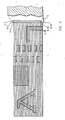
- Figure 1 is illustrative of a printing system employing this invention.
- the preferred system is a resistive ribbon printer 1 in which a ribbon 2 has a resistive outer layer against which a printhead 3 presses during printing.
- Printhead 3 supports 40 electrodes 5 in a column which covers vertically a line of printing on paper 7 held on platen 9 between printhead 3 and platen 9.
- the outer surface of ribbon 2 opposite printhead 3 carries a thermal ink which becomes flowable in response to heat created in ribbon 2 by electrical current driven into ribbon 2 by electrodes 5 of printhead 3.
- Printhead 3 is mounted on carrier 11 and moved across paper 7 parallel to platen 9, as suggested by the arrows on carrier 11.
- Electrodes 5 are driven or not driven with respect to the position of printhead 3 on paper 7 so as to define selected graphic images or characters.
- This printing system as just described is known and is described in a number of patent and patent applications assigned to the assignee of this invention, for example, as the printing system of the foregoing European applications EP-A-104,332 and EP-A-180,049.
- this printing system has a font memory 13, which preferably contains data as described in the foregoing application EP-A-104,332, but which additionally contains for each stored character a separate, two bit code specifying whether the specific character employs the top three electrodes in a column of forty electrodes, or the bottom three electrodes, or both the top three and the bottom three of the forty electrodes 5.
- the paper feed system 15 has the capability of feeding paper in increments of the spacing of three electrodes, which is 1/80 inch (approximately 0.03 cm) in the typical system where forty electrodes cover one line, which is 1/6 inch (approximately 0.42 cm). Such paper feed may be entirely conventional, as by a direct drive from a conventional stepper motor.
- the system is controlled by a central data processor 17, typically a microprocessor, but which may be special-purpose logic.
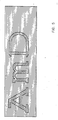
- Fig. 2 illustrate in some detail the forms of characters to be printed as they are positioned on a line of printing. Printing is made on a line as carrier 11 moves horizontally across paper 7 on platen 9, as is conventional. The print on Fig. 2 is shown in relation to the electrodes 5 and to horizontal lines along which the electrodes 5 sweep so that the inked areas made by each electrode is apparent. Electrodes 5 are denominated 5-1 through 5-40, with 5-1 being the top electrode, 5-2 being the next lower electrode, and the other electrodes being in sequence.
- the first character of the line shown in Fig. 2 is a capital A. This is generally centered in the print line and does not use electrodes 5-1, 5-2, 5-3, 5-38, 5-39, and 5-40 when printhead 3 is in the centered position as shown in Fig. 2.
- the next character is an upper one-half box, a common symbol used in certain graphics applications that extends to the very top of the line and therefore employs electrodes 5-1, 5-2, and 5-3 when printhead 3 is in the centered position, but does not employ electrodes 5-38, 5-39 and 5-40 when printhead 3 is in the centered position.
- the next character is a shading symbol of alternating black rectangles in a white background, which is also a known symbol used in graphics and which extends to the very top and bottom of the line.
- the shading symbol therefore employs both electrodes 5-1, 5-2, and 5-3 and electrodes 5-38, 5-39, and 5-40 when printhead 3 is in the centered position.
- the final character shown for illustration in Fig. 2 is an upper box corner, another common graphics symbol. This employs electrodes 5-38, 5-39, and 5-40 when the printhead 3 is in the centered position, but does not employ electrodes 5-1, 5-2, and 5-3 when printhead 3 is in the centered position.
- Other characters frequently using the region of the three top electrodes are the slash and accent marks of many European languages.
- the underline employs at least one of the bottom three electrodes.
- dots by which characters are formed separate from the electrodes 5 which form the dots.
- These dots are typically called picture elements or pels.
- the pels for each column may also be considered to be numbered from top to bottom.
- Each column in a line contains 40 pels, each of which will be printed dark or be left light because not printed.
- the electrodes 5 coincide with the pels since one electrode 5 is positioned above each pel.
- Fig. 3 illustrates a printed line with printhead 3 in the shifted-to-bottom-electrodes position where it has printed the line shown.
- Top line 20a indicates the top margin of the line being printed and bottom line 20b indicates the bottom margin of the line being printed. Shown in the line are characters lower case c and capital B in that order, followed by an upper one-half box.
- Electrodes 5 are positioned so that electrode 5-40 is located the height of three electrodes 5 above margin 20b, the bottom of the printed line. (Stated differently, electrodes 5-4 through 5-40 are positioned over pels 1 through 37.) This is possible because none of the characters in the line are formed by printing in the lower region.
- electrodes 5-1, 5-2, and 5-3 are above top margin 20a and therefore overlap the next higher line.
- electrodes 5-4 is driven when the data to be printed calls for the highest electrode in the current line to be driven and the lower electrodes 5 are similarly driven with data which relates the lower electrodes 5 to electrode 5-4 being the highest electrode.
- this bottom position electrode 5-40 receives data which would be received by electrode 5-37 when the electrodes are in the center position. (Stated differently, electrodes 5-4 through 5-40 receive data for pels 1 through 37 respectively, while electrodes 5-1 through 5-3 are not driven).
- Fig. 4 illustrates a printed line with printhead 3 in the shifted-to-top-electrodes position where it has printed the line shown.
- top line 20a indicates the top margin of the line being printed
- bottom line 20b indicates the bottom margin of the line being printed.
- Shown in the line are characters lower case c and capital B in that order, as well as lower case a underlined and a upper box corner.
- Electrodes 5 are positioned so that electrode 5-1 is the height of three electrodes 5 below line 20a, the top of the printed line. This is possible because none of the characters in the line are formed by printing in the upper region.
- electrodes 5-38, 5-39, and 5-40 are below line 20b and therefore overlap the next lower line.
- electrode 5-1 is driven when the data to be printed calls for the fourth highest electrode in a line to be driven and the lower electrodes 5 are similarly driven with data which relates the lower electrodes 5 to electrode 5-1 being the fourth highest electrode. Since the data is for forty electrodes, electrodes 5-38, 5-39, and 5-40 will not receive any data and therefore will not be driven when printhead 3 is in the shifted-to-top-electrodes position. (Stated differently, electrodes 5-1 through 5-37 receive data for pels 4 through 40 respectively, while electrodes 5-38 through 5-40 are not driven).
- Fig. 5 shows characters in styles having ornamented line endings and flourishes commonly called serifs. Typical type styles include areas, particularly at the bottom of letters and top of lower case letters, which are more heavily used. Additionally, serifs occur frequently enough to be a major source of differential wear of the printhead.
- the horizontal lines in Fig. 5 form stripes showing the areas printed by individual electrodes in this preferred embodiment.
- the capital A shown in Fig. 3 has a serif formed by a top, horizontal line extending from the very top of the letter to the left.
- the lower case m shown has bottom horizontal lines extending away from the body of the letter.
- the capital D shown has tapered left endings.
- Such serifs typically are among the smallest lines printed in any character set, and they typically require driving at least two contiguous electrodes 5 (equivalent to 1/120 inch or approximately 0.021 cm) and often three adjacent electrodes 5. By shifting the height of three electrodes 5 instead of some lesser amount, printing of serifs is generally shifted to completely different electrodes and wear is therefore better distributed.
- FIG. 6 A control system for specific implementation is illustrated in Fig. 6.
- Data defining characters to be printed is received in receive buffer 40, where it is observed by line-end logic 42, which compares the length of text received with a designated line length.
- Line-end logic 42 also recognizes a mandatory line ending code in the data as terminating a line.
- the character data is extracted from font memory 13, which, in addition to the standard function of defining the form of each character, also transmits to region-use logic 44 information as to whether each character employs the top-three-electrode region and the bottom-three electrode region of the centered printhead 3.
- Line end logic 42 signals region-use logic 44 at a line ending, and region-use logic 44 then determines the available shift positions of printhead 3.
- Selection of the printhead 3 shift position used is made by selection logic 46 based upon available position information from logic 44 and prior use of shift positions, with centered being the position selected if another position is not possible by the known information from the data.
- the three available shift positions are center, top (shift to top electrodes), and bottom (shift to bottom electrodes).
- the use of each position is monitored in counter 50, which is incremented to count each use of center; 52, which is incremented to count each use of bottom; and 54, which is incremented to count each use of top.
- Counters 50, 52, and 54 are preferably standard binary devices which employ eight bit positions and therefore have a full capacity of counting from zero to 255.
- Selection logic 46 selects the shift position based on the new shift position being one permitted by region-use logic 44 and being the least used of those permitted shift positions as shown by the lowest count in counters 50, 52, and 54. For example, region-use logic 44 may show that a line can be printed with printhead 3 in center or bottom. If counter 50 has a lower count than counter 52, selection logic 46 will select center and signal the printer (Fig. 1) accordingly.
- the maximum count of each counter 50, 52, and 54 is 255, and the counters 50, 52, and 54 are initiated at the same value, specifically 16.
- any counter 50, 52, and 54 reaches 255 the value in the counter 50, 52, and 54 having the smallest value is substracted from all of the counters 50, 52, and 54. Any resulting count below the initial value is reset to the initial value. (Two counts below the initial value are reset to the initial value in a counter which has the lower count and to the initial value plus one in a counter having a higher count). This retains generally the differential between the numbers in the counters to assure close approximation to even distribution of wear, while subtracting no more than the initial value assures that the counter 50, 52, and 54 are not presented with a negative result and therefore operated beyond their physical range.
- the initial line after turning on the machine is at center. Therefore, when the counts are even, shifting is by a set pattern of first to top if top available, then to bottom if top is not available, and then to center if top and bottom are not available.
- Line-end logic 42 also responds to buffer 56 being full or to a predetermined, long time period occuring, after which any content of buffer 56 will be printed (a standard time-out function). In these two conditions, further information to be printed in the line may follow, but is not available at the time of printing. These conditions are recognized by selection logic 46 to define printing as centered.
- initial data in buffer 56 is revised to define the shift position specified by selection logic 46.
- Characters are normally stored in buffer 56 as abbreviated, unique codes defining the character.
- the exact pel information defining the character form is produced by interrogating the font memory 13 and expanding that data by predetermined expansion formulas to define the exact character form with a logical one or logical zero representing each pel.
- buffer 56 is loaded with that exact pel information. These modes typically involve either modification of data of the font 13 or a bypassing of data in font 13. For example, for a superscript or subscript the font data may be used in a modified, compressed form to define the superscript or subscript. The character including the superscript in pel form is determined from the font using font information, and stored in buffer 56 in pel form. Similarly, the system may receive character information as an external input. Characters in pel form defined by such information are stored in pel form in buffer 56. In these specialized modes, buffer 56 is examined by region-use logic 44 for the existence of logical bits which define pels driven in the top three pels and the bottom three pels of a column.
- This information is equivalent to the font information of region-use in the font 13.
- the result of this information defines the available region in a line to be printed, which is transmitted to selection logic 46. Extracting the region-use information from data directly corresponding to the pels involved requires considerable data processing repetition and therefore may slow printing.
- determining the shift position rarely introduces noticeable delay in printer operation.
- paper feed 15 is activated to index platen 9 the distance of a full line height less the height of three electrodes 5 (to the bottom shift position), and carrier 11 is returned. (The full line high less three is 37 when the starting position is center, 40 when the starting position is bottom, and 34 when the starting position is top).
- platen 9 is signalled to index an additional distance equal to the height of three electrodes 5 upward for additional paper feed if the shift position is to center and is signalled to index the height of six electrodes 5 if the shift position is top.
- the overall system is fast enough that paper feed 15 operates continuously to move platen 9 is to actual printing position specified. In any event moving platen 9 backward is never required, which simplifies the functional requirements of paper feed 15.
- the center position is the normal one for printing as it is the position of a prior art printer of the king of this preferred embodiment.
- Such a prior art printer employed the 40 electrodes with printing in one position corresponding to the center position of this invention.
- Ribbon 1 is wide enough to be in contact with the 40 electrodes simultaneously, so that printing from any combination of the 40 electrodes may be done simultaneously.
- This invention requires no change of the positioning of ribbon 1 with respect to the 40 electrodes on printhead 3 since the shifting is with respect to the printhead and platen 9. No special mechanism is needed to shift ribbon 1 with respect to printhead 3 since no such shifting occurs in this embodiment. That avoids the need for a mechanism which would be both expensive and prone to error, since ribbon 3 would have to be both fed longitudinally and laterally.
- Wear at each electrode 5 is a function of actual use of the electrode 5.
- current is driven from an electrode 5 selected by the pel pattern being printed. That current causes some electrical discharge and possible ionization at the tip of the electrode, which is in contact with a resistive layer of ribbon 1.
- temperature is raised at the electrode 5 during the driving of current.
- wear is not established, increased wear as a function of actual frequency of current being driven during printing is experienced. Accordingly, by distributing that wear to other electrodes 5 which would otherwise be less frequently used, the entire set of electrodes 5 may be used for a greater amount of printing prior to one or more of the electrodes 5 being so deteriorated by wear that the printing is unsatisfactory.
- a typical increase of use for a system such as the preferred embodiment described is about 50 percent. It is apparent, of course, that in other systems, such as mechanical systems, wear is also a function of use and that this invention is similarly applicable to such systems.
- electrodes 5 preferably are each slightly wider than they would be to ideally just cover the height of one line, so that slightly excessive line indexing caused by normal operating variations will not result in a gap between print from the bottom electrode 5 of the higher line and the top electrode 5 of the next line below.
- the determination of use of the top and bottom regions may be by use of a separate memory storing line area used by each character rather than by storing that information directly with the form-of-character information.
- the system described is detrimental, such as when paper feed raises special problems when printing is near the very bottom of a page, the system is deactivated at such locations or modified to use only center and bottom positions at such locations by program control.
Landscapes
- Physics & Mathematics (AREA)
- Engineering & Computer Science (AREA)
- Mathematical Physics (AREA)
- General Engineering & Computer Science (AREA)
- General Physics & Mathematics (AREA)
- Theoretical Computer Science (AREA)
- Dot-Matrix Printers And Others (AREA)
- Electronic Switches (AREA)
- Character Spaces And Line Spaces In Printers (AREA)
Applications Claiming Priority (2)
| Application Number | Priority Date | Filing Date | Title |
|---|---|---|---|
| US06/885,356 US4740092A (en) | 1986-07-14 | 1986-07-14 | Printhead shifting for wear distribution |
| US885356 | 1986-07-14 |
Publications (3)
| Publication Number | Publication Date |
|---|---|
| EP0253200A2 true EP0253200A2 (de) | 1988-01-20 |
| EP0253200A3 EP0253200A3 (en) | 1988-11-09 |
| EP0253200B1 EP0253200B1 (de) | 1991-08-21 |
Family
ID=25386723
Family Applications (1)
| Application Number | Title | Priority Date | Filing Date |
|---|---|---|---|
| EP87109389A Expired - Fee Related EP0253200B1 (de) | 1986-07-14 | 1987-06-30 | Druckkopfverschiebung für Verschleissausgleich |
Country Status (4)
| Country | Link |
|---|---|
| US (1) | US4740092A (de) |
| EP (1) | EP0253200B1 (de) |
| JP (1) | JP2724352B2 (de) |
| DE (1) | DE3772288D1 (de) |
Cited By (5)
| Publication number | Priority date | Publication date | Assignee | Title |
|---|---|---|---|---|
| EP0529534A2 (de) * | 1991-08-23 | 1993-03-03 | Eastman Kodak Company | Gerät und Verfahren zum Halbton-Probedrucken |
| EP0567288A2 (de) * | 1992-04-21 | 1993-10-27 | Canon Kabushiki Kaisha | Tintenstrahlaufzeichnungssystem, das Bilderzerlegung verwendet |
| GB2302065A (en) * | 1995-06-14 | 1997-01-08 | Hewlett Packard Co | Inkjet printing with uniform wear of ink ejection elements and nozzles |
| WO2000068019A1 (en) * | 1999-05-10 | 2000-11-16 | Moore North America, Inc. | Enhancing printhead utilization |
| US6158835A (en) * | 1999-01-08 | 2000-12-12 | Hewlett-Packard Company | Nozzle usage balancing for ink-jet printers |
Families Citing this family (8)
| Publication number | Priority date | Publication date | Assignee | Title |
|---|---|---|---|---|
| US4929099A (en) * | 1988-01-19 | 1990-05-29 | Qume Corporation | Multi-line serial printer |
| US5044796A (en) * | 1989-01-19 | 1991-09-03 | Hewlett-Packard Company | Bidirectional printing method in accordance with vertical breaks |
| JPH04230590A (ja) * | 1990-10-31 | 1992-08-19 | Internatl Business Mach Corp <Ibm> | ドット・マトリクス・プリンタに対するプリントヘッドの寿命を増大させるための方法及び装置 |
| GB9410273D0 (en) * | 1994-05-20 | 1994-07-13 | Prestek Ltd | Printing apparatus |
| GB2289652A (en) * | 1994-05-26 | 1995-11-29 | Illinois Tool Works | Ink ribbon economy strategies for thermal printers. |
| GB9621475D0 (en) * | 1996-10-15 | 1996-12-04 | Itw Ltd | A method of operating a thermal printer |
| JP2003237140A (ja) * | 2002-02-14 | 2003-08-27 | Pfu Ltd | プリンタ装置及び光学式読取装置 |
| RU2516189C2 (ru) * | 2012-08-31 | 2014-05-20 | Общество с ограниченной ответственностью "Энкон-сервис" (ООО "Энкон-сервис") | Способ нанесения металлического покрытия на токопередающие поверхности разборных контактных соединений |
Citations (4)
| Publication number | Priority date | Publication date | Assignee | Title |
|---|---|---|---|---|
| US4033444A (en) * | 1976-01-20 | 1977-07-05 | Burroughs Corporation | System for extending the life of a pin printer using pin shifting |
| US4247207A (en) * | 1978-01-09 | 1981-01-27 | The Rank Organisation Limited | Matrix printer |
| EP0104332A2 (de) * | 1982-09-27 | 1984-04-04 | International Business Machines Corporation | Drucksystem mit Kompression grafischer Daten |
| EP0185999A2 (de) * | 1984-12-12 | 1986-07-02 | HONEYWELL BULL ITALIA S.p.A. | Punktmatrixseriendrucker |
Family Cites Families (10)
| Publication number | Priority date | Publication date | Assignee | Title |
|---|---|---|---|---|
| US4167342A (en) * | 1977-06-13 | 1979-09-11 | Dataproducts Corporation | Control system for matrix print head |
| JPS5824459A (ja) * | 1981-08-05 | 1983-02-14 | Tokyo Electric Co Ltd | サ−マルラベルプリンタ |
| DE3235676A1 (de) * | 1982-09-27 | 1984-03-29 | Siemens AG, 1000 Berlin und 8000 München | Verfahren und anordnung zum darstellen von zeichen |
| JPS59156783A (ja) * | 1983-02-25 | 1984-09-06 | Hitachi Ltd | シリアルドツトプリンタ |
| JPS59181747A (ja) * | 1983-03-31 | 1984-10-16 | Canon Inc | デ−タ伝送制御方式 |
| JPS6015169A (ja) * | 1983-07-06 | 1985-01-25 | Fujitsu Ltd | プリンタ |
| JPS60129266A (ja) * | 1983-12-15 | 1985-07-10 | Sharp Corp | ドツトプリンタにおけるライン印字方式 |
| JPS6192866A (ja) * | 1984-10-12 | 1986-05-10 | Fujitsu Ltd | ドツトプリンタの印刷制御方式 |
| US4575731A (en) * | 1984-10-30 | 1986-03-11 | International Business Machines Corporation | Electro resistive printhead drive level sensing and control |
| US4625216A (en) * | 1985-08-05 | 1986-11-25 | Ncr Canada Ltd. | Thermal printhead life extension technique |
-
1986
- 1986-07-14 US US06/885,356 patent/US4740092A/en not_active Expired - Lifetime
-
1987
- 1987-06-30 DE DE8787109389T patent/DE3772288D1/de not_active Expired - Fee Related
- 1987-06-30 EP EP87109389A patent/EP0253200B1/de not_active Expired - Fee Related
- 1987-07-14 JP JP62174063A patent/JP2724352B2/ja not_active Expired - Fee Related
Patent Citations (4)
| Publication number | Priority date | Publication date | Assignee | Title |
|---|---|---|---|---|
| US4033444A (en) * | 1976-01-20 | 1977-07-05 | Burroughs Corporation | System for extending the life of a pin printer using pin shifting |
| US4247207A (en) * | 1978-01-09 | 1981-01-27 | The Rank Organisation Limited | Matrix printer |
| EP0104332A2 (de) * | 1982-09-27 | 1984-04-04 | International Business Machines Corporation | Drucksystem mit Kompression grafischer Daten |
| EP0185999A2 (de) * | 1984-12-12 | 1986-07-02 | HONEYWELL BULL ITALIA S.p.A. | Punktmatrixseriendrucker |
Cited By (10)
| Publication number | Priority date | Publication date | Assignee | Title |
|---|---|---|---|---|
| EP0529534A2 (de) * | 1991-08-23 | 1993-03-03 | Eastman Kodak Company | Gerät und Verfahren zum Halbton-Probedrucken |
| EP0529534A3 (en) * | 1991-08-23 | 1993-07-14 | Eastman Kodak Company | Apparatus and method for printing half-tone proof images |
| EP0567288A2 (de) * | 1992-04-21 | 1993-10-27 | Canon Kabushiki Kaisha | Tintenstrahlaufzeichnungssystem, das Bilderzerlegung verwendet |
| EP0567288A3 (de) * | 1992-04-21 | 1994-03-16 | Canon Kk | |
| GB2302065A (en) * | 1995-06-14 | 1997-01-08 | Hewlett Packard Co | Inkjet printing with uniform wear of ink ejection elements and nozzles |
| GB2302065B (en) * | 1995-06-14 | 1998-06-17 | Hewlett Packard Co | Inkjet printing with uniform wear of ink ejection elements and nozzles |
| US6565190B1 (en) | 1995-06-14 | 2003-05-20 | Hewlett-Packard Company | Inkjet printing with uniform wear of ink ejection elements and nozzles |
| US6158835A (en) * | 1999-01-08 | 2000-12-12 | Hewlett-Packard Company | Nozzle usage balancing for ink-jet printers |
| WO2000068019A1 (en) * | 1999-05-10 | 2000-11-16 | Moore North America, Inc. | Enhancing printhead utilization |
| US6290326B1 (en) | 1999-05-10 | 2001-09-18 | Moore North America, Inc. | Enhancing printhead utilization |
Also Published As
| Publication number | Publication date |
|---|---|
| DE3772288D1 (de) | 1991-09-26 |
| JP2724352B2 (ja) | 1998-03-09 |
| US4740092A (en) | 1988-04-26 |
| EP0253200A3 (en) | 1988-11-09 |
| JPS6328659A (ja) | 1988-02-06 |
| EP0253200B1 (de) | 1991-08-21 |
Similar Documents
| Publication | Publication Date | Title |
|---|---|---|
| EP0220443B1 (de) | Verfahren zur Steuerung eines Bit-Bilddruckers | |
| US4740092A (en) | Printhead shifting for wear distribution | |
| US4323315A (en) | Electronic typewriter with display device | |
| CA1113194A (en) | Advertising copy composition and lay-out system | |
| CA1087744A (en) | Digital display composition system | |
| EP0575057A2 (de) | Bidirektionaler Tintenstrahldrucker | |
| EP0264265B1 (de) | Drucksystem zur Steuerung der Bewegungsgeschwindigkeit des Druckkopfes | |
| EP0513290B1 (de) | Vorrichtung zum herstellen von bedruckten etiketten | |
| US4929099A (en) | Multi-line serial printer | |
| EP0063939A2 (de) | Schreibanordnung | |
| EP0160318B1 (de) | Drucksystem für einen Punktmatrixdrucker | |
| US4704040A (en) | Memory device and printing system for dot printer | |
| KR890001751B1 (ko) | 프린터 | |
| US4721401A (en) | Printhead control | |
| US5319390A (en) | Thermal printer apparatus | |
| US4883377A (en) | Character pattern generator for dot matrix printer | |
| EP0112060B1 (de) | Anzeigeeinrichtung für mit einer Tastatur eingegebene Daten | |
| US4650348A (en) | Method of dot-printing underlines | |
| JPS6353951B2 (de) | ||
| US4952082A (en) | Text processing system for cyclically shifting format memory | |
| US4789949A (en) | Printer throughput | |
| US5897255A (en) | Speed fonts for matrix printers | |
| US4695172A (en) | Printer with display for double-width character | |
| EP0345084B1 (de) | Punktmatrixdrucker mit zwei Sätzen punktbildender Elemente | |
| US5238312A (en) | Impact printer with printing pressure setting |
Legal Events
| Date | Code | Title | Description |
|---|---|---|---|
| PUAI | Public reference made under article 153(3) epc to a published international application that has entered the european phase |
Free format text: ORIGINAL CODE: 0009012 |
|
| AK | Designated contracting states |
Kind code of ref document: A2 Designated state(s): DE FR GB IT |
|
| 17P | Request for examination filed |
Effective date: 19880530 |
|
| PUAL | Search report despatched |
Free format text: ORIGINAL CODE: 0009013 |
|
| AK | Designated contracting states |
Kind code of ref document: A3 Designated state(s): DE FR GB IT |
|
| RHK1 | Main classification (correction) |
Ipc: B41J 3/02 |
|
| 17Q | First examination report despatched |
Effective date: 19900521 |
|
| GRAA | (expected) grant |
Free format text: ORIGINAL CODE: 0009210 |
|
| AK | Designated contracting states |
Kind code of ref document: B1 Designated state(s): DE FR GB IT |
|
| REF | Corresponds to: |
Ref document number: 3772288 Country of ref document: DE Date of ref document: 19910926 |
|
| RAP2 | Party data changed (patent owner data changed or rights of a patent transferred) |
Owner name: LEXMARK INTERNATIONAL, INC. |
|
| ET | Fr: translation filed | ||
| ITF | It: translation for a ep patent filed |
Owner name: SOCIETA' ITALIANA BREVETTI S.P.A. |
|
| ITPR | It: changes in ownership of a european patent |
Owner name: PEGNO;J.P. MORGAN DELAWARE |
|
| REG | Reference to a national code |
Ref country code: GB Ref legal event code: 732 |
|
| PLBE | No opposition filed within time limit |
Free format text: ORIGINAL CODE: 0009261 |
|
| STAA | Information on the status of an ep patent application or granted ep patent |
Free format text: STATUS: NO OPPOSITION FILED WITHIN TIME LIMIT |
|
| 26N | No opposition filed | ||
| PGFP | Annual fee paid to national office [announced via postgrant information from national office to epo] |
Ref country code: FR Payment date: 20010531 Year of fee payment: 15 |
|
| PGFP | Annual fee paid to national office [announced via postgrant information from national office to epo] |
Ref country code: GB Payment date: 20010604 Year of fee payment: 15 Ref country code: DE Payment date: 20010604 Year of fee payment: 15 |
|
| REG | Reference to a national code |
Ref country code: GB Ref legal event code: IF02 |
|
| PG25 | Lapsed in a contracting state [announced via postgrant information from national office to epo] |
Ref country code: GB Free format text: LAPSE BECAUSE OF NON-PAYMENT OF DUE FEES Effective date: 20020630 |
|
| PG25 | Lapsed in a contracting state [announced via postgrant information from national office to epo] |
Ref country code: DE Free format text: LAPSE BECAUSE OF NON-PAYMENT OF DUE FEES Effective date: 20030101 |
|
| GBPC | Gb: european patent ceased through non-payment of renewal fee |
Effective date: 20020630 |
|
| PG25 | Lapsed in a contracting state [announced via postgrant information from national office to epo] |
Ref country code: FR Free format text: LAPSE BECAUSE OF NON-PAYMENT OF DUE FEES Effective date: 20030228 |
|
| REG | Reference to a national code |
Ref country code: FR Ref legal event code: ST |
|
| PG25 | Lapsed in a contracting state [announced via postgrant information from national office to epo] |
Ref country code: IT Free format text: LAPSE BECAUSE OF NON-PAYMENT OF DUE FEES Effective date: 20050630 |