EP0252895A2 - Method and apparatus for producing high resistant rails - Google Patents
Method and apparatus for producing high resistant rails Download PDFInfo
- Publication number
- EP0252895A2 EP0252895A2 EP87870094A EP87870094A EP0252895A2 EP 0252895 A2 EP0252895 A2 EP 0252895A2 EP 87870094 A EP87870094 A EP 87870094A EP 87870094 A EP87870094 A EP 87870094A EP 0252895 A2 EP0252895 A2 EP 0252895A2
- Authority
- EP
- European Patent Office
- Prior art keywords
- rail
- cooling
- water
- temperature
- core
- Prior art date
- Legal status (The legal status is an assumption and is not a legal conclusion. Google has not performed a legal analysis and makes no representation as to the accuracy of the status listed.)
- Granted
Links
Images

Classifications
-
- C—CHEMISTRY; METALLURGY
- C21—METALLURGY OF IRON
- C21D—MODIFYING THE PHYSICAL STRUCTURE OF FERROUS METALS; GENERAL DEVICES FOR HEAT TREATMENT OF FERROUS OR NON-FERROUS METALS OR ALLOYS; MAKING METAL MALLEABLE, e.g. BY DECARBURISATION OR TEMPERING
- C21D1/00—General methods or devices for heat treatment, e.g. annealing, hardening, quenching or tempering
- C21D1/18—Hardening; Quenching with or without subsequent tempering
- C21D1/19—Hardening; Quenching with or without subsequent tempering by interrupted quenching
-
- C—CHEMISTRY; METALLURGY
- C21—METALLURGY OF IRON
- C21D—MODIFYING THE PHYSICAL STRUCTURE OF FERROUS METALS; GENERAL DEVICES FOR HEAT TREATMENT OF FERROUS OR NON-FERROUS METALS OR ALLOYS; MAKING METAL MALLEABLE, e.g. BY DECARBURISATION OR TEMPERING
- C21D9/00—Heat treatment, e.g. annealing, hardening, quenching or tempering, adapted for particular articles; Furnaces therefor
- C21D9/04—Heat treatment, e.g. annealing, hardening, quenching or tempering, adapted for particular articles; Furnaces therefor for rails
Definitions
- the present invention relates to a method for manufacturing a high-resistance rail, as well as to a device for implementing this method.
- This process involves heat treatment of the rail as soon as it leaves the rolling mill, that is to say in the rolling hot.
- the rails are subjected to increasingly severe stresses which require ever higher levels of properties.
- the aforementioned strength properties are especially important in the bead of the rail, because it is this part, and in particular its upper zone, which is subjected to the highest stresses, in particular in terms of wear and shocks.
- the bead of the rail must be made of fine perlite free from proeutectoid ferrite and martensite and possibly containing a small percentage of bainite, and that it is also advisable for the hardness gradient in the bead be as low as possible.
- the steels used for the manufacture of high strength rails generally contain from 0.4% to 0.85% of carbon, from 0.4 to 1% of manganese and from 0.1% to 0.4% of silicon, the the rest being essentially iron.
- This process makes it possible to economically produce straight rails, having the desired properties, in particular a Brinell hardness of the order of 380, with steels having the composition mentioned above.
- alloying elements for example from 0.1% to 0.5% of chromium and up to 1% of silicon.
- the present invention provides a method for producing high strength rails, having a Brinell hardness of at least about 400 in the upper region of the bead, while avoiding the drawbacks mentioned above.
- the Applicant wishes to clarify what is meant, in practice, by the expression "immediately after leaving the rail of the rolling mill train". It is known that the rail leaving the rolling mill has irregularly shaped ends which must be cut; for this purpose, the rail is sent to a hot sawing station located between the actual outlet of the rolling mill and the controlled cooling installation. During this hot sawing operation, the rail inevitably undergoes a certain cooling in the air, but for an insufficient time for the temperature of the rail to drop to the point of causing an onset of allotropic transformation in the rail. It is after this cooling in the air that the controlled cooling which is the subject of the invention begins.
- the final cooling down to ambient temperature consists of a stay of the rail in the calm air during which the surface layer of the core undergoes tempering under the action of the heat which it draws , by conduction, of the interior parts of the soul. Also by conduction, these extract heat from the bead, cooled less intensely than the core. During this final cooling, the inner parts of the core transform into perlite.
- This additional cooling of the bead makes it possible to achieve the desired hardness of 400 Brinell while avoiding any formation of martensite in the bead.
- the cooling intensities will be expressed by the average density of heat flow characterizing these cooling. It is the quantity of heat (Joules) extracted from the rail per unit of time (seconds) and per unit of area (m2) of the surface subjected to cooling; it is expressed in MJ / s.m2 or MW / m2.
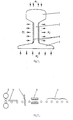
- Figure 1 shows, in cross section, a rail composed of a bead 1, a core 2 and a shoe 3.
- the constituent parts of the rail are subjected to respective cooling intensities ⁇ 1, ⁇ 2 and ⁇ 3, symbolized by arrows.
- the average heat flux density of the bead, ⁇ 1 provides cooling which gives rise to pearlitic transformation in the bead 1, without the formation of martensite.
- this average density of heat flow ⁇ 2 is much higher than ⁇ 1 and it gives rise to a real surface hardening of the core; it is formed, in the two faces of the core 2, surface layers 4 tempered, that is to say made of martensite and / or bainite.
- the average heat flux density ⁇ 3 in the shoe 3 is proportional to ⁇ 2 so as to avoid any difference in thermal deformation between the core and the shoe and thus to ensure the straightness of the rail during and after the treatment.
- the energetic cooling of the core 2 has the effect of extracting heat from the bead 1 and of contributing to the cooling of the latter. This effect is not, however, abrupt and it does not cause martensite formation in the bead. It nevertheless makes it possible to reduce the average density of heat flow ⁇ 1 and thus to soften the external cooling of the bead.
- the rail undergoes cooling in still air during which the heat remaining in the unhardened part of the core 2 ensures the income of the surface layers 4.
- the present invention also relates to a device for implementing the controlled cooling process which has just been described.
- FIG. 2 shows, in a highly simplified manner, such a device installed at the outlet of a rail train.
- the installation successively comprises a saw 7 for trimming or cutting the length of the rail, a device 8 for controlled cooling and equipment 9 for cooling in calm air.
- the rail runs continuously, on a roller conveyor, through the saw 7 and the cooling device 8, to the cooler 9.
- Figure 3 schematically shows the controlled rail cooling device, according to the invention, with the cooling water circuit. We have deliberately omitted to represent the equipment which is not essential for understanding the invention.
- the rail 5 seen here in cross section, are arranged cooling boxes equipped, in a manner known per se, with nozzles 10, 11, 12 ensuring respectively the cooling of the bead 1, the core 2 and the shoe 3 ( see figure 1) of the rail.
- the rail cooling water is then collected in a tank 13 at a constant level, from where it is returned by a pump 14 to a valve. mixer 15. This is connected to a source of make-up water, not shown.
- the water is then returned to the nozzles 10, 11, 12 through a pump 16 and a filter 17.
- the device also comprises an apparatus 18 for measuring the temperature of the water sent to the nozzles, and a regulator 19 which, depending on the water temperature, adjust the position of the mixing valve 15, in order to adjust the amount of makeup water to add to maintain the desired temperature.
- the temperature of the cooling water is advantageously between 40 ° C and 70 ° C.
- This modality associated with an appropriate adjustment of the nozzle flow, makes it possible to adjust the average density of heat flow in the different parts of the rail; in particular, it makes it possible to lower the value of ⁇ 1 to the level required to avoid the formation of martensite in the bead.
- the cooling water circulates in a closed circuit.
- a certain amount of water is added, at room temperature, through the mixing valve 15, so that the temperature of the water measured at 18 remains in the aforementioned range from 40 ° C to 70 ° C. Any excess water is discharged through an overflow provided in the tank 13.
- the water flow rate of the nozzles 11 is increased to the extent required to compensate for the decrease in ⁇ 2 associated with the use of water at relatively high temperature and thus obtain the cooling intensity necessary to ensure the intense surface cooling of the rail core.
- the method according to the invention makes it possible to continuously produce rails whose bead has a Brinell hardness of 400, without any alteration of the other mechanical or geometric properties mentioned in the introduction to the present application.
Abstract
Description
La présente invention concerne un procédé pour fabriquer un rail à haute résistance, ainsi qu'un dispositif pour la mise en oeuvre de ce procédé. Ce procédé comporte un traitement thermique du rail dès sa sortie du laminoir, c'est-à-dire dans la chaude de laminage.The present invention relates to a method for manufacturing a high-resistance rail, as well as to a device for implementing this method. This process involves heat treatment of the rail as soon as it leaves the rolling mill, that is to say in the rolling hot.
Par suite de la tendence actuelle à l'accroissement des charges et de la vitesse des convois ferroviaires, les rails sont soumis à des sollicitations de plus en plus sévères qui requièrent des niveaux de propriétés toujours plus élevés. A cet égard, il est particulièrement important que les rails présentent une rectitude aussi parfaite que possible ainsi que des niveaux élevés de résistance à l'usure, de résistance à la rupture fragile, de ductilité, de résistance à la fatigue et aux chocs, et de dureté. Enfin, ils doivent encore présenter une soudabilité satisfaisante.As a result of the current tendency towards increasing loads and the speed of railway convoys, the rails are subjected to increasingly severe stresses which require ever higher levels of properties. In this regard, it is particularly important that the rails have as perfect straightness as possible as well as high levels of wear resistance, brittle fracture strength, ductility, resistance to fatigue and impact, and hardness. Finally, they must still have satisfactory weldability.
D'un point de vue économique, il convient encore de maintenir leur prix à un niveau raisonnable, notamment en évitant ou en limitant le recours à des éléments d'alliages.From an economic point of view, their price should also be kept at a reasonable level, in particular by avoiding or limiting the use of alloying elements.
Les propriétés de résistance précitées sont spécialement importantes dans le bourrelet du rail, car c'est cette partie,et particulièrement sa zone supérieure, qui est soumise aux sollicitations les plus élevées, notamment en matière d'usure et de chocs.The aforementioned strength properties are especially important in the bead of the rail, because it is this part, and in particular its upper zone, which is subjected to the highest stresses, in particular in terms of wear and shocks.
On sait que pour présenter les propriétés requises, le bourrelet du rail doit être constitué de perlite fine exempte de ferrite proeutectoïde et de martensite et contenant éventuellement un faible pourcentage de bainite, et qu'il convient en outre que le gradient de dureté dans le bourrelet soit aussi faible que possible.It is known that in order to have the required properties, the bead of the rail must be made of fine perlite free from proeutectoid ferrite and martensite and possibly containing a small percentage of bainite, and that it is also advisable for the hardness gradient in the bead be as low as possible.
Les aciers utilisés pour la fabrication de rails à haute résistance contiennent généralement de 0,4 % à 0,85 % de carbone, de 0,4 à 1 % de manganèse et de 0,1 % à 0,4 % de silicium, le reste étant essentiellement du fer.The steels used for the manufacture of high strength rails generally contain from 0.4% to 0.85% of carbon, from 0.4 to 1% of manganese and from 0.1% to 0.4% of silicon, the the rest being essentially iron.
Dans une proposition antérieure qui fait l'objet notamment du brevet belge no 899.617, le présent Demandeur a décrit un procédé consistant à régler la longueur de la rampe de refroidissement, la vitesse de défilement du rail et la densité moyenne des flux calorifiques appliqués au bourrelet, à l'âme et au patin du rail de telle façon qu'il ne se forme de martensite en aucun point de la section du bourrelet et que moins de 60 % de la section du bourrelet aient subi la transformation allotropique austénite-perlite à la sortie de la rampe de refroidissement.In a prior proposal which is the subject in particular of the Belgian patent No. 899 617, the present Applicant has described a method of adjusting the length of the cooling gradient, speed of travel of the rail and the average density of the heat flux applied to bead, to the core and to the shoe of the rail in such a way that martensite is not formed at any point in the section of the bead and that less than 60% of the section of the bead has undergone the allotropic austenite-perlite transformation at the output of the cooling ramp.
Ce procédé permet de produire économiquement des rails bien droits, présentant les propriétés désirées, en particulier une dureté Brinell de l'ordre de 380, avec des aciers ayant la composition rappelée plus haut.This process makes it possible to economically produce straight rails, having the desired properties, in particular a Brinell hardness of the order of 380, with steels having the composition mentioned above.
Actuellement, ce niveau de dureté n'est cependant plus suffisant dans tous les cas et les utilisateurs imposent de plus en plus des duretés Brinell d'environ 400.Currently, this level of hardness is however no longer sufficient in all cases and users are increasingly imposing Brinell hardnesses of around 400.
Le procédé précité ne permet pas de répondre à cette nouvelle exigence, car il ne peut pas assurer un refroidissement suffisant pour atteindre la dureté requise sans former de la martensite.The above method does not meet this new requirement, because it can not provide sufficient cooling to achieve the required hardness without forming martensite.
On a alors cherché à augmenter la dureté du bourrelet en ajoutant à l'acier des éléments d'alliage, par exemple de 0,1 % à 0,5 % de chrome et jusqu'à 1 % de silicum.Attempts were then made to increase the hardness of the bead by adding alloying elements to the steel, for example from 0.1% to 0.5% of chromium and up to 1% of silicon.
Il est cependant apparu qu'une telle addition ne permettait pas d'atteindre le résultat désiré, c'est-à-dire une dureté Brinell 400 sans formation de martensite dans le bourrelet, en appliquant le procédé précité. Pour atteindre ce résultat, il faudrait en effet simultanément réduire fortement l'intensité du refroidissement jusqu'à un niveau incompatible avec le procédé et le dispositif du brevet belge précité et accroître dans des proportions importantes la durée du refroidissement. Celle-ci devrait par exemple être cinq fois plus longue, ce qui entraînerait soit une diminution correspondante de la vitesse du rail, soit une augmentation de la longueur de la rampe de refroidissement et par conséquent de l'encombrement de l'installation et des dépenses d'investissement nécessaires.However, it appeared that such an addition did not make it possible to achieve the desired result, that is to say a Brinell 400 hardness without formation of martensite in the bead, by applying the aforementioned process. To achieve this result, it would indeed be necessary to simultaneously greatly reduce the intensity of the cooling to a level incompatible with the process and the device of the aforementioned Belgian patent and to increase significantly the duration of cooling. This should for example be five times longer, which would either lead to a corresponding decrease in the speed of the rail, or an increase in the length of the cooling ramp and consequently in the space requirement of the installation and the expenses. investment required.
Par ailleurs, il n'est pas souhaitale de réduire fortement la vitesse du rail, car il en résulterait un séjour trop long de la queue du rail dans l'air et l'apparition d'un début de transformation allotropique avant le commencement du refroidissement contrôlé.Furthermore, it is not desirable to greatly reduce the speed of the rail, as this would result in the rail tail staying too long in the air and the appearance of an onset of allotropic transformation before the start of cooling. control.
La présente invention propose un procédé permettant de produire des rails à haute résistance, présentant une dureté Brinell d'environ 400 au moins dans la zone supérieure du bourrelet, tout en évitant les inconvénients rappelés plus haut.The present invention provides a method for producing high strength rails, having a Brinell hardness of at least about 400 in the upper region of the bead, while avoiding the drawbacks mentioned above.
Le procédé qui fait l'objet de la présente invention s'applique au rail, immédiatement après sa sortie du train de laminoir. Il est basé sur une constatation surprenante faite par le Demandeur, selon laquelle le refoidissement du bourrelet du rail est influencé dans une mesure appréciable par le régime de refroidissement de l'âme du rail.The process which is the subject of the present invention applies to the rail, immediately after it leaves the rolling mill train. It is based on a surprising observation made by the Applicant, according to which the cooling of the rail bead is influenced to an appreciable extent by the cooling regime of the rail core.
A cet égard, le Demandeur souhaite préciser ce que l'on entend, dans la pratique, par l'expression "immediatement après la sortie du rail du train de laminoir". On sait que le rail sortant du laminoir présente des extrémités de forme irrégulière qui doivent être coupées; à cet effet, le rail est envoyé à un poste de sciage à chaud situé entre la sortie proprement dite du laminoir et l'installation de refroidissement contrôlé. Pendant cette opération de sciage à chaud, le rail subit inévitablement un certain refroidissement dans l'air, mais pendant une durée insuffisante pour que la température du rail baisse au point de provoquer un début de transformation allotropique dans le rail. C'est après ce refroidissement dans l'air que commence le refroidissement contrôlé qui fait l'objet de l'invention.In this regard, the Applicant wishes to clarify what is meant, in practice, by the expression "immediately after leaving the rail of the rolling mill train". It is known that the rail leaving the rolling mill has irregularly shaped ends which must be cut; for this purpose, the rail is sent to a hot sawing station located between the actual outlet of the rolling mill and the controlled cooling installation. During this hot sawing operation, the rail inevitably undergoes a certain cooling in the air, but for an insufficient time for the temperature of the rail to drop to the point of causing an onset of allotropic transformation in the rail. It is after this cooling in the air that the controlled cooling which is the subject of the invention begins.
Au cours de ses recherches en vue d'accroître la dureté du bourrelet du rail, le Demandeur a constaté avec suprise qu'un refroidissement intensif de l'âme du rail, combiné au refroidissement propre du bourrelet, pouvait entraîner dans celui-ci l'apparitition d'une structure perlitique favorable ainsi que l'accroissement désiré de la dureté.During his research with a view to increasing the hardness of the rail bead, the Applicant was surprised to find that intensive cooling of the rail core, combined with the proper cooling of the bead, could lead to the appearance of a favorable pearlitic structure as well as the desired increase in hardness.
Dans ces conditions, le procédé pour fabriquer un rail à haute résistance, qui fait l'objet de la présente invention, dans lequel à sa sortie du laminoir à chaud, on soumet le rail en défilement continu à un refroidissement contrôlé, à partir d'une température au moins égale au point de transformation A₃ de l'acier, et on refroidit ensuite le rail jusqu'à la température ambiante, est essentiellement caractérisé en ce que le dit refroidissement contrôlé consiste simultanément :
- (a) à refroidir le bourrelet du rail jusqu'à une température qui n'est pas inférieure au point Ms de l'acier constituant le rail et à une vitesse inférieure à la vitesse critique de trempe dudit acier, de telle façon que le bourrelet acquière une structure perlitique fine;
- (b) à refroidir superficiellement l'âme du rail jusqu'à une température égale ou inférieure audit point Ms de l'acier et à une vitesse supérieure à la vitesse de refroidissement du bourrelet, de façon à obtenir dans l'âme du rail une couche superficielle constituée de martensite et/ou de bainite, ledit refroidissement superficiel de l'âme étant réglé de telle façon qu'à la fin de ce refroidissement, les parties intérieures de l'âme, non transformées en martensite et/ou en bainite, conservent une quantité de chaleur suffisante pour assurer, par conduction, un revenu de la couche superficielle transformée de l'âme au cours dudit refroidissement final;
- (c) et à refroidir le patin du rail avec une vitesse proportionnée à la vitesse de refroidissement de l'âme, afin d'éviter toute différence de déformation thermique entre l'âme et le patin du rail, de façon à garantir la rectitude du rail.
- (a) cooling the bead of the rail to a temperature which is not lower than the point Ms of the steel constituting the rail and at a speed lower than the critical quenching speed of said steel, so that the bead acquires a fine pearlitic structure;
- (b) superficially cooling the core of the rail to a temperature equal to or less than said point Ms of the steel and at a speed greater than the speed of cooling of the bead, so as to obtain in the core of the rail a surface layer consisting of martensite and / or bainite, said surface cooling of the core being adjusted so that at the end of this cooling, the internal parts of the core, not transformed into martensite and / or bainite, retain a sufficient amount of heat to ensure, by conduction, an income of the transformed surface layer of the core during said final cooling;
- (c) and to cool the shoe of the rail with a speed proportional to the speed of cooling of the core, in order to avoid any difference in thermal deformation between the core and the shoe of the rail, so as to guarantee the straightness of the rail.
Conformément à la présente invention, le refroidissement final jusqu'à la température ambiante consiste en un séjour du rail dans l'air calme au cours duquel la couche superficielle de l'âme subit un revenu sous l'action de la chaleur qu'elle soutire, par conduction, des parties intérieures de l'âme. Egalement par conduction, celles-ci extraient de la chaleur du bourrelet, refroidi moins intensément que l'âme. Pendant ce refroidissement final, les parties intérieures de l'âme se transforment en perlite.In accordance with the present invention, the final cooling down to ambient temperature consists of a stay of the rail in the calm air during which the surface layer of the core undergoes tempering under the action of the heat which it draws , by conduction, of the interior parts of the soul. Also by conduction, these extract heat from the bead, cooled less intensely than the core. During this final cooling, the inner parts of the core transform into perlite.
Ce refroidissement complémentaire du bourrelet, conformément au procédé de l'invention, permet d'atteindre la dureté désirée de 400 Brinell tout en évitant toute formation de martensite dans le bourrelet.This additional cooling of the bead, in accordance with the method of the invention, makes it possible to achieve the desired hardness of 400 Brinell while avoiding any formation of martensite in the bead.
Dans le cadre de la présente invention, les intensités de refroidissement seront exprimées par la densité moyenne de flux calorifique caractérisant ces refroidissements. Il s'agit de la quantité de chaleur (Joules) extraite du rail par unité de temps (seconde) et par unité d'aire (m²) de la surface soumise au refroidissement; elle s'exprime en MJ/s.m² ou MW/m².In the context of the present invention, the cooling intensities will be expressed by the average density of heat flow characterizing these cooling. It is the quantity of heat (Joules) extracted from the rail per unit of time (seconds) and per unit of area (m²) of the surface subjected to cooling; it is expressed in MJ / s.m² or MW / m².
La présente invention sera mieux comprise et d'autres particularités de celle-ci apparaîtront à la lecture de la description qui va suivre d'un mode de réalisation préféré, donné à titre d'exemple avec référence aux dessins annexés dans lesquels la
- figure 1 illustre, de façon schématique, les différents refroidissements appliqués simultanément au rail dans une zone de refroidissement contrôlé, avec indication des structures résultantes dans l'âme; la
- figure 2, fortement simplifiée, une installation de refroidissement contrôlé de rails à la sortie du laminoir à chaud; et la
- figure 3 représente schématiquement le circuit de l'eau de refroidissement dans un dispositif conforme à la présente invention.
- Figure 1 illustrates, schematically, the different cooling applied simultaneously to the rail in a controlled cooling zone, with indication of the resulting structures in the core; the
- Figure 2, greatly simplified, a controlled cooling installation of rails at the outlet of the hot rolling mill; and the
- Figure 3 schematically shows the cooling water circuit in a device according to the present invention.
La figure 1 représente, en coupe transversale, un rail composé d'un bourrelet 1, d'une âme 2 et d'un patin 3. Au cours du refroidissement contrôlé conforme à l'invention, les parties constitutives du rail sont soumises à des intensités de refroidissement respectives φ₁, φ₂ et φ₃, symbolisées par des flèches. La densité moyenne de flux calorifique du bourrelet, φ₁, assure un refroidissement qui donne lieu à la transformation perlitique dans le bourrelet 1, sans formation de martensite. Dans l'âme 2, cette densité moyenne de flux calorifique φ₂ est beaucoup plus élevée que φ₁ et elle donne lieu à une véritable trempe superficielle de l'âme; il se forme, dans les deux faces de l'âme 2, des couches superficielles 4 trempées, c'est-à-dire constituées de martensite et/ou de bainite. Enfin, la densité moyenne de flux calorifique φ₃ dans le patin 3 est proportionnée à φ₂ de façon à éviter toute différence de déformation thermique entre l'âme et le patin et à assurer ainsi la rectitude du rail pendant et après le traitement. Le refroidissement énergique de l'âme 2 a pour effet de soutirer de la chaleur du bourrelet 1 et de contribuer au refroidissement de ce dernier. Cet effet n'est cependant pas brutal et il n'entraîne pas de formation de martensite dans le bourrelet. Il permet néanmoins de réduire la densité moyenne de flux calorifique φ₁ et d'adoucir ainsi le refroidissement extérieur du bourrelet.Figure 1 shows, in cross section, a rail composed of a bead 1, a
Après ce refroidissement différentiel contrôlé, le rail subit un refroidissement dans l'air calme au cours duquel la chaleur restant dans la partie non trempée de l'âme 2 assure le revenu des couches superficielles 4.After this controlled differential cooling, the rail undergoes cooling in still air during which the heat remaining in the unhardened part of the
La présente invention porte également sur un dispositif pour la mise en oeuvre du procédé de refroidissement contrôlé qui vient d'être décrit.The present invention also relates to a device for implementing the controlled cooling process which has just been described.
La figure 2 montre, de façon fortement simplifiée, un tel dispositif installé à la sortie d'un train à rails. Dans le sens du déplacement du rail 5 sortant du laminoir 6, l'installation comprend successivement une scie 7 d'éboutage ou de mise à longueur du rail, un dispositif 8 de refroidissement contrôlé et un équipement 9 de refroidissement dans l'air calme. De façon connue en soi, le rail circule en continu, sur un convoyeur à rouleaux, à travers la scie 7 et le dispositif de refroidissement 8, jusqu'au refroidissoir 9.FIG. 2 shows, in a highly simplified manner, such a device installed at the outlet of a rail train. In the direction of movement of the
La figure 3 représente schématiquement le dispositif de refroidissement contrôlé du rail, conforme à l'invention, avec le circuit de l'eau de refroidissement. On a volontairement omis de représenter les équipements qui ne sont pas essentiels pour la compréhension de l'invention.Figure 3 schematically shows the controlled rail cooling device, according to the invention, with the cooling water circuit. We have deliberately omitted to represent the equipment which is not essential for understanding the invention.
Autour du rail 5, vu ici en coupe transversale, sont disposées des boîtes de refroidissement équipées, de façon connue en soi, de gicleurs 10, 11, 12 assurant respectivement le refroidissement du bourrelet 1, de l'âme 2 et du patin 3 (voir figure 1) du rail. L'eau de refroidissement du rail est ensuite recueillie dans une cuve 13 à niveau constant, d'où elle est renvoyée par une pompe 14 vers une vanne mélangeuse 15. Celle-ci est raccordée à une source d'eau d'appoint non représentée. L'eau est ensuite renvoyée vers les gicleurs 10, 11, 12 à travers une pompe 16 et un filtre 17. Le dispositif comprend encore un appareil 18 de mesure de la température de l'eau envoyée aux gicleurs, et un régulaleur 19 qui, en fonction de la température de l'eau, règle la position de la vanne mélangeuse 15, afin d'ajuster la quantité d'eau d'appoint à ajouter pour maintenir la température désirée.Around the
Dans la figure 3, les canalisations d'eau sont représentées en traits pleins et les conducteurs électriques sont représentés en traits interrompus.In Figure 3, the water pipes are shown in solid lines and the electrical conductors are shown in broken lines.
Selon l'invention, la température de l'eau de refroidissement est avantageusement comprise entre 40°C et 70°C.According to the invention, the temperature of the cooling water is advantageously between 40 ° C and 70 ° C.
Cette modalité, associée à un réglage approprié du débit des gicleurs, permet d'ajuster la densité moyenne de flux calorifique dans les différentes parties du rail; elle permet en particulier d'abaisser la valeur de φ₁ au niveau requis pour éviter la formation de martensite dans le bourrelet.This modality, associated with an appropriate adjustment of the nozzle flow, makes it possible to adjust the average density of heat flow in the different parts of the rail; in particular, it makes it possible to lower the value of φ₁ to the level required to avoid the formation of martensite in the bead.
Selon l'invention, l'eau de refroidissement circule en circuit fermé. Lorsque cela est nécessaire, on ajoute une certaine quantité d'eau, à la température ambiante, par la vanne mélangeuse 15,afin que la température de l'eau mesurée en 18 reste dans la gamme précitée de 40°C à 70°C. L'excès d'eau éventuel est évacué par un trop-plein prévu dans la cuve 13.According to the invention, the cooling water circulates in a closed circuit. When necessary, a certain amount of water is added, at room temperature, through the mixing
Egalement selon l'invention, on augmente le débit d'eau des gicleurs 11 dans la mesure requise pour compenser la diminution de φ₂ liée à l'utilisation d'eau à température relativement élevée et ainsi obtenir l'intensité de refroidissement nécessaire pour assurer le refroidissement superficiel intense de l'âme du rail.Also according to the invention, the water flow rate of the
Le procédé conforme à l'invention permet de produire en continue des rails dont le bourrelet présente une dureté Brinell de 400, sans aucune altération des autres propriétés mécaniques ou géométriques mentionnées dans l'introduction de la présente demande.The method according to the invention makes it possible to continuously produce rails whose bead has a Brinell hardness of 400, without any alteration of the other mechanical or geometric properties mentioned in the introduction to the present application.
Claims (9)
- des moyens de projection d'eau (10, 11, 12) disposés autour du rail (5);
- une cuve (13) à niveau constant, destinée à recueillir l'eau provenant des moyens de projection (10, 11, 12);
- des moyens (14 ;16) pour prélever l'eau de la cuve (13) et la faire circuler vers les moyens de projection (10, 11, 12);
- des moyens (15) pour ajouter de l'eau d'appoint à l'eau provenant de la cuve (13);
- un système de régulation de la température de l'eau de refroidissement, comprenant un appareil de mesure (18) de la température de l'eau avant lesdits moyens de projection et un régulateur (19) raccordé d'une part à l'appareil de mesure de la température (18) et d'autre part aux moyens (15) d'addition d'eau d'appoint.6. Device for manufacturing a high-resistance rail by the process which is the subject of claim 5, characterized in that it comprises:
- water spraying means (10, 11, 12) arranged around the rail (5);
- a tank (13) at constant level, intended to collect the water coming from the projection means (10, 11, 12);
- Means (14; 16) for taking water from the tank (13) and circulating it towards the projection means (10, 11, 12);
- Means (15) for adding make-up water to the water coming from the tank (13);
- a system for regulating the temperature of the cooling water, comprising a device for measuring (18) the temperature of the water before said projection means and a regulator (19) connected on the one hand to the device for measuring the temperature (18) and on the other hand to the means (15) for adding make-up water.
Priority Applications (1)
| Application Number | Priority Date | Filing Date | Title |
|---|---|---|---|
| AT87870094T ATE81676T1 (en) | 1986-07-10 | 1987-07-07 | METHOD AND DEVICE FOR MANUFACTURING HIGH STRENGTH RAILS. |
Applications Claiming Priority (2)
| Application Number | Priority Date | Filing Date | Title |
|---|---|---|---|
| LU86510 | 1986-07-10 | ||
| LU86510A LU86510A1 (en) | 1986-07-10 | 1986-07-10 | METHOD AND DEVICE FOR MANUFACTURING A HIGH RESISTANCE RAIL |
Publications (3)
| Publication Number | Publication Date |
|---|---|
| EP0252895A2 true EP0252895A2 (en) | 1988-01-13 |
| EP0252895A3 EP0252895A3 (en) | 1990-07-18 |
| EP0252895B1 EP0252895B1 (en) | 1992-10-21 |
Family
ID=19730736
Family Applications (1)
| Application Number | Title | Priority Date | Filing Date |
|---|---|---|---|
| EP87870094A Expired - Lifetime EP0252895B1 (en) | 1986-07-10 | 1987-07-07 | Method and apparatus for producing high resistant rails |
Country Status (7)
| Country | Link |
|---|---|
| US (1) | US4810311A (en) |
| EP (1) | EP0252895B1 (en) |
| JP (1) | JP2716127B2 (en) |
| AT (1) | ATE81676T1 (en) |
| CA (1) | CA1307723C (en) |
| DE (1) | DE3782280D1 (en) |
| LU (1) | LU86510A1 (en) |
Families Citing this family (9)
| Publication number | Priority date | Publication date | Assignee | Title |
|---|---|---|---|---|
| US5000798A (en) * | 1989-11-07 | 1991-03-19 | The Algoma Steel Corporation, Limited | Method for shape control of rail during accelerated cooling |
| EP0462783B1 (en) * | 1990-06-21 | 1995-09-27 | Nippon Steel Corporation | Process and apparatus for producing thin-webbed H-beam steel |
| US5259229A (en) * | 1990-06-21 | 1993-11-09 | Nippon Steel Corporation | Apparatus for cooling thin-webbed H-beam steel |
| US5306365A (en) * | 1992-11-19 | 1994-04-26 | Aluminum Company Of America | Apparatus and method for tapered heating of metal billet |
| US5419792A (en) * | 1994-07-25 | 1995-05-30 | General Electric Company | Method and apparatus for cooling a workpiece |
| US6174389B1 (en) | 1999-08-17 | 2001-01-16 | Caterpillar Inc. | Fixture and method for selectively quenching a predetermined area of a workpiece |
| US6394793B1 (en) | 2001-01-13 | 2002-05-28 | Ladish Company, Incorporated | Method and apparatus of cooling heat-treated work pieces |
| US20030098106A1 (en) * | 2001-11-29 | 2003-05-29 | United Technologies Corporation | Method and apparatus for heat treating material |
| US9840747B2 (en) | 2013-02-20 | 2017-12-12 | Rolls-Royce Corporation | Wall member useful in quenching |
Citations (7)
| Publication number | Priority date | Publication date | Assignee | Title |
|---|---|---|---|---|
| EP0098492A2 (en) * | 1982-07-06 | 1984-01-18 | The Algoma Steel Corporation, Limited | Method for the production of railway rails by accelerated cooling in line with the production rolling mill |
| EP0108436A1 (en) * | 1982-10-11 | 1984-05-16 | CENTRE DE RECHERCHES METALLURGIQUES CENTRUM VOOR RESEARCH IN DE METALLURGIE Association sans but lucratif | Rail making process and rails so produced |
| EP0136613A2 (en) * | 1983-10-04 | 1985-04-10 | Krupp Stahl AG | Rail having a high wear resistance in the head and a high resistance to rupture in the base |
| EP0161236A2 (en) * | 1984-05-09 | 1985-11-13 | CENTRE DE RECHERCHES METALLURGIQUES CENTRUM VOOR RESEARCH IN DE METALLURGIE Association sans but lucratif | Apparatus for manufacturing rails |
| JPS6299438A (en) * | 1985-10-24 | 1987-05-08 | Nippon Kokan Kk <Nkk> | Wear-resistant high-efficiency rail having instable fracture propagation stopping capacity |
| EP0186373B1 (en) * | 1984-12-24 | 1990-09-12 | Nippon Steel Corporation | Method of and apparatus for heat treating rails |
| JPH06299438A (en) * | 1993-02-26 | 1994-10-25 | Sulzer Rueti Ag | Inserting apparatus for loom wherein opening for warp is arranged in series |
Family Cites Families (7)
| Publication number | Priority date | Publication date | Assignee | Title |
|---|---|---|---|---|
| NL6715168A (en) * | 1967-08-30 | 1969-03-04 | ||
| US4203783A (en) * | 1977-09-19 | 1980-05-20 | Centre De Recherches Metallurgiques | Process for improving the quality of steel sections |
| JPS5547322A (en) * | 1978-09-30 | 1980-04-03 | Nippon Kokan Kk <Nkk> | Heat treating method for rail |
| JPS5832219A (en) * | 1981-08-19 | 1983-02-25 | Matsushita Electric Ind Co Ltd | Step-up type magnetic head |
| US4486248A (en) * | 1982-08-05 | 1984-12-04 | The Algoma Steel Corporation Limited | Method for the production of improved railway rails by accelerated cooling in line with the production rolling mill |
| JPS59169337U (en) * | 1983-04-25 | 1984-11-13 | 日本鋼管株式会社 | Steel cooling floor |
| DE3446794C1 (en) * | 1984-12-21 | 1986-01-02 | BWG Butzbacher Weichenbau GmbH, 6308 Butzbach | Process for the heat treatment of pearlitic rail steel |
-
1986
- 1986-07-10 LU LU86510A patent/LU86510A1/en unknown
-
1987
- 1987-07-07 DE DE8787870094T patent/DE3782280D1/en not_active Expired - Lifetime
- 1987-07-07 AT AT87870094T patent/ATE81676T1/en active
- 1987-07-07 EP EP87870094A patent/EP0252895B1/en not_active Expired - Lifetime
- 1987-07-09 US US07/071,689 patent/US4810311A/en not_active Expired - Lifetime
- 1987-07-09 CA CA000541732A patent/CA1307723C/en not_active Expired - Lifetime
- 1987-07-10 JP JP62172713A patent/JP2716127B2/en not_active Expired - Lifetime
Patent Citations (7)
| Publication number | Priority date | Publication date | Assignee | Title |
|---|---|---|---|---|
| EP0098492A2 (en) * | 1982-07-06 | 1984-01-18 | The Algoma Steel Corporation, Limited | Method for the production of railway rails by accelerated cooling in line with the production rolling mill |
| EP0108436A1 (en) * | 1982-10-11 | 1984-05-16 | CENTRE DE RECHERCHES METALLURGIQUES CENTRUM VOOR RESEARCH IN DE METALLURGIE Association sans but lucratif | Rail making process and rails so produced |
| EP0136613A2 (en) * | 1983-10-04 | 1985-04-10 | Krupp Stahl AG | Rail having a high wear resistance in the head and a high resistance to rupture in the base |
| EP0161236A2 (en) * | 1984-05-09 | 1985-11-13 | CENTRE DE RECHERCHES METALLURGIQUES CENTRUM VOOR RESEARCH IN DE METALLURGIE Association sans but lucratif | Apparatus for manufacturing rails |
| EP0186373B1 (en) * | 1984-12-24 | 1990-09-12 | Nippon Steel Corporation | Method of and apparatus for heat treating rails |
| JPS6299438A (en) * | 1985-10-24 | 1987-05-08 | Nippon Kokan Kk <Nkk> | Wear-resistant high-efficiency rail having instable fracture propagation stopping capacity |
| JPH06299438A (en) * | 1993-02-26 | 1994-10-25 | Sulzer Rueti Ag | Inserting apparatus for loom wherein opening for warp is arranged in series |
Non-Patent Citations (2)
| Title |
|---|
| PATENT ABSTRACTS OF JAPAN vol. 11, no. 315 (C-451)(2762) 14 octobre 1987; & JP-A-6299438 NIPPON KOKAN) 08.05.1987; & US-A-47 67475 * |
| PATENT ABSTRACTS OF JAPAN, vol. 11, no. 315 (C-451)(2762) 14 octobre 1987; & JP-A-62 099 438 (Nippon Kokan) 08.05.1987 * |
Also Published As
| Publication number | Publication date |
|---|---|
| DE3782280D1 (en) | 1992-11-26 |
| LU86510A1 (en) | 1988-02-02 |
| CA1307723C (en) | 1992-09-22 |
| US4810311A (en) | 1989-03-07 |
| ATE81676T1 (en) | 1992-11-15 |
| JP2716127B2 (en) | 1998-02-18 |
| EP0252895B1 (en) | 1992-10-21 |
| JPS6328824A (en) | 1988-02-06 |
| EP0252895A3 (en) | 1990-07-18 |
Similar Documents
| Publication | Publication Date | Title |
|---|---|---|
| EP0252895B1 (en) | Method and apparatus for producing high resistant rails | |
| EP0014655A1 (en) | Process for the manufacture of grinding members of an iron alloy | |
| US5879480A (en) | Process for imparting residual compressive stresses to steel machine components | |
| FR2738843A1 (en) | PROCESS FOR THERMALLY TREATING A STEEL RAIL | |
| FR2472022A1 (en) | PROCESS FOR THE PRODUCTION OF A TWO PHASE LAMINATED STEEL SHEET WHICH IS FORMED BY RAPID COOLING AFTER A CONTINUOUS NOISE | |
| LU85885A1 (en) | IMPROVED METHOD AND DEVICE FOR MANUFACTURING RAILS | |
| FR2659353A1 (en) | PROCESS FOR MANUFACTURING MECHANICAL PARTS, AND MECHANICAL PARTS OBTAINED BY THIS PROCESS. | |
| EP1844169B1 (en) | Gas quenching cell for steel parts | |
| LU80656A1 (en) | TREATMENT AND STRUCTURE OF A WELL BASED ON NON-FERROUS METAL | |
| JP2003136629A (en) | Multilayered material and method for manufacturing multilayered material | |
| EP0169827B1 (en) | Method for producing high-carbon steel wire rod | |
| LU88458A1 (en) | Method for modifying the section of a railroad and rail raul thus obtained | |
| EP0124501A1 (en) | Method of improving the quality of steel sections | |
| EP0132249B1 (en) | Process and device to produce concrete reinforcement bars on a high speed wire mill | |
| FR2488279A1 (en) | Controlled quenching of hot rolled steel rods - to give fine pearlitic-ferritic, lower bainitic or martensitic structure | |
| WO1996010095A1 (en) | Method for making rails | |
| FR2488532A1 (en) | METHOD OF RULE-NARROW NUTS ROLLING FOR SOFT STEEL REINFORCED SOFT BANDS | |
| EP1266041A1 (en) | Method for making a multiphase hot-rolled steel strip | |
| RU2087549C1 (en) | Method of heat treatment of products | |
| FR2488278A1 (en) | Spheroidisation annealing steel to improve cold formability - preceded by quenching from rolling temp. to reduce annealing time | |
| EP0220979B1 (en) | Process for the heat treatment of an article made of a uranium alloy | |
| FR2473062A1 (en) | Cooling of long prods, esp. steel rods for reinforcing concrete - which are briefly water quenched on leaving hot rolling mill to increase their mechanical strength | |
| FR2518080A1 (en) | METHOD FOR THE THERMALLY PRECONTROLLING OF GLASSES | |
| BE836408A (en) | PROCESS FOR THE MANUFACTURE OF STEEL ROUND | |
| LU85280A1 (en) | Improved quality low carbon steel products - obtd. by controlled surface cooling |
Legal Events
| Date | Code | Title | Description |
|---|---|---|---|
| PUAI | Public reference made under article 153(3) epc to a published international application that has entered the european phase |
Free format text: ORIGINAL CODE: 0009012 |
|
| AK | Designated contracting states |
Kind code of ref document: A2 Designated state(s): AT BE DE ES FR GB IT |
|
| PUAL | Search report despatched |
Free format text: ORIGINAL CODE: 0009013 |
|
| AK | Designated contracting states |
Kind code of ref document: A3 Designated state(s): AT BE DE ES FR GB IT |
|
| 17P | Request for examination filed |
Effective date: 19901130 |
|
| 17Q | First examination report despatched |
Effective date: 19911024 |
|
| GRAA | (expected) grant |
Free format text: ORIGINAL CODE: 0009210 |
|
| AK | Designated contracting states |
Kind code of ref document: B1 Designated state(s): AT BE DE ES FR GB IT |
|
| PG25 | Lapsed in a contracting state [announced via postgrant information from national office to epo] |
Ref country code: IT Free format text: LAPSE BECAUSE OF FAILURE TO SUBMIT A TRANSLATION OF THE DESCRIPTION OR TO PAY THE FEE WITHIN THE PRE;WARNING: LAPSES OF ITALIAN PATENTS WITH EFFECTIVE DATE BEFORE 2007 MAY HAVE OCCURRED AT ANY TIME BEFORE 2007. THE CORRECT EFFECTIVE DATE MAY BE DIFFERENT FROM THE ONE RECORDED.SCRIBED TIME-LIMIT Effective date: 19921021 Ref country code: DE Effective date: 19921021 Ref country code: AT Effective date: 19921021 |
|
| REF | Corresponds to: |
Ref document number: 81676 Country of ref document: AT Date of ref document: 19921115 Kind code of ref document: T |
|
| REF | Corresponds to: |
Ref document number: 3782280 Country of ref document: DE Date of ref document: 19921126 |
|
| PG25 | Lapsed in a contracting state [announced via postgrant information from national office to epo] |
Ref country code: ES Free format text: LAPSE BECAUSE OF FAILURE TO SUBMIT A TRANSLATION OF THE DESCRIPTION OR TO PAY THE FEE WITHIN THE PRESCRIBED TIME-LIMIT Effective date: 19930201 |
|
| GBT | Gb: translation of ep patent filed (gb section 77(6)(a)/1977) |
Effective date: 19930120 |
|
| PG25 | Lapsed in a contracting state [announced via postgrant information from national office to epo] |
Ref country code: BE Effective date: 19930731 |
|
| PLBE | No opposition filed within time limit |
Free format text: ORIGINAL CODE: 0009261 |
|
| STAA | Information on the status of an ep patent application or granted ep patent |
Free format text: STATUS: NO OPPOSITION FILED WITHIN TIME LIMIT |
|
| 26N | No opposition filed | ||
| BERE | Be: lapsed |
Owner name: CENTRE DE RECHERCHES METALLURGIQUES CENTRUM VOOR Effective date: 19930731 |
|
| PGFP | Annual fee paid to national office [announced via postgrant information from national office to epo] |
Ref country code: FR Payment date: 20010626 Year of fee payment: 15 |
|
| PGFP | Annual fee paid to national office [announced via postgrant information from national office to epo] |
Ref country code: GB Payment date: 20010629 Year of fee payment: 15 |
|
| REG | Reference to a national code |
Ref country code: GB Ref legal event code: IF02 |
|
| PG25 | Lapsed in a contracting state [announced via postgrant information from national office to epo] |
Ref country code: GB Free format text: LAPSE BECAUSE OF NON-PAYMENT OF DUE FEES Effective date: 20020707 |
|
| GBPC | Gb: european patent ceased through non-payment of renewal fee |
Effective date: 20020707 |
|
| PG25 | Lapsed in a contracting state [announced via postgrant information from national office to epo] |
Ref country code: FR Free format text: LAPSE BECAUSE OF NON-PAYMENT OF DUE FEES Effective date: 20030331 |
|
| REG | Reference to a national code |
Ref country code: FR Ref legal event code: ST |