US4486248A - Method for the production of improved railway rails by accelerated cooling in line with the production rolling mill - Google Patents
Method for the production of improved railway rails by accelerated cooling in line with the production rolling mill Download PDFInfo
- Publication number
- US4486248A US4486248A US06/405,514 US40551482A US4486248A US 4486248 A US4486248 A US 4486248A US 40551482 A US40551482 A US 40551482A US 4486248 A US4486248 A US 4486248A
- Authority
- US
- United States
- Prior art keywords
- rail
- cooling
- spray
- head
- zones
- Prior art date
- Legal status (The legal status is an assumption and is not a legal conclusion. Google has not performed a legal analysis and makes no representation as to the accuracy of the status listed.)
- Expired - Lifetime
Links
- 238000001816 cooling Methods 0.000 title claims abstract description 113
- 238000000034 method Methods 0.000 title claims abstract description 67
- 238000004519 manufacturing process Methods 0.000 title abstract description 14
- 238000005096 rolling process Methods 0.000 title abstract description 6
- 239000007921 spray Substances 0.000 claims abstract description 54
- 239000002826 coolant Substances 0.000 claims abstract description 32
- XLYOFNOQVPJJNP-UHFFFAOYSA-N water Substances O XLYOFNOQVPJJNP-UHFFFAOYSA-N 0.000 claims abstract description 26
- 229910001562 pearlite Inorganic materials 0.000 claims abstract description 21
- 239000007788 liquid Substances 0.000 claims abstract description 20
- 229910000734 martensite Inorganic materials 0.000 claims abstract description 15
- 230000009466 transformation Effects 0.000 claims abstract description 15
- 230000015572 biosynthetic process Effects 0.000 claims abstract description 11
- 229910001566 austenite Inorganic materials 0.000 claims abstract description 8
- 238000003303 reheating Methods 0.000 claims abstract description 6
- 238000005098 hot rolling Methods 0.000 claims description 6
- 229910000859 α-Fe Inorganic materials 0.000 claims description 4
- 230000000452 restraining effect Effects 0.000 abstract description 6
- 230000032258 transport Effects 0.000 abstract description 3
- 239000003570 air Substances 0.000 description 12
- 230000008569 process Effects 0.000 description 10
- 229910000831 Steel Inorganic materials 0.000 description 9
- 239000010959 steel Substances 0.000 description 9
- 238000013459 approach Methods 0.000 description 8
- 238000010438 heat treatment Methods 0.000 description 7
- 238000000429 assembly Methods 0.000 description 5
- 230000000712 assembly Effects 0.000 description 5
- 229910001563 bainite Inorganic materials 0.000 description 5
- 238000005507 spraying Methods 0.000 description 5
- 229910045601 alloy Inorganic materials 0.000 description 4
- 239000000956 alloy Substances 0.000 description 4
- 239000000463 material Substances 0.000 description 4
- 230000008602 contraction Effects 0.000 description 3
- 230000000704 physical effect Effects 0.000 description 3
- 238000004886 process control Methods 0.000 description 3
- 238000012360 testing method Methods 0.000 description 3
- FBPFZTCFMRRESA-JGWLITMVSA-N D-glucitol Chemical compound OC[C@H](O)[C@@H](O)[C@H](O)[C@H](O)CO FBPFZTCFMRRESA-JGWLITMVSA-N 0.000 description 2
- XEEYBQQBJWHFJM-UHFFFAOYSA-N Iron Chemical compound [Fe] XEEYBQQBJWHFJM-UHFFFAOYSA-N 0.000 description 2
- 230000009471 action Effects 0.000 description 2
- 230000008859 change Effects 0.000 description 2
- ZPUCINDJVBIVPJ-LJISPDSOSA-N cocaine Chemical compound O([C@H]1C[C@@H]2CC[C@@H](N2C)[C@H]1C(=O)OC)C(=O)C1=CC=CC=C1 ZPUCINDJVBIVPJ-LJISPDSOSA-N 0.000 description 2
- 239000000498 cooling water Substances 0.000 description 2
- 238000013461 design Methods 0.000 description 2
- 238000011161 development Methods 0.000 description 2
- 230000000694 effects Effects 0.000 description 2
- 229910052751 metal Inorganic materials 0.000 description 2
- 239000002184 metal Substances 0.000 description 2
- 238000012806 monitoring device Methods 0.000 description 2
- 229910052710 silicon Inorganic materials 0.000 description 2
- 239000010703 silicon Substances 0.000 description 2
- 238000009865 steel metallurgy Methods 0.000 description 2
- 238000000844 transformation Methods 0.000 description 2
- OWNRRUFOJXFKCU-UHFFFAOYSA-N Bromadiolone Chemical compound C=1C=C(C=2C=CC(Br)=CC=2)C=CC=1C(O)CC(C=1C(OC2=CC=CC=C2C=1O)=O)C1=CC=CC=C1 OWNRRUFOJXFKCU-UHFFFAOYSA-N 0.000 description 1
- OKTJSMMVPCPJKN-UHFFFAOYSA-N Carbon Chemical compound [C] OKTJSMMVPCPJKN-UHFFFAOYSA-N 0.000 description 1
- VYZAMTAEIAYCRO-UHFFFAOYSA-N Chromium Chemical compound [Cr] VYZAMTAEIAYCRO-UHFFFAOYSA-N 0.000 description 1
- 206010011416 Croup infectious Diseases 0.000 description 1
- UFHFLCQGNIYNRP-UHFFFAOYSA-N Hydrogen Chemical compound [H][H] UFHFLCQGNIYNRP-UHFFFAOYSA-N 0.000 description 1
- PWHULOQIROXLJO-UHFFFAOYSA-N Manganese Chemical compound [Mn] PWHULOQIROXLJO-UHFFFAOYSA-N 0.000 description 1
- ZOKXTWBITQBERF-UHFFFAOYSA-N Molybdenum Chemical compound [Mo] ZOKXTWBITQBERF-UHFFFAOYSA-N 0.000 description 1
- OAICVXFJPJFONN-UHFFFAOYSA-N Phosphorus Chemical compound [P] OAICVXFJPJFONN-UHFFFAOYSA-N 0.000 description 1
- XUIMIQQOPSSXEZ-UHFFFAOYSA-N Silicon Chemical compound [Si] XUIMIQQOPSSXEZ-UHFFFAOYSA-N 0.000 description 1
- NINIDFKCEFEMDL-UHFFFAOYSA-N Sulfur Chemical compound [S] NINIDFKCEFEMDL-UHFFFAOYSA-N 0.000 description 1
- 239000005864 Sulphur Substances 0.000 description 1
- RTAQQCXQSZGOHL-UHFFFAOYSA-N Titanium Chemical compound [Ti] RTAQQCXQSZGOHL-UHFFFAOYSA-N 0.000 description 1
- QFGIVKNKFPCKAW-UHFFFAOYSA-N [Mn].[C] Chemical compound [Mn].[C] QFGIVKNKFPCKAW-UHFFFAOYSA-N 0.000 description 1
- 230000003213 activating effect Effects 0.000 description 1
- 238000007792 addition Methods 0.000 description 1
- 238000005275 alloying Methods 0.000 description 1
- 229910052782 aluminium Inorganic materials 0.000 description 1
- XAGFODPZIPBFFR-UHFFFAOYSA-N aluminium Chemical compound [Al] XAGFODPZIPBFFR-UHFFFAOYSA-N 0.000 description 1
- 239000012080 ambient air Substances 0.000 description 1
- 238000005452 bending Methods 0.000 description 1
- 229910052799 carbon Inorganic materials 0.000 description 1
- 238000006243 chemical reaction Methods 0.000 description 1
- 229910052804 chromium Inorganic materials 0.000 description 1
- 239000011651 chromium Substances 0.000 description 1
- 238000012777 commercial manufacturing Methods 0.000 description 1
- 230000006866 deterioration Effects 0.000 description 1
- 238000009826 distribution Methods 0.000 description 1
- 238000002474 experimental method Methods 0.000 description 1
- 230000006870 function Effects 0.000 description 1
- 229910052739 hydrogen Inorganic materials 0.000 description 1
- 239000001257 hydrogen Substances 0.000 description 1
- 239000012535 impurity Substances 0.000 description 1
- 229910052742 iron Inorganic materials 0.000 description 1
- 238000012423 maintenance Methods 0.000 description 1
- 229910052748 manganese Inorganic materials 0.000 description 1
- 239000011572 manganese Substances 0.000 description 1
- WPBNNNQJVZRUHP-UHFFFAOYSA-L manganese(2+);methyl n-[[2-(methoxycarbonylcarbamothioylamino)phenyl]carbamothioyl]carbamate;n-[2-(sulfidocarbothioylamino)ethyl]carbamodithioate Chemical compound [Mn+2].[S-]C(=S)NCCNC([S-])=S.COC(=O)NC(=S)NC1=CC=CC=C1NC(=S)NC(=O)OC WPBNNNQJVZRUHP-UHFFFAOYSA-L 0.000 description 1
- 238000011089 mechanical engineering Methods 0.000 description 1
- 230000007246 mechanism Effects 0.000 description 1
- 239000000203 mixture Substances 0.000 description 1
- 229910052750 molybdenum Inorganic materials 0.000 description 1
- 239000011733 molybdenum Substances 0.000 description 1
- 238000012544 monitoring process Methods 0.000 description 1
- 229910052698 phosphorus Inorganic materials 0.000 description 1
- 239000011574 phosphorus Substances 0.000 description 1
- 229920000642 polymer Polymers 0.000 description 1
- 238000012545 processing Methods 0.000 description 1
- 230000001105 regulatory effect Effects 0.000 description 1
- 238000010583 slow cooling Methods 0.000 description 1
- 238000009628 steelmaking Methods 0.000 description 1
- 239000000126 substance Substances 0.000 description 1
- 229910052719 titanium Inorganic materials 0.000 description 1
- 239000010936 titanium Substances 0.000 description 1
- 238000012546 transfer Methods 0.000 description 1
- 229910052720 vanadium Inorganic materials 0.000 description 1
- LEONUFNNVUYDNQ-UHFFFAOYSA-N vanadium atom Chemical compound [V] LEONUFNNVUYDNQ-UHFFFAOYSA-N 0.000 description 1
Images


Classifications
-
- C—CHEMISTRY; METALLURGY
- C21—METALLURGY OF IRON
- C21D—MODIFYING THE PHYSICAL STRUCTURE OF FERROUS METALS; GENERAL DEVICES FOR HEAT TREATMENT OF FERROUS OR NON-FERROUS METALS OR ALLOYS; MAKING METAL MALLEABLE, e.g. BY DECARBURISATION OR TEMPERING
- C21D9/00—Heat treatment, e.g. annealing, hardening, quenching or tempering, adapted for particular articles; Furnaces therefor
- C21D9/04—Heat treatment, e.g. annealing, hardening, quenching or tempering, adapted for particular articles; Furnaces therefor for rails
-
- C—CHEMISTRY; METALLURGY
- C21—METALLURGY OF IRON
- C21D—MODIFYING THE PHYSICAL STRUCTURE OF FERROUS METALS; GENERAL DEVICES FOR HEAT TREATMENT OF FERROUS OR NON-FERROUS METALS OR ALLOYS; MAKING METAL MALLEABLE, e.g. BY DECARBURISATION OR TEMPERING
- C21D1/00—General methods or devices for heat treatment, e.g. annealing, hardening, quenching or tempering
- C21D1/62—Quenching devices
- C21D1/667—Quenching devices for spray quenching
Definitions
- This invention relates to an apparatus and a method for the manufacture of railway rails whereby improvements of rail physical properties and rates of manufacturing are achieved.
- the inventors are aware of two methods currently in production to achieve these metallurgical structures, as described below.
- Method one involves reheating the rolled rail section from room temperature to a temperature above the ferrite to austenite transformation temperature and rapidly cooling the rail at a predetermined cooling rate.
- the second method involves alloying the standard carbon-manganese rail steels with elements such as chromium, molybdenum or higher levels of manganese, either singly or in various combinations, such that the metallurgical changes that take place during natural cooling after the hot rolling process result in the fine pearlitic structures desired.
- elements such as chromium, molybdenum or higher levels of manganese, either singly or in various combinations, such that the metallurgical changes that take place during natural cooling after the hot rolling process result in the fine pearlitic structures desired.
- These types of rail steel may be further alloyed with such elements as silicon, vanadium, titanium and aluminum, either singularly or in various combinations to further improve properties by various mechanisms known to those skilled in the art of rail steel metallurgy.
- the heat treatment method described above has the disadvantages of the costs of reheating, handling and time involved in the separate manufacturing process and all systems in commerical operation suffer from low productivity rates.
- the alloy method while avoiding the disadvantages of the heat treatment method, is costly due to the requirements for expensive alloy additions.
- in-line heat treatment All early attempts at this approach, hereinafter referred to as "in-line heat treatment", failed to achieve a viable commercial manufacturing method due to the inability to consistently control the operation. Most of these methods were aimed at achieving preselected cooling rates such that the hot steel rail cooled to or near to room temperature with the cooling rate fixed at about 6° to 9° F./second in the temperature range of approximately 1400° to 1100° F.
- the present invention provides a method and apparatus for the production of improved railroad rails, having improved wear resistance.
- Rail wear is becoming an increasingly serious problem, and that in the current economic climate, the costs and disruptions of service associated with the replacement of worn rails, are becoming increasingly objectionable, leading to a demand on the part of the railroad industry, for rails having better wear resistance than conventional rails presently in use.
- Such improved rails must, of course, be cost-competitive, and the cost penalties associated with technically successful prior art attempts to produce more wear-resistant rails, limit their usage.
- the part of a rail which is most subject to wear is the head portion, particularly the top and inner side surfaces of the head portion.
- the head portion of the rail or at least the near-surface region of the head portion, to have a metallurgical structure composed of very finely spaced pearlite, or a combination of very fine pearlite with a small volume fraction of bainite (sometimes referred to as transitional pearlite).
- rails having this desirable property are produced by an in-line heat treatment wherein the hot rails, upon exit from the rolling mills, are subjected to intermittent periods of forced cooling, by spray application of a liquid cooling medium, typically unheated (i.e. ambient temperature) water.
- a liquid cooling medium typically unheated (i.e. ambient temperature) water.
- Means are provided to confine the application of the coolant to the head portion and the central portion of the bottom of the base (but not the tips of the base) of the rail. During the intervals between the application of coolant, heat soaks back into the cooled regions, from other portions of the rail section, particularly the rail web, which is not subjected to the application of coolant.
- the operational parameters of the cooling process are so regulated, as to prevent over cooling of the near surface regions of the rail, whereby the formation of martensite is avoided, and the desired metallurgical structure is produced.
- the primary object is to provide the desired metallurgical structure in the head portion of the rail, it has been found advantageous to simultaneously apply intermittent cooling to the bottom of the base portion of the rail, with a view to minimizing camber, i.e. bending of the rail due to differential thermal contraction and metallurgical reactions.
- Application of coolant to the tip portions of the base of the rail is avoided, because these portions are of relatively small section, creating a risk of over-cooling and formation of martensite, if coolant were applied thereto.
- Apparatus for performing this heat treatment method comprises a roller restraint system in line with the production rolling mill, which receives rails from the mill, and conveys them through the series of alternating coolant headers and air zones.
- the headers include means for spraying coolant onto the rail as it passes through, and means such as a system of baffles for confining the application of the coolant to the desired portion of the rail, namely the head portion and the central region of the bottom of the base.
- the air zones which alternate with the headers, are preferably enclosed, with a view to minimizing the effect on the process, of substantial variations which may occur in the ambient air temperature in the mill.
- the spraying means may comprise nozzles for conventional spray application of coolant, or alternatively, means for producing a "liquid curtain” through which the rails pass.
- "Liquid curtains” or “water curtains” are known in the art, and may be regarded as a specialized form of spraying. In the present specification and claims, the terms “spray” and “spraying” are to be understood as including both conventional spraying and the "liquid curtain” technique.
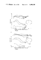
- FIG. 1 is a side elevation view of apparatus of the present invention.
- FIG. 2 is a side elevation, in section and larger scale, of a portion of the apparatus of FIG. 1.
- FIG. 3 is a cross-section view through a water spray zone to show the placement of the baffles, in the apparatus of FIGS. 1 and 2.
- FIG. 4 shows the time-temperature cooling curves measured by placing thermocouples 1 mm, 10 mm and 20 mm below the running surface of the rail and cooling it from 1700° F. in the manner herein described.
- FIG. 5 is a graphical representation of the prior art method of cooling.
- FIG. 6 is a graphical representation of the cooling approach achieved in the present invention.
- FIG. 7 shows graphically the correlation between the cooling stop temperature and yield strength (curve 24) and ultimate tensile strength (curve 25).
- FIG. 8 shows graphically the hardness profiles measured from the centre of the running surface achieved with various cooling stop temperatures.
- FIG. 9 shows graphically the hardness profiles measured from the top corner of the rail head achieved with various cooling stop temperatures.
- FIGS. 1 to 3 Apparatus for in-line accelerated cooling of railroad rails after hot rolling in accordance with the present invention, is illustrated in FIGS. 1 to 3.
- the apparatus comprises a roller type restraining system, comprising a plurality of rollers 9, designed to transport the rail in the longitudinal direction through the spray headers and air zones, whilst keeping the rail at its required position with respect to the sprays, and restraining the rail from distortion due to uneven thermal contraction.
- a roller type restraining system comprising a plurality of rollers 9, designed to transport the rail in the longitudinal direction through the spray headers and air zones, whilst keeping the rail at its required position with respect to the sprays, and restraining the rail from distortion due to uneven thermal contraction.
- a plurality of low pressure water spray headers, 1a and 1b alternate with a plurality of shrouded air zones, 2a and 2b.
- each spray header comprises a plurality of nozzle assemblies 10a, arranged to spray cooling water on the head portion 6 of the rail, and a plurality of nozzle assemblies 10b, arranged to spray cooling water against the central portion of the base bottom 7 of the rail.
- Inclined baffles 3a are provided, to prevent any spray from nozzle assemblies 10a, from reaching rail web 4, and to prevent any drip from the sides of rail head 6, from falling on the upper surfaces of the rail base.
- Vertical lower baffles 3b confine the spray from nozzle assemblies 10b to the central portion of rail base bottom 7, preventing any portion of this spray from reaching base tips 5.
- Air zones 2a and 2b are surrounded by close-coupled shrouds 8a and 8b to minimize fluctuations in air cooling due to any sudden changes in ambient conditions.
- Nozzle assemblies 10a and 10b are connected to a suitable source of pressurized unheated (i.e. "cold” or ambient temperature) water.
- a computer-based control system with associated entry and exit temperature monitoring systems (not shown) is utilized to control the operation of the system.
- the head 6 and base bottom 7 are intermittently cooled by the water sprays in such a manner that heat soak-back during its passage through the alternating air zones is sufficient to keep the near surface region of the rail essentially above the martensite formation temperature.
- the rail head is cooled as quickly as possible until it reaches a predetermined cooling stop temperature. At this point, the water sprays are turned off and the rail is allowed to cool in air.
- FIG. 4 illustrates time-temperature cooling curve measured by implanting thermocouples 1 mm, 10 mm and 20 mm below the running surface of a rail section and cooling it in an experimental apparatus in the manner herein described, and demonstrates the effectiveness of this approach.
- Curves 21, 22 and 23 represent the values at the 1 mm, 10 mm and 20 mm positions, respectively.
- Steps 24 in curve 21, of course, represent the heat soak-back stages between spray headers.
- FIGS. 5 and 6 graphically compare the cooling approach taught in the previously mentioned prior art with that achieved in the present invention.
- the continuous cooling transformation curves shown in FIGS. 5 and 6 are well understood by those skilled in the art of rail steel metallurgy.
- the slope of the cooling curve from the Ae 3 temperature to the transformation start temperature is critical and must be controlled within very tight tolerances in order to avoid the formation of martensite or large volume fractions of bainite while still achieving the desired fine pearlite.
- cooling described by line 10-11 would result in the formation of martensite. Cooling along line 10-12 results in large volume fraction of bainite. Cooling in the region bounded by lines 10-13 and 10-14 results in the desired fine pearlite.
- Cooling at rates slower than described by line 10-14 results in deterioration of rail physical properties due to increasingly coarse pearlite being formed.
- cooling from above the austenite to ferrite transformation temperature anywhere in the region bounded by lines 15-16-20 and 15-19-20 in FIG. 6 achieves the desired fine pearlite.
- the effect of varying the cooling stop temperature is shown in the examples given below.
- the rightmost nose shaped curve to FIG. 6 defines the locus of temperatures and times at which 95% of the austenite to pearlite transformation is complete. Termination of the application of the liquid cooling medium at a time before (i.e. to the left of the rightmost curve of FIG. 6) the rightmost nose shaped curve of FIG. 6 means that forced cooling ceases before the completion of the austenite to pearlite transformation.
- the forced cooling of the rail base bottom is designed to help keep the rail straight within the roller restraining system by approximately balancing thermal contraction and stresses associated with metallurgical transformations top to bottom during forced cooling.
- the hot web is above the stress relieving temperature and, therefore, induced stresses will be released immediately.
- the base tips, 5, are kept as hot as possible during the forced cooling in order to prevent over-cooling these areas which could cause the formation of martensite.
- the close coupled shrouds 8 and 8a around the rail in the air cooling zones help prevent convective heat loss and prevent unpredictable changes in the ambient conditions around the rail. They are designed to help stabilize the characteristics of the time-temperature cooling curve discussed above and illustrated in FIG. 4 during the heat soak-back stages, represented by steps 24 in curve 21 of FIG. 4, between water headers.
- roller type restraining system is designed to transport the rail in a head-up position through the water sprays and air zones. It is designed to compensate for the camber that cannot be corrected by the top and bottom cooling and it keeps the rail in the proper location with respect to the water spray nozzles and baffles within the spray headers.
- the detailed design of the roller restraining system would be obvious to those skilled in the art of mechanical engineering and therefore will not be further described herein.
- the computer-based process control system is designed to monitor the rail head temperature as it enters the first water spray header and to automatically adjust the process to compensate for the temperature variation betweeen rails and within the length of any particular rail in order to achieve the desired constant stop temperature.
- Lengths of standard 136 lb. per yard railroad rails with the chemical composition shown in Table I were force cooled by the method herein disclosed with varying cooling stop temperatures in the range of 850° to 1200° F.
- FIG. 7 shows the correlation achieved between the cooling stop temperature and strength.
- FIGS. 8 and 9 show hardness profiles achieved as functions of distance from the running surfaces of the rail head and cooling stop temperatures.
- a computer based control system appropriate to the process herein disclosed may comprise the following elements:
- a temperature monitoring device such as a pyrometer at the entry end of the cooling apparatus.
- a temperature monitoring device such as a pyrometer at the exit end of the cooling apparatus.
- the programming within the computer contains thermodynamic data, heat transfer information characterizing the cooling equipment and allowable process tolerances. When the temperature of the incoming rail is sensed, the computer automatically activates the correct number of coolant headers required to achieve the desired cooling stop temperature.
- the temperature of the exiting rail is sensed and relayed to the computer which compares it to the desired temperature. If the achieved temperature deviates from the desired temperatures by more than the programmed process tolerance, the computer signals the operating personnel via the cathode ray tube so that appropriate action can be taken (i.e. rail rejected or reapplied to a less critical order). The computer automatically makes adjustments within its programming so that the temperature error is corrected in the next rail processed. (Note: The error could be due to events not detectable by the computing system such as clogged headers and operating personnel would be signalled to take corrective maintenance action).
- each segment of incoming rail is sensed and the number of headers used is varied as the rail progresses through the system to compensate for incoming temperature variation along the length of the rail so that each segment of rail is cooled within tolerance to the desired cooling stop temperature.
Abstract
Description
              TABLE I
______________________________________
             Amount
Element      (Weight Percent)
______________________________________
Carbon       .75
Manganese    .95
Sulphur       .020
Phosphorus    .010
Silicon      .25
Balance      Iron and Incidental
             Impurities
______________________________________
Claims (29)
Priority Applications (1)
| Application Number | Priority Date | Filing Date | Title |
|---|---|---|---|
| US06/405,514 US4486248A (en) | 1982-08-05 | 1982-08-05 | Method for the production of improved railway rails by accelerated cooling in line with the production rolling mill |
Applications Claiming Priority (1)
| Application Number | Priority Date | Filing Date | Title |
|---|---|---|---|
| US06/405,514 US4486248A (en) | 1982-08-05 | 1982-08-05 | Method for the production of improved railway rails by accelerated cooling in line with the production rolling mill |
Related Child Applications (1)
| Application Number | Title | Priority Date | Filing Date |
|---|---|---|---|
| US06/675,772 Division US4611789A (en) | 1982-07-06 | 1984-11-28 | Apparatus for the production of improved railway rails by accelerated cooling in line with the production rolling mill |
Publications (1)
| Publication Number | Publication Date |
|---|---|
| US4486248A true US4486248A (en) | 1984-12-04 |
Family
ID=23604017
Family Applications (1)
| Application Number | Title | Priority Date | Filing Date |
|---|---|---|---|
| US06/405,514 Expired - Lifetime US4486248A (en) | 1982-08-05 | 1982-08-05 | Method for the production of improved railway rails by accelerated cooling in line with the production rolling mill |
Country Status (1)
| Country | Link |
|---|---|
| US (1) | US4486248A (en) |
Cited By (40)
| Publication number | Priority date | Publication date | Assignee | Title |
|---|---|---|---|---|
| US4573666A (en) * | 1983-08-05 | 1986-03-04 | Nippon Kokan Kabushiki Kaisha | Apparatus for quenching butt-welded portion of rail |
| US4575397A (en) * | 1983-10-04 | 1986-03-11 | Krupp Stahl Aktiengesellschaft | Rail having high resistance to wear in its head and high resistance to rupture in its foot |
| US4659398A (en) * | 1985-01-18 | 1987-04-21 | Krupp Stahl Aktiengesellschaft | Method for reducing internal stresses of roller straightened rails |
| US4769092A (en) * | 1986-02-18 | 1988-09-06 | Mtu Motoren-Und-Turbinen-Union Muenchen Gmbh | Variable cooling device for turbo engine wall parts |
| US4810311A (en) * | 1986-07-10 | 1989-03-07 | Centre De Recherches Metallurgiques-Centrum Voor Research In De Metallurgie | Process for manufacturing a high strength rail |
| US4895605A (en) * | 1988-08-19 | 1990-01-23 | Algoma Steel Corporation | Method for the manufacture of hardened railroad rails |
| US4913747A (en) * | 1984-12-24 | 1990-04-03 | Nippon Steel Corporation | Method of and apparatus for heat-treating rails |
| US5000798A (en) * | 1989-11-07 | 1991-03-19 | The Algoma Steel Corporation, Limited | Method for shape control of rail during accelerated cooling |
| US5004510A (en) * | 1989-01-30 | 1991-04-02 | Panzhihua Iron & Steel Co. | Process for manufacturing high strength railroad rails |
| US5191778A (en) * | 1990-06-21 | 1993-03-09 | Nippon Steel Corporation | Process for producing thin-webbed h-beam steel |
| US5259229A (en) * | 1990-06-21 | 1993-11-09 | Nippon Steel Corporation | Apparatus for cooling thin-webbed H-beam steel |
| WO1995000707A1 (en) * | 1993-06-24 | 1995-01-05 | British Steel Plc | Rails |
| EP0685566A1 (en) * | 1993-12-20 | 1995-12-06 | Nippon Steel Corporation | Rail of high abrasion resistance and high tenacity having pearlite metallographic structure and method of manufacturing the same |
| EP0725152A1 (en) * | 1995-02-04 | 1996-08-07 | Sms Schloemann-Siemag Aktiengesellschaft | Method and device for cooling hot-rolled profiles |
| EP0807692A1 (en) * | 1996-05-15 | 1997-11-19 | Sms Schloemann-Siemag Aktiengesellschaft | Method of cooling structural steel beams |
| AU687648B2 (en) * | 1994-11-15 | 1998-02-26 | Nippon Steel Corporation | Perlite rail of high abrasion resistance and method of manufacturing the same |
| AU702091B2 (en) * | 1994-07-19 | 1999-02-11 | Voest-Alpine Schienen Gmbh | Method and apparatus for heat-treating profiled rolling stock |
| US6086305A (en) * | 1999-01-13 | 2000-07-11 | Illinois Tool Works Inc. | Nails having selected heat treatment and hardening |
| US6109851A (en) * | 1999-01-13 | 2000-08-29 | Illinois Tool Works Inc. | Screws having selected heat treatment and hardening |
| US6174389B1 (en) | 1999-08-17 | 2001-01-16 | Caterpillar Inc. | Fixture and method for selectively quenching a predetermined area of a workpiece |
| EP1111074A2 (en) * | 1999-12-23 | 2001-06-27 | SMS Demag AG | Method and device for cooling hot-rolled profiles |
| US6436474B2 (en) | 1999-01-13 | 2002-08-20 | Illinois Tool Works Inc. | Method of chemically coating fasteners having improved penetration and withdrawal resistance |
| WO2003012151A1 (en) * | 2001-08-01 | 2003-02-13 | Sms Meer Gmbh | Method for cooling work pieces especially shape-rolled products from rail steel |
| US6689230B1 (en) * | 1995-02-04 | 2004-02-10 | Sms Schloemann-Siemag Aktiengesellschaft | Method and apparatus for cooling hot-rolled sections |
| ITLI20090004A1 (en) * | 2009-05-21 | 2010-11-22 | Lucchini S P A | RAILWAY RAILWAYS IN MORROLOGY AND COLONIAL PEARLS WITH A HIGH RELATIONSHIP. |
| US20110139320A1 (en) * | 2009-12-14 | 2011-06-16 | Bramfitt Bruce L | Method of making a hypereutectoid, head-hardened steel rail |
| CN102361725A (en) * | 2009-03-27 | 2012-02-22 | 新日本制铁株式会社 | Device and method for cooling welded rail section |
| WO2014078746A1 (en) * | 2012-11-15 | 2014-05-22 | Arcelormittal Investigacion Y Desarrollo S.L. | Method of making high strength steel crane rail |
| US20140182751A1 (en) * | 2012-12-31 | 2014-07-03 | Pangang Group Panzhihua Steel & Vanadium Co., Ltd. | Heat treatment method of turnout track and the turnout track |
| US9573432B2 (en) | 2013-10-01 | 2017-02-21 | Hendrickson Usa, L.L.C. | Leaf spring and method of manufacture thereof having sections with different levels of through hardness |
| EP3095881A4 (en) * | 2014-01-13 | 2017-09-13 | Scientific And Manufacturing Enterprise "Tomsk Electronic Company" Ltd. | Method and device for thermally processing a steel product |
| CN107208216A (en) * | 2015-01-23 | 2017-09-26 | 新日铁住金株式会社 | Rail |
| US20170283895A1 (en) * | 2014-09-22 | 2017-10-05 | Jfe Steel Corporation | Rail manufacturing method and rail manufacturing apparatus |
| US10385415B2 (en) | 2016-04-28 | 2019-08-20 | GM Global Technology Operations LLC | Zinc-coated hot formed high strength steel part with through-thickness gradient microstructure |
| US10604819B2 (en) | 2012-11-15 | 2020-03-31 | Arcelormittal Investigacion Y Desarrollo, S.L. | Method of making high strength steel crane rail |
| US10619223B2 (en) | 2016-04-28 | 2020-04-14 | GM Global Technology Operations LLC | Zinc-coated hot formed steel component with tailored property |
| CN114854963A (en) * | 2022-04-29 | 2022-08-05 | 武汉钢铁有限公司 | Low-residual-stress trough-shaped steel rail and preparation method thereof |
| US11530469B2 (en) | 2019-07-02 | 2022-12-20 | GM Global Technology Operations LLC | Press hardened steel with surface layered homogenous oxide after hot forming |
| US11613789B2 (en) | 2018-05-24 | 2023-03-28 | GM Global Technology Operations LLC | Method for improving both strength and ductility of a press-hardening steel |
| US11612926B2 (en) | 2018-06-19 | 2023-03-28 | GM Global Technology Operations LLC | Low density press-hardening steel having enhanced mechanical properties |
Citations (8)
| Publication number | Priority date | Publication date | Assignee | Title |
|---|---|---|---|---|
| US3266956A (en) * | 1963-11-29 | 1966-08-16 | Union Carbide Corp | Thermal hardening of rails |
| US3497403A (en) * | 1963-10-30 | 1970-02-24 | Abex Corp | Surface hardening of rails |
| US3519497A (en) * | 1965-04-28 | 1970-07-07 | Lorraine Escaut Sa | Method for the thermal treatment of steel rails |
| DE1583418A1 (en) * | 1967-08-08 | 1972-01-05 | Uk Nii Metallow | Device for hardening rails with a water-air mixture |
| CA1024422A (en) * | 1973-05-02 | 1978-01-17 | Robert J. Henry | Method of treating steel rail |
| SU657883A1 (en) * | 1977-03-11 | 1979-04-25 | Украинский научно-исследовательский институт металлов | Rolled stock cooling device |
| CA1058492A (en) * | 1974-08-16 | 1979-07-17 | Fried. Krupp Huttenwerke Ag | Process for heat treatment of steel |
| US4203783A (en) * | 1977-09-19 | 1980-05-20 | Centre De Recherches Metallurgiques | Process for improving the quality of steel sections |
-
1982
- 1982-08-05 US US06/405,514 patent/US4486248A/en not_active Expired - Lifetime
Patent Citations (8)
| Publication number | Priority date | Publication date | Assignee | Title |
|---|---|---|---|---|
| US3497403A (en) * | 1963-10-30 | 1970-02-24 | Abex Corp | Surface hardening of rails |
| US3266956A (en) * | 1963-11-29 | 1966-08-16 | Union Carbide Corp | Thermal hardening of rails |
| US3519497A (en) * | 1965-04-28 | 1970-07-07 | Lorraine Escaut Sa | Method for the thermal treatment of steel rails |
| DE1583418A1 (en) * | 1967-08-08 | 1972-01-05 | Uk Nii Metallow | Device for hardening rails with a water-air mixture |
| CA1024422A (en) * | 1973-05-02 | 1978-01-17 | Robert J. Henry | Method of treating steel rail |
| CA1058492A (en) * | 1974-08-16 | 1979-07-17 | Fried. Krupp Huttenwerke Ag | Process for heat treatment of steel |
| SU657883A1 (en) * | 1977-03-11 | 1979-04-25 | Украинский научно-исследовательский институт металлов | Rolled stock cooling device |
| US4203783A (en) * | 1977-09-19 | 1980-05-20 | Centre De Recherches Metallurgiques | Process for improving the quality of steel sections |
Non-Patent Citations (21)
| Title |
|---|
| "Hardening of Rail Steels by Quenching in Boiling Water", Industrial Heating, Mar. 1981, pp. 8-10. |
| Absalon, B., et al. "Production of Hardened Rails", Third International Meeting on Rails, Budapest 8-12.9.1935 Hungarian Association for Testing Materials, Budapest 1936. |
| Absalon, B., et al. Production of Hardened Rails , Third International Meeting on Rails, Budapest 8 12.9.1935 Hungarian Association for Testing Materials, Budapest 1936. * |
| Babich, A. P., "Strengthening Heat Treatment for Railroad Rails", Metallurgy, No. 12, pp. 29-31, Dec. 1978. |
| Babich, A. P., Strengthening Heat Treatment for Railroad Rails , Metallurgy, No. 12, pp. 29 31, Dec. 1978. * |
| Fegredo, D. M. et al., "The Development of Very Hard and Strong Premium Rails by Controlled Cooling Procedures", Physical Met. Res. Lab. Canada Center for Mineral and Energy Technology, Report MRP/PMRL 81-43J, Jul. 1981. |
| Fegredo, D. M. et al., The Development of Very Hard and Strong Premium Rails by Controlled Cooling Procedures , Physical Met. Res. Lab. Canada Center for Mineral and Energy Technology, Report MRP/PMRL 81 43J, Jul. 1981. * |
| Hardening of Rail Steels by Quenching in Boiling Water , Industrial Heating, Mar. 1981, pp. 8 10. * |
| Heller, W. et al., "High Strength Pearlitic Steel Does Well in Comparative Tests of Alloy Rails," Railway Gazette International, Oct. 1980, pp. 855-857. |
| Heller, W. et al., High Strength Pearlitic Steel Does Well in Comparative Tests of Alloy Rails, Railway Gazette International, Oct. 1980, pp. 855 857. * |
| Hollworth, B. R. et al., "Feasibility Study of On Site Flame Hardening of Rail," ASME Report No. 78-R-T-8, Jan. 5, 1978. |
| Hollworth, B. R. et al., Feasibility Study of On Site Flame Hardening of Rail, ASME Report No. 78 R T 8, Jan. 5, 1978. * |
| Kalousek, J. et al. "Rail Metalling", Track/Train Dynamics, vol. 1, 1978, published by Canadian Pacific Technical and Operations Research. |
| Kalousek, J. et al. Rail Metalling , Track/Train Dynamics, vol. 1, 1978, published by Canadian Pacific Technical and Operations Research. * |
| Lempitski, V. V., "Effects of Method of Tempering on the Properties of, and Stressed State in, Rails Quenched after Heating by High-Frequency Current", Stal May 1969, pp. 499-501. |
| Lempitski, V. V., Effects of Method of Tempering on the Properties of, and Stressed State in, Rails Quenched after Heating by High Frequency Current , Stal May 1969, pp. 499 501. * |
| Pomey, J. et al., Amelioration des rails Revue de Metallurgie, Jan. 1970. * |
| Smith, Y. E. et al. "Alloy Steels for High Strength As-Rolled Rails," Rail Steels-Developments, Processing and Use, ASTM STP 644, D. H. Stone & G. G. Knupp, Eds., American Society for Testing of Materials 1978, pp. 212-232. |
| Smith, Y. E. et al. Alloy Steels for High Strength As Rolled Rails, Rail Steels Developments, Processing and Use, ASTM STP 644, D. H. Stone & G. G. Knupp, Eds., American Society for Testing of Materials 1978, pp. 212 232. * |
| Tamura, Y. et al., "Development of the Heat Treatment of Rails", Nippon Kokan Technical Report Overseas, No. 29 (1980). |
| Tamura, Y. et al., Development of the Heat Treatment of Rails , Nippon Kokan Technical Report Overseas, No. 29 (1980). * |
Cited By (67)
| Publication number | Priority date | Publication date | Assignee | Title |
|---|---|---|---|---|
| US4573666A (en) * | 1983-08-05 | 1986-03-04 | Nippon Kokan Kabushiki Kaisha | Apparatus for quenching butt-welded portion of rail |
| US4575397A (en) * | 1983-10-04 | 1986-03-11 | Krupp Stahl Aktiengesellschaft | Rail having high resistance to wear in its head and high resistance to rupture in its foot |
| US4913747A (en) * | 1984-12-24 | 1990-04-03 | Nippon Steel Corporation | Method of and apparatus for heat-treating rails |
| US4659398A (en) * | 1985-01-18 | 1987-04-21 | Krupp Stahl Aktiengesellschaft | Method for reducing internal stresses of roller straightened rails |
| US4769092A (en) * | 1986-02-18 | 1988-09-06 | Mtu Motoren-Und-Turbinen-Union Muenchen Gmbh | Variable cooling device for turbo engine wall parts |
| US4810311A (en) * | 1986-07-10 | 1989-03-07 | Centre De Recherches Metallurgiques-Centrum Voor Research In De Metallurgie | Process for manufacturing a high strength rail |
| US4895605A (en) * | 1988-08-19 | 1990-01-23 | Algoma Steel Corporation | Method for the manufacture of hardened railroad rails |
| EP0358362A1 (en) * | 1988-08-19 | 1990-03-14 | The Algoma Steel Corporation, Limited | Method for the manufacture of alloy railway rails |
| US5004510A (en) * | 1989-01-30 | 1991-04-02 | Panzhihua Iron & Steel Co. | Process for manufacturing high strength railroad rails |
| US5000798A (en) * | 1989-11-07 | 1991-03-19 | The Algoma Steel Corporation, Limited | Method for shape control of rail during accelerated cooling |
| US5191778A (en) * | 1990-06-21 | 1993-03-09 | Nippon Steel Corporation | Process for producing thin-webbed h-beam steel |
| US5259229A (en) * | 1990-06-21 | 1993-11-09 | Nippon Steel Corporation | Apparatus for cooling thin-webbed H-beam steel |
| WO1995000707A1 (en) * | 1993-06-24 | 1995-01-05 | British Steel Plc | Rails |
| GB2295179A (en) * | 1993-06-24 | 1996-05-22 | British Steel Plc | Rails |
| GB2295179B (en) * | 1993-06-24 | 1996-10-30 | British Steel Plc | Rails |
| AU679537B2 (en) * | 1993-06-24 | 1997-07-03 | British Steel Limited | Rails |
| US5645653A (en) * | 1993-06-24 | 1997-07-08 | British Steel Plc | Rails |
| EP0685566A1 (en) * | 1993-12-20 | 1995-12-06 | Nippon Steel Corporation | Rail of high abrasion resistance and high tenacity having pearlite metallographic structure and method of manufacturing the same |
| EP0685566A4 (en) * | 1993-12-20 | 1996-03-27 | Nippon Steel Corp | Rail of high abrasion resistance and high tenacity having pearlite metallographic structure and method of manufacturing the same. |
| US5658400A (en) * | 1993-12-20 | 1997-08-19 | Nippon Steel Corporation | Rails of pearlitic steel with high wear resistance and toughness and their manufacturing methods |
| AU702091B2 (en) * | 1994-07-19 | 1999-02-11 | Voest-Alpine Schienen Gmbh | Method and apparatus for heat-treating profiled rolling stock |
| AU687648B2 (en) * | 1994-11-15 | 1998-02-26 | Nippon Steel Corporation | Perlite rail of high abrasion resistance and method of manufacturing the same |
| EP0725152A1 (en) * | 1995-02-04 | 1996-08-07 | Sms Schloemann-Siemag Aktiengesellschaft | Method and device for cooling hot-rolled profiles |
| US6689230B1 (en) * | 1995-02-04 | 2004-02-10 | Sms Schloemann-Siemag Aktiengesellschaft | Method and apparatus for cooling hot-rolled sections |
| CN1076757C (en) * | 1995-02-04 | 2001-12-26 | Sms舒路曼-斯玛公司 | Method and device for cooling hot-rolled shaped material |
| EP0807692A1 (en) * | 1996-05-15 | 1997-11-19 | Sms Schloemann-Siemag Aktiengesellschaft | Method of cooling structural steel beams |
| US6086305A (en) * | 1999-01-13 | 2000-07-11 | Illinois Tool Works Inc. | Nails having selected heat treatment and hardening |
| US6109851A (en) * | 1999-01-13 | 2000-08-29 | Illinois Tool Works Inc. | Screws having selected heat treatment and hardening |
| US6273974B1 (en) | 1999-01-13 | 2001-08-14 | Illinois Tool Works Inc. | Selected heat treatment and hardening method for nails |
| US6364972B1 (en) | 1999-01-13 | 2002-04-02 | Illinois Tool Works Inc. | Method for selectively hardening a carbon steel screw |
| US6436474B2 (en) | 1999-01-13 | 2002-08-20 | Illinois Tool Works Inc. | Method of chemically coating fasteners having improved penetration and withdrawal resistance |
| US6174389B1 (en) | 1999-08-17 | 2001-01-16 | Caterpillar Inc. | Fixture and method for selectively quenching a predetermined area of a workpiece |
| EP1111074A3 (en) * | 1999-12-23 | 2004-01-07 | SMS Demag AG | Method and device for cooling hot-rolled profiles |
| EP1111074A2 (en) * | 1999-12-23 | 2001-06-27 | SMS Demag AG | Method and device for cooling hot-rolled profiles |
| WO2003012151A1 (en) * | 2001-08-01 | 2003-02-13 | Sms Meer Gmbh | Method for cooling work pieces especially shape-rolled products from rail steel |
| CN102361725A (en) * | 2009-03-27 | 2012-02-22 | 新日本制铁株式会社 | Device and method for cooling welded rail section |
| CN102361725B (en) * | 2009-03-27 | 2014-01-01 | 新日铁住金株式会社 | Device and method for cooling welded rail section |
| ITLI20090004A1 (en) * | 2009-05-21 | 2010-11-22 | Lucchini S P A | RAILWAY RAILWAYS IN MORROLOGY AND COLONIAL PEARLS WITH A HIGH RELATIONSHIP. |
| US9512501B2 (en) | 2009-12-14 | 2016-12-06 | Arcelormittal Investigacion Y Desarrollo, S.L. | Hypereutectoid-head steel rail |
| RU2579319C2 (en) * | 2009-12-14 | 2016-04-10 | Арселормитталь Инвестигасион И Десаррольо, С.Л. | Production of hypereutectic steel rail with quenched head |
| CN102859010A (en) * | 2009-12-14 | 2013-01-02 | 安赛乐米塔尔研究与发展有限责任公司 | Method of making a hypereutectoid, head-hardened steel rail |
| WO2011081901A1 (en) * | 2009-12-14 | 2011-07-07 | Arcelormittal Investigacion Y Desarrollo, S.L | Method of making a hypereutectoid, head-hardened steel rail |
| US8721807B2 (en) | 2009-12-14 | 2014-05-13 | Arcelormittal Investigacion Y Desarrollo, S.L. | Hypereutectoid, head-hardened steel rail |
| US8241442B2 (en) | 2009-12-14 | 2012-08-14 | Arcelormittal Investigacion Y Desarrollo, S.L. | Method of making a hypereutectoid, head-hardened steel rail |
| US20110139320A1 (en) * | 2009-12-14 | 2011-06-16 | Bramfitt Bruce L | Method of making a hypereutectoid, head-hardened steel rail |
| AU2010337170B2 (en) * | 2009-12-14 | 2014-08-14 | Arcelormittal Investigacion Y Desarrollo, S.L | Method of making a hypereutectoid, head-hardened steel rail |
| CN102859010B (en) * | 2009-12-14 | 2014-10-29 | 安赛乐米塔尔研究与发展有限责任公司 | Method of making a hypereutectoid, head-hardened steel rail |
| WO2014078746A1 (en) * | 2012-11-15 | 2014-05-22 | Arcelormittal Investigacion Y Desarrollo S.L. | Method of making high strength steel crane rail |
| US9476107B2 (en) | 2012-11-15 | 2016-10-25 | Arcelormittal | Method of making high strength steel crane rail |
| RU2683403C2 (en) * | 2012-11-15 | 2019-03-28 | Арселормитталь Инвестигасьон И Десарролло С.Л. | Method of producing high-strengthening steel valve rails |
| US10604819B2 (en) | 2012-11-15 | 2020-03-31 | Arcelormittal Investigacion Y Desarrollo, S.L. | Method of making high strength steel crane rail |
| US20140182751A1 (en) * | 2012-12-31 | 2014-07-03 | Pangang Group Panzhihua Steel & Vanadium Co., Ltd. | Heat treatment method of turnout track and the turnout track |
| US9765414B2 (en) * | 2012-12-31 | 2017-09-19 | Pangang Group Panzhihua Iron & Steel Research Institute Co., Ltd. | Heat treatment method of turnout track and the turnout track |
| US9573432B2 (en) | 2013-10-01 | 2017-02-21 | Hendrickson Usa, L.L.C. | Leaf spring and method of manufacture thereof having sections with different levels of through hardness |
| US9890440B2 (en) | 2013-10-01 | 2018-02-13 | Hendrickson Usa, L.L.C. | Leaf spring and method of manufacture thereof having sections with different levels of through hardness |
| EP3095881A4 (en) * | 2014-01-13 | 2017-09-13 | Scientific And Manufacturing Enterprise "Tomsk Electronic Company" Ltd. | Method and device for thermally processing a steel product |
| US20170283895A1 (en) * | 2014-09-22 | 2017-10-05 | Jfe Steel Corporation | Rail manufacturing method and rail manufacturing apparatus |
| CN107208216A (en) * | 2015-01-23 | 2017-09-26 | 新日铁住金株式会社 | Rail |
| EP3249070A4 (en) * | 2015-01-23 | 2018-06-27 | Nippon Steel & Sumitomo Metal Corporation | Rail |
| US10385415B2 (en) | 2016-04-28 | 2019-08-20 | GM Global Technology Operations LLC | Zinc-coated hot formed high strength steel part with through-thickness gradient microstructure |
| US10619223B2 (en) | 2016-04-28 | 2020-04-14 | GM Global Technology Operations LLC | Zinc-coated hot formed steel component with tailored property |
| US11613789B2 (en) | 2018-05-24 | 2023-03-28 | GM Global Technology Operations LLC | Method for improving both strength and ductility of a press-hardening steel |
| US11612926B2 (en) | 2018-06-19 | 2023-03-28 | GM Global Technology Operations LLC | Low density press-hardening steel having enhanced mechanical properties |
| US11951522B2 (en) | 2018-06-19 | 2024-04-09 | GM Global Technology Operations LLC | Low density press-hardening steel having enhanced mechanical properties |
| US11530469B2 (en) | 2019-07-02 | 2022-12-20 | GM Global Technology Operations LLC | Press hardened steel with surface layered homogenous oxide after hot forming |
| CN114854963A (en) * | 2022-04-29 | 2022-08-05 | 武汉钢铁有限公司 | Low-residual-stress trough-shaped steel rail and preparation method thereof |
| CN114854963B (en) * | 2022-04-29 | 2023-09-05 | 武汉钢铁有限公司 | Groove-type steel rail with low residual stress and preparation method thereof |
Similar Documents
| Publication | Publication Date | Title |
|---|---|---|
| US4486248A (en) | Method for the production of improved railway rails by accelerated cooling in line with the production rolling mill | |
| US4611789A (en) | Apparatus for the production of improved railway rails by accelerated cooling in line with the production rolling mill | |
| US4913747A (en) | Method of and apparatus for heat-treating rails | |
| US10125405B2 (en) | Method and system for thermal treatments of rails | |
| US4082577A (en) | Process for the heat treatment of steel | |
| EP1412543B1 (en) | Method for cooling work pieces especially shape-rolled products from rail steel | |
| US4933024A (en) | Method for manufacturing a high strength rail with good toughness | |
| RU2162486C2 (en) | Method for heat treatment of steel rail | |
| US20220112571A1 (en) | Method of producing steel material, apparatus that cools steel material, and steel material | |
| JP6658895B2 (en) | Rail cooling device and manufacturing method | |
| US5004510A (en) | Process for manufacturing high strength railroad rails | |
| US4668308A (en) | Method and apparatus for manufacturing rails | |
| JP7070697B2 (en) | Rails and their manufacturing methods | |
| CA2154090C (en) | Method and apparatus for heat-treating profiled rolling stock | |
| JP2651677B2 (en) | Rail heat treatment method | |
| US5000798A (en) | Method for shape control of rail during accelerated cooling | |
| GB2118579A (en) | Heat treatment of rails | |
| JPS6160827A (en) | Shape straightening and cooling method of high temperature rail | |
| JP2773867B2 (en) | Hot rail cooling | |
| JPH03166318A (en) | Method for heat-treating rail | |
| GB1563919A (en) | Controlled cooling of hot-rolled steel products | |
| JPS5923818A (en) | Method and device for heat treatment of shape steel | |
| JPS62192535A (en) | Cooling method for steel pipe |
Legal Events
| Date | Code | Title | Description |
|---|---|---|---|
| AS | Assignment |
Owner name: ALGOMA STEEL CORPORATION LIMITED,THE, SAULT STE. M Free format text: ASSIGNMENT OF ASSIGNORS INTEREST.;ASSIGNORS:ACKERT, ROBERT J.;WITTY, ROBERT W.;CROZIER, PETER A.;REEL/FRAME:004031/0016 Effective date: 19820709 |
|
| STCF | Information on status: patent grant |
Free format text: PATENTED CASE |
|
| CC | Certificate of correction | ||
| AS | Assignment |
Owner name: CANNELTON INDUSTRIES, INC., CHARLESTON, WEST VA A Free format text: ASSIGNMENT OF ASSIGNORS INTEREST.;ASSIGNOR:ALGOMA STEEL CORPORATION LIMITED, THE;REEL/FRAME:004700/0982 Effective date: 19870401 |
|
| FEPP | Fee payment procedure |
Free format text: PAYOR NUMBER ASSIGNED (ORIGINAL EVENT CODE: ASPN); ENTITY STATUS OF PATENT OWNER: LARGE ENTITY |
|
| FPAY | Fee payment |
Year of fee payment: 4 |
|
| SULP | Surcharge for late payment | ||
| FEPP | Fee payment procedure |
Free format text: PAYOR NUMBER ASSIGNED (ORIGINAL EVENT CODE: ASPN); ENTITY STATUS OF PATENT OWNER: LARGE ENTITY Free format text: PAYER NUMBER DE-ASSIGNED (ORIGINAL EVENT CODE: RMPN); ENTITY STATUS OF PATENT OWNER: LARGE ENTITY |
|
| FPAY | Fee payment |
Year of fee payment: 8 |
|
| AS | Assignment |
Owner name: ALGOMA STEEL INC., CANADA Free format text: ASSIGNMENT OF ASSIGNORS INTEREST.;ASSIGNOR:ALGOMA STEEL CORPORATION, LIMITED, THE A CORP. OF ONTARIO, CANADA;REEL/FRAME:006182/0338 Effective date: 19920623 |
|
| AS | Assignment |
Owner name: MONTREAL TRUST COMPANY OF CANADA, A CANADIAN TRUST Free format text: SECURITY AGREEMENT;ASSIGNOR:ALGOMA STEEL INC., A CORP. OF ONTARIO, CANADA;REEL/FRAME:007588/0905 Effective date: 19950804 |
|
| FPAY | Fee payment |
Year of fee payment: 12 |
|
| AS | Assignment |
Owner name: BANK OF AMERICA CANADA, CANADA Free format text: SECURITY INTEREST;ASSIGNOR:ALGOMA STEEL, INC.;REEL/FRAME:011812/0022 Effective date: 20010516 |
|
| AS | Assignment |
Owner name: BANK OF AMERICA, NATIONAL ASSOCIATION, CANADA Free format text: SECURITY INTEREST;ASSIGNOR:ALGOMA STEEL INC.;REEL/FRAME:012683/0071 Effective date: 20020129 |
|
| AS | Assignment |
Owner name: BANK OF AMERICA N.A., CALIFORNIA Free format text: ASSIGNMENT OF ASSIGNORS INTEREST;ASSIGNOR:ALGOMA STEEL INC.;REEL/FRAME:015302/0914 Effective date: 20030827 Owner name: BANK OF AMERICA N.A., CANADA Free format text: RELEASE,DISCHARGE AND UNDERTAKING;ASSIGNOR:ALGOMA STEEL INC.;REEL/FRAME:014515/0268 Effective date: 20030903 |